1. Introduction
A reflex reflector is an optical device that allows light to be reflected in a direction that is parallel to that of the source [
1,
2,
3]. The corner cube array is the typically used structure and such an array can be built up through pin grouping to generate the expected retro-reflected light [
4,
5,
6]. Reflex reflectors on cars or signage can increase visibility in the dark for safety [
7,
8], so they have been applied extensively in vehicle applications [
9]. Due to their high tolerance to the direction of incident waves [
10,
11,
12] retroreflectors have been used extensively in many applications instead of plane mirrors [
13]. For instance, regular reflex reflectors [
14,
15,
16], as shown in
Figure 1a, can diverge the reflected energy into multiple light beams with equal emitting angle intervals [
17,
18,
19], and these are currently the most commonly used retro-reflecting devices for vehicles [
20,
21]. In contrast to regular reflex reflectors, SuperPin reflex reflectors not only reflect light beams but also concentrate them to amplify the light intensity of signals for observers, as shown in
Figure 1b [
22]. Owing to the highly effective retro-reflection ability, SuperPin retro-reflectors have been replacing regular retroreflectors in vehicle application markets [
17,
21,
23].
According to regulations of the US Society of Automotive Engineers (SAE) and EU Economic Commission for Europe (ECE), reflex reflectors for vehicles need to return light to an observer located at 0.2 degrees (SAE regulations) and 0.33 degrees (ECE regulations) above the light source [
23], respectively. Therefore, corner cube arrays composed of pins need to be designed and produced with different specification for the requirements of ECE and SAE reflex reflectors, respectively. In this paper, a new reflex reflector structure called SuperPin Plus is proposed for fitting both the ECE and SAE regulations, shown in
Figure 1c. SuperPin Plus’s principle is based on the structure of SuperPin [
24], which was developed by the difference in the value of dihedral angle.
The reflex reflector can switch its function from ECE to SAE or SAE to ECE just by rotating pins group 45° in structure, so one type of pin is enough to handle the production of ECE and SAE reflex reflectors. Flat SuperPin Plus reflex reflectors and curved SuperPin Plus reflex reflectors with the new corner cube structure are proposed and demonstrated to meet the ECE/SAE dual function requirements through experiments. By using genetic algorithms for optimization, we use the angles and the positions of the pins serving as the building elements of corner cube reflectors as the parameters to enhance the performance of the SuperPin Plus curved reflex reflector. Compared with conventional regular retro-reflectors, it is found that not only can 41% higher retro-reflection efficiency be achieved with the ECE SuperPin Plus flat reflex reflector, but the SuperPin Plus can also act as a SAE reflex reflector. It is shown that a 32% larger working area can be achieved if double pin groups are used to construct corner cubes instead of the single pin arrangement in a curved SuperPin Plus reflex reflector.
Accoding to the standards of SAE and ECE, the coefficient of luminous intensity
RI should be higher than the threshold values within the 20° angle of light incidence [
23,
24,
25]. The vehicle signage performance
RI is evaluated by the ratio of the strength of the reflected light
ϕRLI (retro-reflected light intensity) to the amount of light that falls on the retro-reflector
ϕILI (incident light illuminance), as shown in
Figure 1. The minimum coefficients of luminous intensity
RI requiement for EU ECE or US SAE standards are shown in
Table 1.
RA is the measure of retro-reflection efficiency, defined as the ratio of the flux of incident light
ϕ1 to the total flux of the reflected cone
ϕ2 [
18,
23]. Consequently, vehicle signage would be observed to be brighter as its
RI value increases [
23]. It is usual for reflex reflectors to have a curved shape; for example, to fit the corner of a vehicle [
1,
2,
3,
4,
5,
18]. Corner cube structures are thus distorted to complete the curve, so that their active working area and reflection efficiency are affected, thus leading to a retro-reflector that is against regulations [
19,
25].
2. Principles
A corner cube retro-reflector (CCR) is based on groups of three perpendicular planes, as shown in
Figure 2. Conventionally, the dihedral angle between any pair of reflecting faces is made to be 90° [
1], so that the reflected beam is exactly contradictory directional to the incident beam [
13]. If the angles differ from 90° by a specific amount, the reflected beam will be converged or diverged in multiple beams to achieve the required application [
1]. We can move the three retro-reflected rays on the top into one direction and the other three into another direction by using the different angles between each pair of facets. In this way, the optical performance of a corner cube can be improved as the retro-reflected energy in a given direction is tripled; this is called superpin technology [
24]. The superpin technology is characterized by the unique structure of corner cubes to concentrate the retroreflected light into two zones insteads of six zones, shown in
Figure 2c. The SuperPin Plus structure was developed based on the superpin technology with the same specification of the pins. The experiment beam pattern retro-reflected from the superpin plus corner is shown in the next section.
Through an array of pins, corner cube retro-reflectors can be produced, as shown in
Figure 2. The direction of the reflected rays after the reflections are given by Chandler’s formula:
where
is the final direction;
is the original direction; α, β, and γ are the small angles, by which the angles between the three mirrors exceed right angles; and
,
, and
are normal to the three mirrors taken in the order in a right-hand sense. The unit normals to the faces can be computed as follows, as shown in
Figure 3. Let the normals to the faces without dihedral-angle offsets be the unit vectors
, , and
along the three coordinates x, y, and z, respectively. If the angle between the zx plane, and the zy plane is α = (π/2) + δ
1, the xz plane and the xy plane is β = (π/2) + δ
2, the yz plane and the yx plane is γ = (π/2) + δ
3, shown in
Figure 3b; this can be expressed by Equations (2)–(4),
The retro-reflected beam spread angle at normal beam incidence when all dihedral angles are offset by the same amount is given by the formulas (5)–(7),
where δ is the dihedral angles of corner cubes and ε is the angle between the incident ray and the reflected rays, thus there will be several retro-reflected rays generated, once one ray is incident on CCR. The direction of the incident beam is determined by θ′ and ϕ′ in the primed coordinate system. By adjusting the angles between each pair of facets, we can set the six retro-reflected rays with equal angle intervals or let them propagate in almost contradictory directions, such as the simulation results performed by regular, SuperPin, and SuperPin Plus retro-reflectors, as shown in
Figure 4a–c.
After analyzing the values of the angles α, β, and γ, we concluded the influence of incident angle on the value and position of the reflected beams. In case 1: α = β = γ, the reflected beam is divided into six small beams that are symmetrical with each other in a circle, known as regular structure, shown in
Figure 4a. In case 2: α = β < γ, the reflected beams converged into two symmetric groups on the top and bottom (three beams on the top and three beams on the bottom), known as the SuperPin structure, shown in
Figure 4b. In case 3: α = β > γ, the reflected beams converged to four beams at the top and bottom positions (two beams on the top and two beams on the bottom) and two beams at the left and right locations (one beam on the left and one beam on the right), known as the SuperPin Plus structure, shown in
Figure 4c. The SuperPin Plus structure, which is accomplished by our proposal, will reduce manufacturing costs as well as be more advantageous as it can be used in both the European and American markets.
When the dihedral angles δ
1 = 0.12°; (α = 90.12°); δ
2 = 0.12°; (β = 90.12°); and δ
3 = 0.01° (γ = 90.01°), the CCR is called the SuperPin Plus type, where the reflected beam angle can be calculated as ε
1 = ε
2 = 0.33°, ε
3 = 0.2°, and the luminous intensity
RI meets EU ECE and US SAE regulation requirements. In
Figure 5, the simulation results through the TracePro software (Lambda Research Corporation of Littleton, Massachusetts, USA) can verify the above ε and δ relation formulas. In
Figure 5b,d, the retro-reflected light can reach up to 0.2°, and up to 0.33° through the CCR shown in
Figure 5a and the 45° rotated CCR, shown in
Figure 5c respectively. Therefore, the SuperPin Plus design can simultaneously meet SAE and ECE standards by using pins with the same specifications. For the requirements of the SAE standard, the direction of CCR is determined by the original orientation, shown in
Figure 5a. For ECE standards, we only need to rotate the CCR at a 45-degree angle, as shown in
Figure 5c. The results are detailed in
Figure 5b,d.
3. Experimental Setups and Analysis
In order to demonstrate the performance of the SuperPin Plus CCR, the pin element for corner cubes with 2.75 mm cross sectional size and dihedral angles δ1 = 0.12°; (α = 90.12°); δ2 = 0.12°; (β = 90.12°); and δ3 = 0.01° (γ = 90.01°) are made by CNC process and bundled as a flat array testing CCR sample, as shown in
Figure 6. In optical testing processes, the sample is tested for ECE regulation verification first, and then it is rotated 45° for SAE regulation measurement. For comparison, one flat SAE regular CCR and one flat ECE regular CCR are also put in an optical setup to test. The optical setup for reflex reflector regulation testing is established, as shown in
Figure 7, with a 633 nm diode laser operated with a 5 mW output acting as the light source, and the distance between the laser and the curved reflex reflector set to 30.5 m to measure the reflected light spot. Based on the laser spectrum specification, its coherence length is calculated to be about 0.5 mm, which is less than the corner cube dimension of 2.75 mm in the experiments. Therefore, the retro-reflected output spots were spatially incoherent, and the laser can be considered as an incoherent light source for the following retro-reflector testing experiments.
The laser light had an incident angle of 0° with respect to the car driving direction, as it shone on the tested CCR with a spot area of 520 mm2. As a result, several retro-reflected light spots can be found on the black screen located 30.5 m away from the test sample. A Minolta T10 illuminance meter was used to measure the illuminance of the sample and of the retro-reflected light spot in order to get the incident light illuminance (in lux) and the retro-reflected light intensity (in candela). The coefficient of luminous intensity RI and retro-reflection efficiency RA of the test sample can be obtained through calculation of the measured data to ensure that the tested CCRs can pass US SAE regulations and EU ECE regulations.
The testing output light patterns of the ECE SuperPin Plus CCR, the SAE SuperPin Plus CCR, the flat ECE regular CCR, and the flat SAE regular CCR are shown in
Figure 8a–d, respectively. Based on the measured data in
Figure 8, comparing the light reflection performance of R
I between the regular CCRs and the SuperPin Plus CCR, the results show that the light reflection performance of the new design is higher than that of the regular ones. In detail, the
RI values of the flat SuperPin Plus sample under ECE working conditions at 0°, 10°U, 10°D, 20°L, and 20°R are 20,002 millicandela (mcd)/lux, 10,214 mcd/lux, 7863 mcd/lux, 7318 mcd/lux, and 8871 lux/mcd, respectively, shown in
Figure 8e The
RI values of the flat SuperPin Plus sample under the SAE working mode at 0°, 10°U, 10°D, 20°L, and 20°R are 12,318 mcd/lux, 6227 mcd/lux, 4442 mcd/lux, 4586 mcd/lux, and 4904 lux/mcd, respectively, shown in
Figure 8f. The measured coefficients of luminous intensity
RI of the SuperPin Plus CCR are all higher than the regulation requirement of ECE and SAE, shown in
Table 1. Based on the data shown in
Figure 8, we can conclude that the retro-reflection efficiency of the SuperPin Plus CCR is 41% higher comparing to the ECE regular one, and can have the same regulation level as the SAE regular one, respectively.
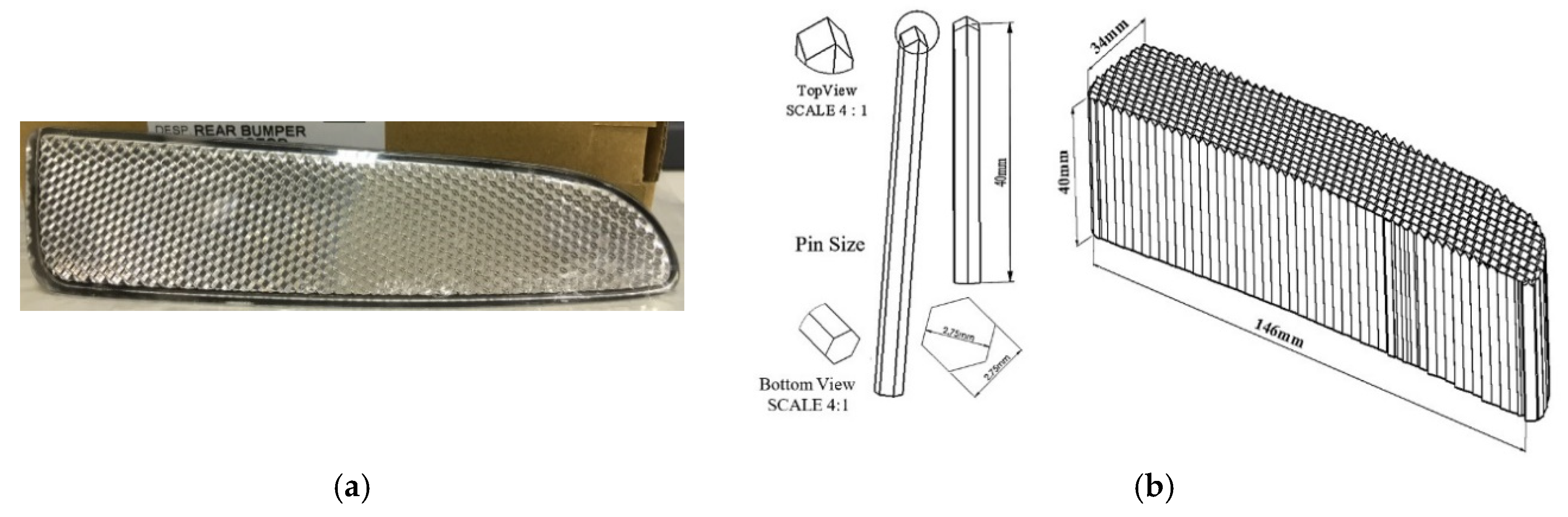
In order to extend the ECE/SAE dual functional advantage from a flat SuperPin Plus CCR to a curved SuperPin Plus CCR, the SuperPin Plus pin elements are connected side by side with their tips touching the curved plane of a commercial curved CCR, serving as the initial design of the curved SuperPin Plus CCR. The commercial curved regular CCR made of PMMA (polymethyl methacrylate) shown in
Figure 9 provided by OWL LIGHT AUTOMOTIVE MFG. CORP (Lukang, Chunghua, Taiwan) is used as the reference to design a SuperPin Plus curved retro-reflector. The commercial curved regular CCR and the initial SuperPin Plus curved CCR design are shown in
Figure 9a,b, respectively. The cross section working surface of the design is 146 mm × 34 mm. Through TracePro software simulation, the anterior, central, and posterior regions of the ECE (SAE) SuperPin Plus curved CCR result in their retro-reflected light intensity distributions for an incident beam in the driving direction, as shown in
Figure 10. The locations of the probing regions and the car’s driving direction of the CCRs are presented in
Figure 11. As the simulation results are shown in
Figure 10, the anterior and the central regions areas can reflect light up to 0.2° and up to 0.33°, but the posterior area can not. Therefore, we conclude that it is difficult for the posterior area to meet ECE or SAE regulation requirements.
In order to remedy the ineffective posterior working area of the commercial design, two groups of pins were connected as the double pins group to compose the SuperPin Plus curved CCR, as shown in
Figure 12. Fifteen pieces of double-pin groups were arranged in parallel to the car driving direction to form the primary curved CCR; one pin group touches the curve reference surface, and the other one is free to translate in the car driving direction. The height difference between the neighboring pins in a group of double pins and the double pin group are named d
i and D
i, respectively.
The object function f defined by Equation (8) was determined in the optimization process. The optimization process encompassed three fragments.
Object function: The equation that describes the value of the object function of the optimization program established by genetic algorithms is as follows:
where
wi is the weight parameter of the object function,
mj is the value of the measured target, which is determined by the intensity sensor through each optimal loop when running the program, and
tj is the optimization target defined with a value corresponding to the retro-reflective light intensity on the retroreflector plane.
Luminous intensity function: In order to improve the primary curved CCR further, the add-on ray tracing simulation tool OptisWork (Optis SAS, La Farlede, France), embedded in SolidWorks mechanical design software, was used to search for suitable variable parameters to get an optimized curved CCR, using d
i to elevate its performance and D
i to fit the reference curve for the outlook of curved CCR smoothly. The constraint of each variable parameter is determined by the curvature of the curved CCR surface. The lighting performances, such as intensity distributions, illumination uniformity, and optical efficiencies of curved CCR, can be accomplished to meet targets by using optimization. In the study, the luminous intensity function serves as the object function, and the value R
I at the upper 0.33° is targeted to be maximum in the solution searching process. We search for an approximation of the luminous intensity (
RI) I(φ, a, b, c) as the object function, which is at the polar angle Φ in Equation (9), where K is the number of functions.
In order to set the target value of the optimization, the simulation experiment with a flat regulated CCR was exercised to find the reflected light power as the reference by a 1000 lumen incident beam. The resulting power was 850 lm and this was used as the target for the subsequent searching of the optimized curved CCR. By running the scheme in optimization steps, manually limited to 600 searching steps to quickly find a better solution, the best results were determined in step 18 (SAE curve) and step 79 (ECE curve). The final intensity sensor values were shown to be 742.51 lm (SAE curve) and 802.1 lm (ECE curve), which were also the output powers reflected by the optimized curved CCR.
In the initial optimization process, the mathematical equation for the intensity distribution of reflected light entered into the program is expressed in the measurement value of the intensity sensor. The luminous intensity
RI is defined by I (φ, a, b, c) at the polar angle of φ, shown in Equation (9). The target of the optimization process was defined as a value corresponding to the retro-reflective light intensity on the retro-reflector plane. During the optimization, to have the curved CCR meet the requirement of the ECE (0.33°) and SAE 0.2°) standard and maximum reflection efficiency, the values of δ and d
i were found through the workflows shown in
Figure 13 and
Figure 14, respectively.
As the optimization is terminated by the program, the optimized curved CCR with the same curve as the commercial one was obtained. After the optimization process, the optimized curved CCR was analyzed for comparison with the commercial reflector by simulations. The distance from the light source to the curved CCR is set as 30.5 m, and the diameter of the laser beam is 25 mm. The curved CCR is kept with its car driving direction at 0°, 10° (up, down) vertically, and 20° (left, right) horizontally with the incident light, respectively, to perform the optical tests of SAE and ECE regulations. The resulting intensity distributions by 0° incident light to the anterior, central, and posterior regions sequentially are shown in
Figure 15 and
Figure 16. The results showed that the optimized curved CCR could contribute much higher sufficient light intensity than that of the commercial design (no effective retro-reflection at 0.2° (SAE), 0.33° (ECE) up), as shown in
Figure 15c for regular SAE curved CCR and shown in
Figure 16c for regular ECE curved CCR. Additionally, it was demonstrated that
RI and
RA are also increased significantly in all regions, and a larger retro-reflection working area is accomplished through the optimal design.
The optimization results shown in
Figure 15 and
Figure 16, that demonstrate the intensity distributions on the posterior regions were improved. We compared with the results shown in
Figure 10 the posterior regions have reflected beams on top, as shown in
Figure 15c and
Figure 16c. In order to demonstrate that the optimized SuperPin Plus curved CCR can meet SAE and ECE requirements and perform better than the commercial samples, we prototyped and tested the SuperPin Plus in practical experiments, as shown in
Figure 17. The retro-reflected outputs on the screen by the commercial regular curved CCRs shown in
Figure 18a–d and the optimized curved CCR were presented in
Figure 19a–d, respectively, resulted in
RI values for rotational angles of 0°, 10°U, 10°D, 20°L, and 20°R, as shown in
Figure 20 and
Figure 21. At the posterior area of the commercial curved CCR sample, it can be found that the
RI values were 0 mcd/lux. However, the
RI of the optimal curved SuperPin Plus CCR sample was much improved.
4. Conclusions and Discussions
One of the most crucial advantages of this research on the SuperPin Plus curved reflex-reflector can decrease the production cost of the reflex reflector severely, as the design can reflect one incident beam as two groups of beams to 0.20° and 0.33°, respectively, as shown in
Figure 5. This allows the SuperPin Plus to meet both SAE and ECE standards while using the same type of pins with the same dimension and shape. Function switching between SAE and ECE standards only needs CCRs to rotate 45°. The new optimal CCR design is shown to surpass the performance of the typical one. By using double-pin groups to build the SuperPin Plus curved CCR, reflection efficiency can be improved. Through using OptisWork software to find out the optimized SuperPin Plus curved CCR,
RI can be increased further; however, this does sacrifice the reflection efficiency,
RA. Using an efficient working area ratio, reflection efficiency
RA, and coefficient of luminous intensity
RI as the evaluation indices of curved CCR to compare a commercial regular curved CCR with the proposed new design.
It can be inferred that the optimized SuperPin Plus curved CCR redistributes the reflected light beam energy of the initial SuperPin Plus curved CCR design, which takes more energy from other retro-reflected beams into the up 0.2° (SAE) or up 0.33° (ECE). After computer simulations and optical experiments, we demonstrated that the proposed SuperPin Plus curved CCR is not only above the SAE and ECE standard but also has a 32% larger working area and much better reflection efficiency than the commercial CCR, whose posterior region is not effective at all.
Based on the data in
Figure 20 and
Figure 21, it can be computed that the ratio of averaged
RI of the optimized SuperPin Plus SAE curved CCR to that of the commercial SAE curved CCR is (10,172/7,380, 0°), (8,489/5,972, 10°U), (7,826/5,268, 10°D), (7,479/5,322, 20°L), and (6,678/4,427, 20°D), which means 27.4% (0°), 29.6% (10°U), 32.7% (10°D), 28.8% (20°L), and 33.7% (20°R) higher retro-reflection efficiency can be accomplished by the proposed SuperPin Plus SAE curved CCR. In addition, the ratio of averaged
RI of the optimized SuperPin Plus ECE curved CCR to that of the commercial ECE curved CCR is (13,446/8,145, 0°), (11,306/6,203, 10°U), (10,194/5,888, 10°D), (9,451/5,457, 20°L), and (9,139/5,093, 20°D), which means 39.4% (0°), 45.1% (10°U), 42.2% (10°D), 42.3% (20°L), and 44.28% (20°R) higher retro-reflection efficiency can be accomplished by the proposed SuperPin Plus ECE curved CCR.
In conclusion, we proposed a reflex reflector with a new corner cube structure. Compared with conventional ECE regular retro-reflectors, we found that not only can a 41% higher retro-reflection efficiency be achieved with the ECE SuperPin Plus flat reflex reflector, but also that the SuperPin Plus can act as a reflex reflector for the SAE standard. By using genetic algorithms for optimization, the angles and the positions of the pins considered as the building parameters of corner cube reflectors can influence the performance of a curved reflex reflector. It is demonstrated that 32% larger working area can be increased if double pin groups are used to construct corner cubes instead of the single pin arrangement in a curved SuperPin Plus reflex reflector. The yield rate of the mold production of the optimized design is less than the commercialized design as, through the pin composition method, the precision of the pin height control is even more necessary. In order to overcome the technical problems, we are conducting a study into molding by ultra-high precision casting. Moreover, a product that is accomplished by our proposed reflex reflector will reduce manufacturing costs so as to be more advantageous for both the European and American markets.

 ,
, 


