Opto-Mechanical Photonic Crystal Cavities for Sensing Application


Abstract
:1. Introduction
2. Photonic Crystal Cavities for Opto-Mechanical Interaction
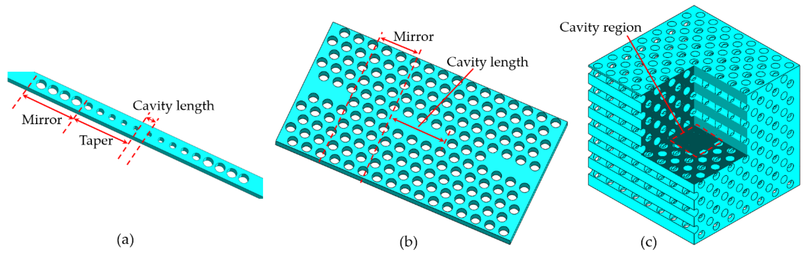
2.1. Photonic Crystal Cavities
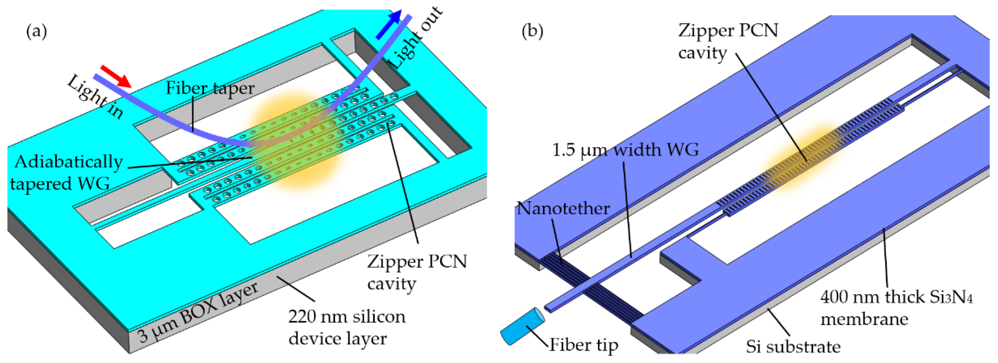
2.2. Experimental Opto-Mechanical PhC Cavities
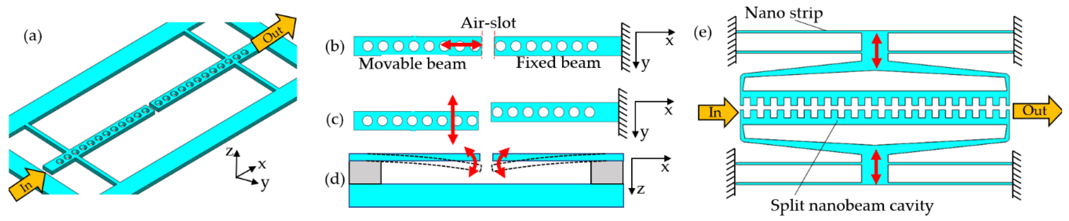
2.2.1. One-Dimensional Photonic Crystal Nanobeam in Opto-Mechanical System
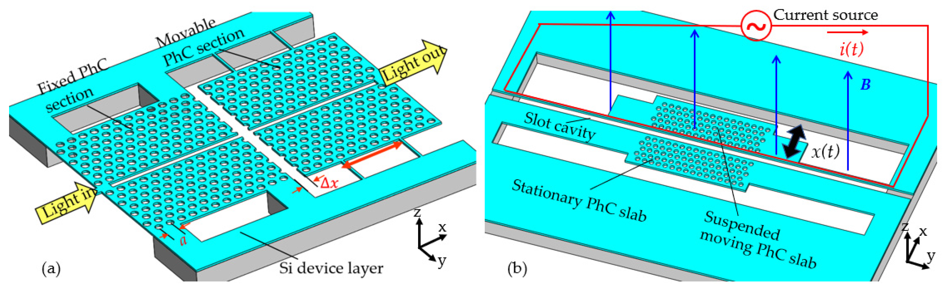
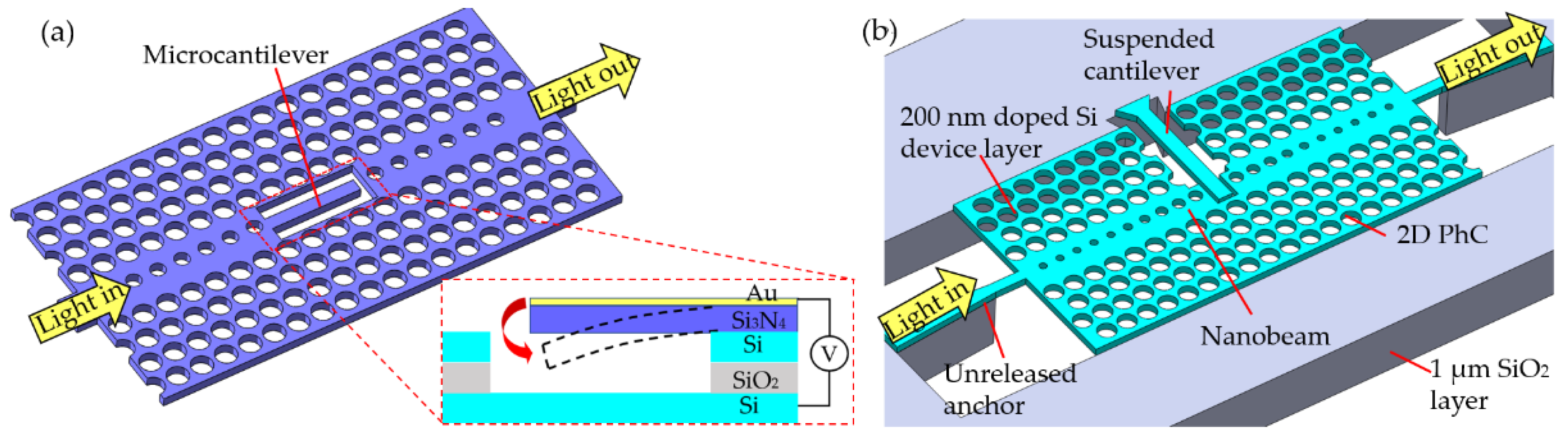
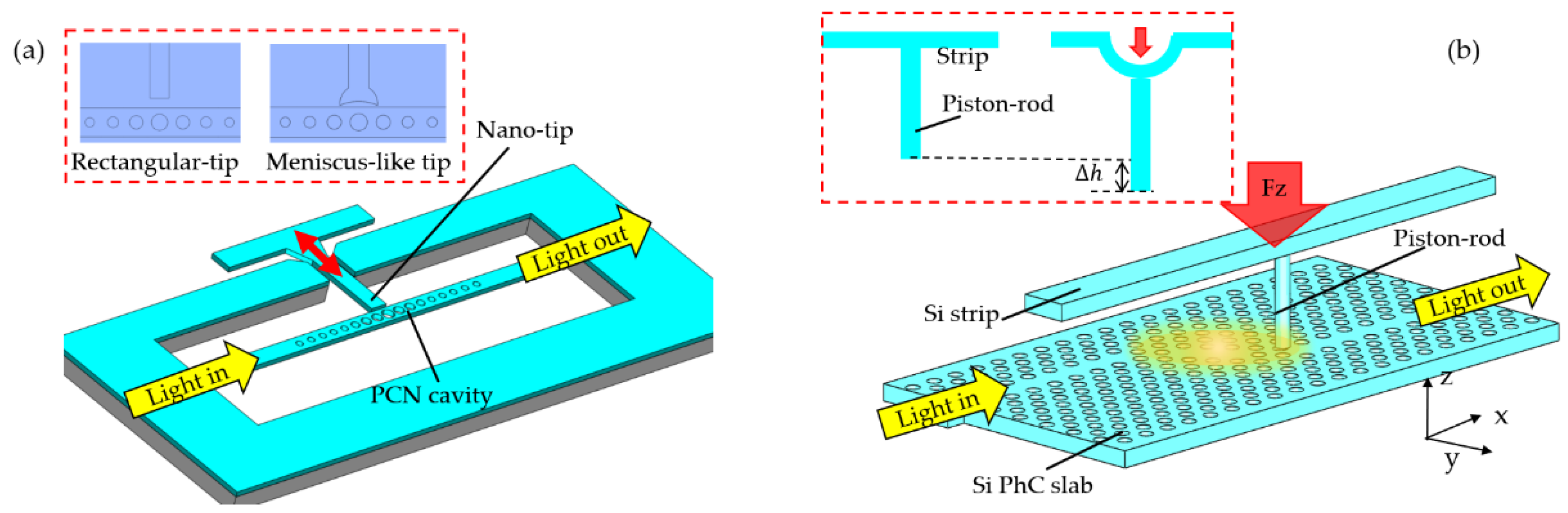
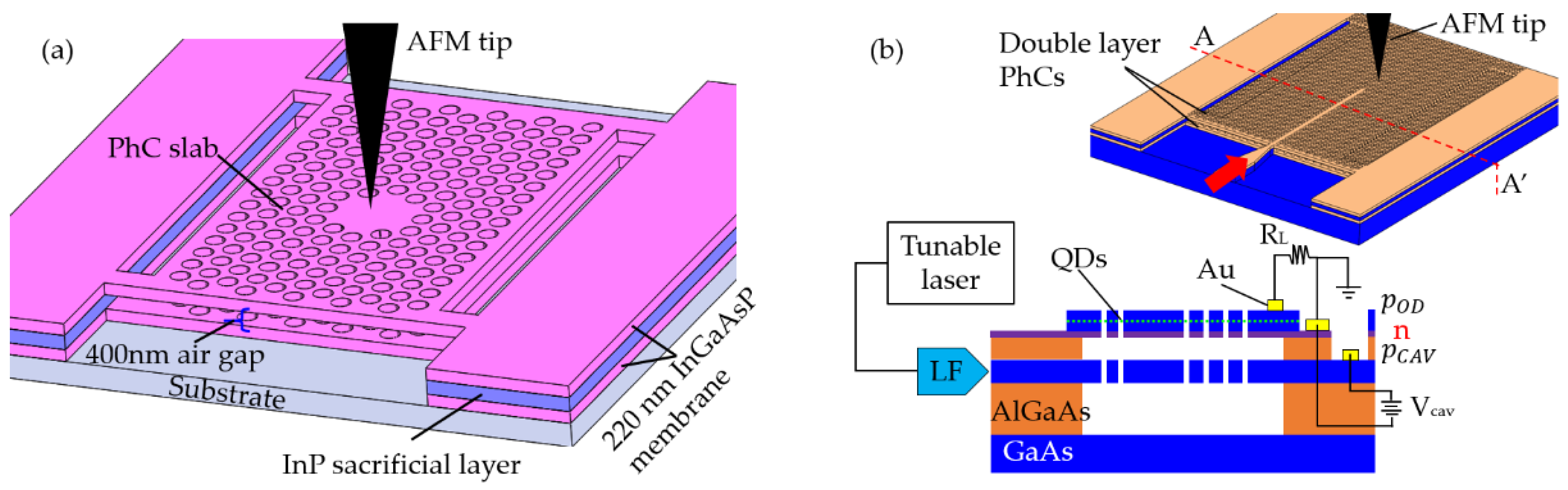
2.2.2. Two-Dimensional Photonic Crystal Cavity in Opto-Mechanical System
2.3. Discussion
3. Mechanically Tunable PhC Cavity Sensors
3.1. Sensing Mechanisms of Mechanically Tunable PhC Cavities Sensors
3.2. Sensing Applications of Mechanically Tunable PhC Cavities
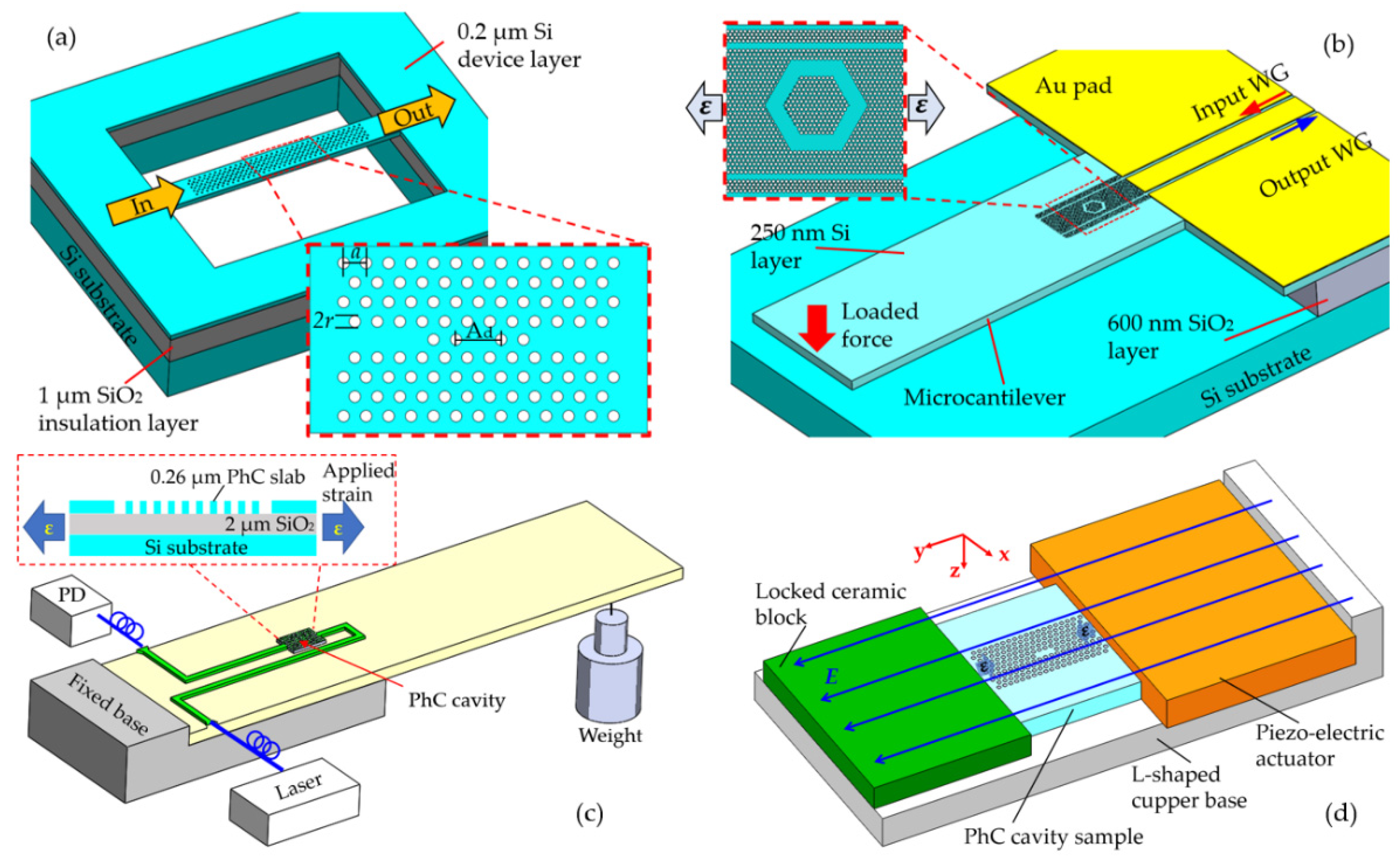
3.2.1. Deformable Cavity-Based PhC Sensors
3.2.2. Near-Field Probe Perturbation-Based PhC Sensors
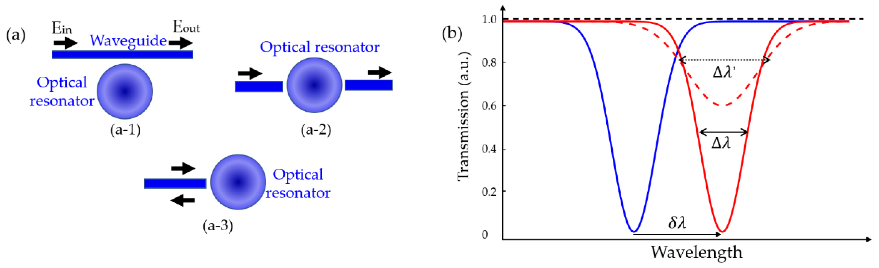
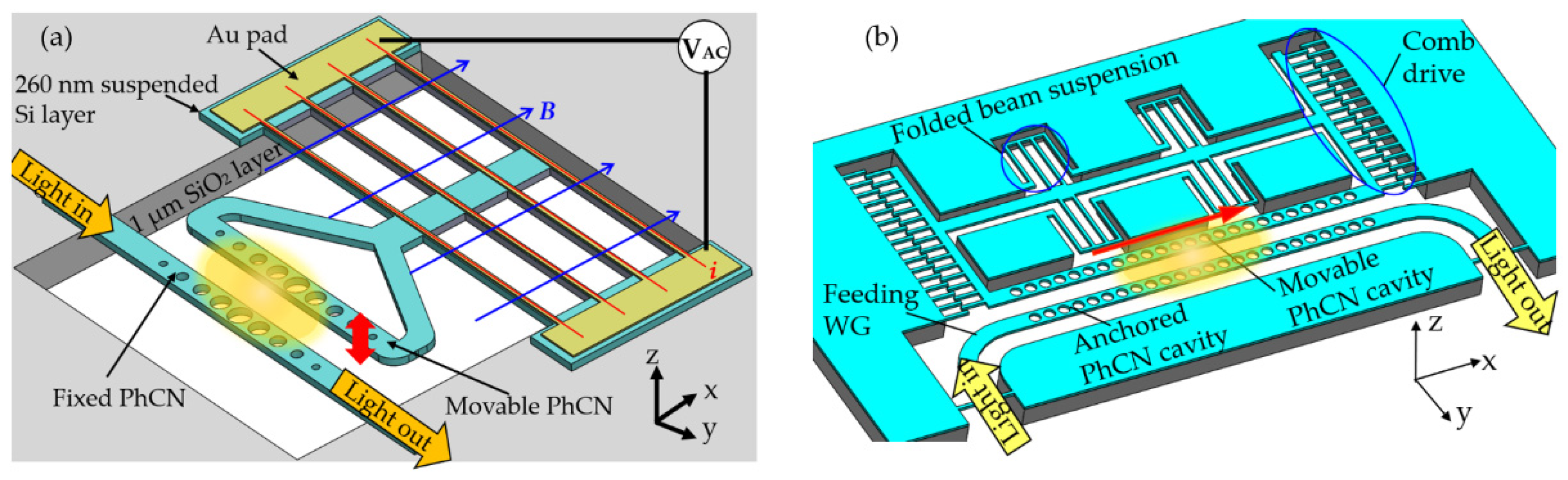
3.2.3. Mode-Splitting Based Coupled PhC Sensors
3.3. Discussion
4. Radiation Pressure-Driven PhC Cavity Sensors
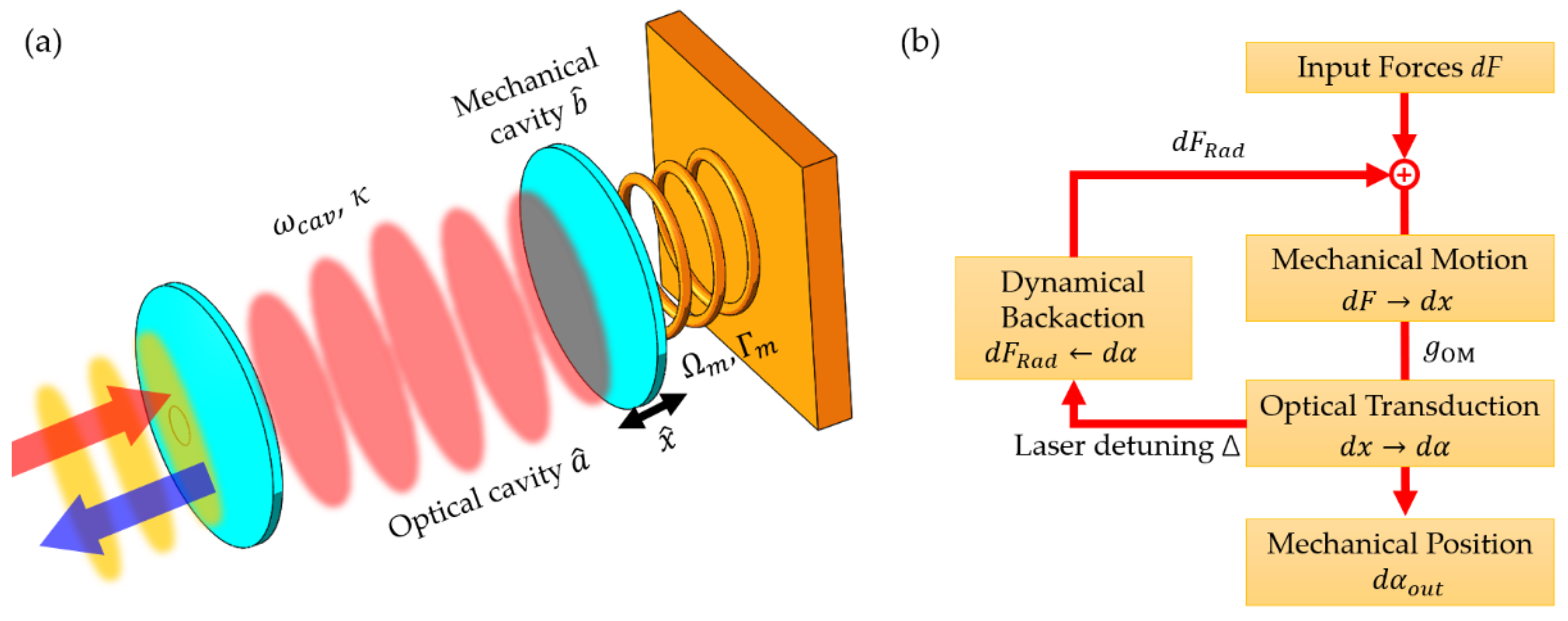
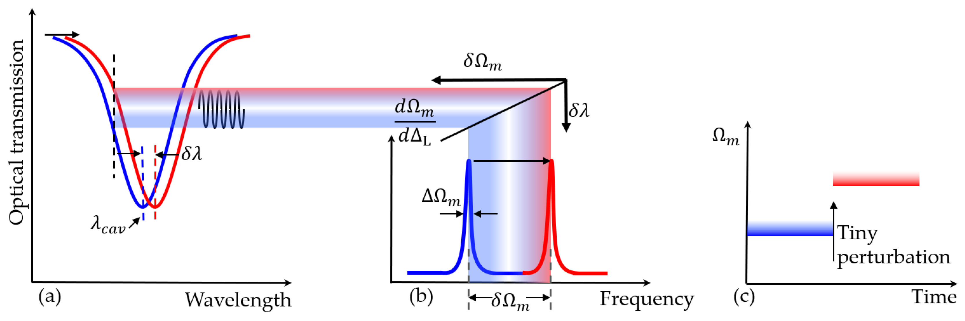
4.1. Optomehanical Effects for Sensing Applications
4.2. Sensing Applications Based on Radiation Pressure
4.2.1. Displacement Sensing
4.2.2. Force Sensing
4.2.3. Mass Sensing
4.2.4. Inertial Sensing
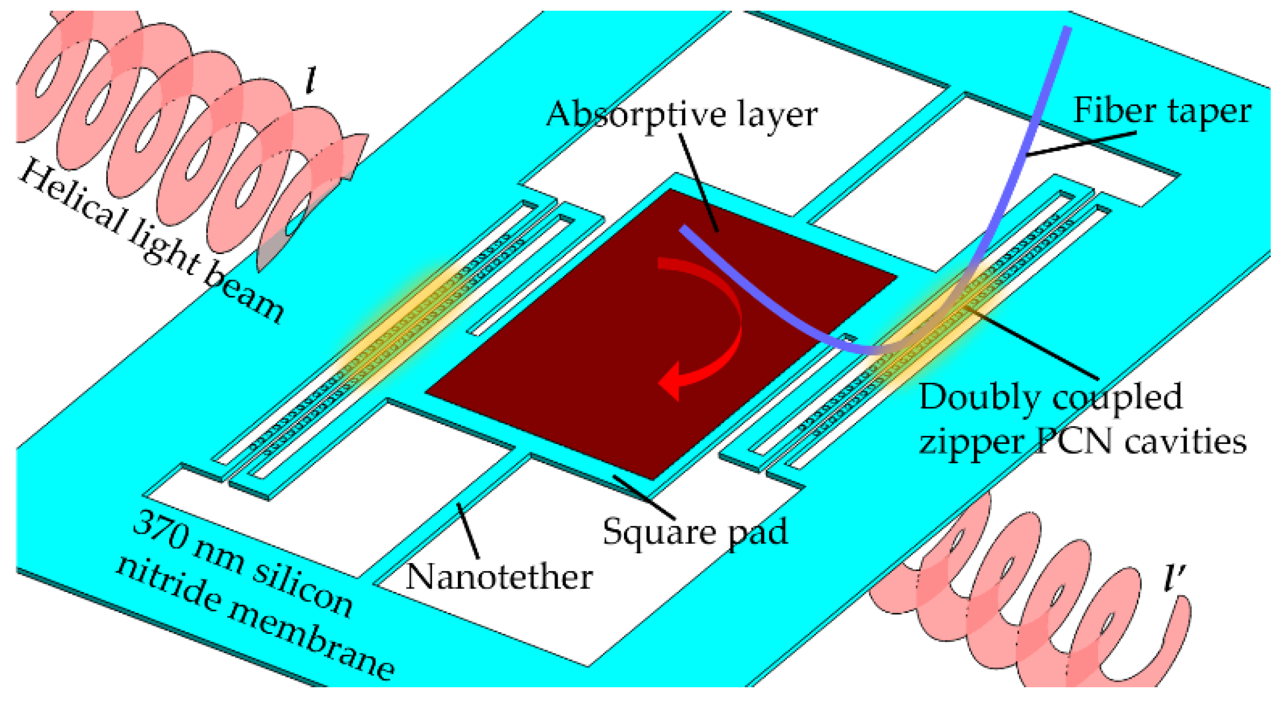
4.2.5. Optomechanical Detection on Angular Momentum of Light
4.2.6. Summary of Radiation Pressure-Driven PhC Cavity Sensors
4.3. Future Perspectives for Optomechanical Sensing Based on PhC Cavities
4.3.1. Nonlinear Optomechanics Enhanced Sensitivity
4.3.2. Two-Dimensional Materials Integrated with Optomechanical Systems
5. Summary and Outlook
Author Contributions
Funding
Conflicts of Interest
References
- Ma, J.; Povinelli, M.L. Applications of optomechanical effects for on-chip manipulation of light signals. Curr. Opin. Solid State Mater. Sci. 2012, 16, 82–90. [Google Scholar] [CrossRef]
- Notomi, M. Manipulating light with strongly modulated photonic crystals. Rep. Prog. Phys. 2010, 73, 096501. [Google Scholar] [CrossRef]
- Midolo, L.; Schliesser, A.; Fiore, A. Nano-opto-electro-mechanical systems. Nat. Nanotechnol. 2018, 13, 11–18. [Google Scholar] [CrossRef] [PubMed] [Green Version]
- Lončar, M. Opto-mechanical interaction in flexible photonic crystals. In Proceedings of the Laser Science, Orlando, FL, USA, 6–10 October; p. LTh3G.1.
- Du, H.; Chau, F.S.; Zhou, G. Mechanically-Tunable Photonic Devices with On-Chip Integrated MEMS/NEMS Actuators. Micromachines 2016, 7, 69. [Google Scholar] [CrossRef] [PubMed] [Green Version]
- Hadzialic, S.; Kim, S.; Sarioglu, A.F.; Sudbø, A.S.; Solgaard, O. Displacement sensing with a mechanically tunable photonic crystal. IEEE Photonics Technol. Lett. 2010, 22, 1196–1198. [Google Scholar] [CrossRef]
- Edinger, P.; Errando-Herranz, C.; Takabayashi, A.Y.; Sattari, H.; Quack, N.; Verheyen, P.; Bogaerts, W.; Gylfason, K.B. Compact low loss MEMS phase shifters for scalable field-programmable silicon photonics. In Proceedings of the CLEO: Science and Innovations, Washington, DC, USA, 10–15 May 2020; p. SM3J.2. [Google Scholar]
- Chew, X.; Zhou, G.; Yu, H.; Chau, F.S.; Deng, J.; Loke, Y.C.; Tang, X. An in-plane nano-mechanics approach to achieve reversible resonance control of photonic crystal nanocavities. Opt. Express 2010, 18, 22232–22244. [Google Scholar] [CrossRef]
- Yang, D.; Tian, H.; Ji, Y. Microdisplacement sensor based on high-Q nanocavity in slot photonic crystal. Opt. Eng. 2011, 50, 054402. [Google Scholar] [CrossRef]
- Galeotti, F.; Seršić Vollenbroek, I.; Petruzzella, M.; Pagliano, F.; van Otten, F.W.; Zobenica, Ž.; Mohtashami, A.; Marnani, H.S.; van der Heijden, R.W.; Fiore, A. On-chip waveguide-coupled opto-electro-mechanical system for nanoscale displacement sensing. APL Photonics 2020, 5, 026103. [Google Scholar] [CrossRef] [Green Version]
- Li, B.; Lee, C. NEMS diaphragm sensors integrated with triple-nano-ring resonator. Sens. Actuators A Phys. 2011, 172, 61–68. [Google Scholar] [CrossRef]
- Lu, T.W.; Lee, P.T. Ultra-high sensitivity optical stress sensor based on double-layered photonic crystal microcavity. Opt. Express 2009, 17, 1518–1526. [Google Scholar] [CrossRef]
- Rogers, D.J.; Papadakis, S.J.; Churchill, L.R.; Wong, C.W. Chip-Scale Optomechanical Magnetometer. U.S. Patent No. 9,897,666, 20 February 2018. [Google Scholar]
- Du, H.; Zhou, G.; Zhao, Y.; Chen, G.; Chau, F.S. Magnetic field sensor based on coupled photonic crystal nanobeam cavities. Appl. Phys. Lett. 2017, 110, 061110. [Google Scholar] [CrossRef]
- Sun, S.; Kim, H.; Solomon, G.S.; Waks, E. Strain tuning of a quantum dot strongly coupled to a photonic crystal cavity. Appl. Phys. Lett. 2013, 103, 151102. [Google Scholar] [CrossRef] [Green Version]
- Rogers, B.; Gullo, N.L.; De Chiara, G.; Palma, G.M.; Paternostro, M. Hybrid optomechanics for quantum technologies. Quantum Meas. Quantum Metrol. 2014, 2, 11–43. [Google Scholar] [CrossRef]
- Aspelmeyer, M.; Kippenberg, T.J.; Marquardt, F. Cavity optomechanics. Rev. Mod. Phys. 2014, 86, 1391. [Google Scholar] [CrossRef]
- Liu, Y.-C.; Xiao, Y.-F.; Luan, X.; Gong, Q.; Wong, C.W. Coupled cavities for motional ground-state cooling and strong optomechanical coupling. Phys. Rev. A 2015, 91, 033818. [Google Scholar] [CrossRef] [Green Version]
- Teufel, J.D.; Donner, T.; Li, D.; Harlow, J.W.; Allman, M.S.; Cicak, K.; Sirois, A.J.; Whittaker, J.D.; Lehnert, K.W.; Simmonds, R.W. Sideband cooling of micromechanical motion to the quantum ground state. Nature 2011, 475, 359–363. [Google Scholar] [CrossRef] [Green Version]
- Teufel, J.D.; Donner, T.; Castellanos-Beltran, M.; Harlow, J.W.; Lehnert, K.W. Nanomechanical motion measured with an imprecision below that at the standard quantum limit. Nat. Nanotechnol. 2009, 4, 820–823. [Google Scholar] [CrossRef]
- Hu, Y.-W.; Xiao, Y.-F.; Liu, Y.-C.; Gong, Q. Optomechanical sensing with on-chip microcavities. Front. Phys. 2013, 8, 475–490. [Google Scholar] [CrossRef]
- Metcalfe, M. Applications of cavity optomechanics. Appl. Phys. Rev. 2014, 1, 031105. [Google Scholar] [CrossRef]
- Corbitt, T.; Ottaway, D.; Innerhofer, E.; Pelc, J.; Mavalvala, N. Measurement of radiation-pressure-induced optomechanical dynamics in a suspended Fabry-Perot cavity. Phys. Rev. A 2006, 74, 021802. [Google Scholar] [CrossRef] [Green Version]
- Schliesser, A.; Kippenberg, T.J. Cavity optomechanics with whispering-gallery mode optical micro-resonators. In Advances in Atomic, Molecular, and Optical Physics; Elsevier: Amsterdam, The Netherlands, 2010; Volume 58, pp. 207–323. [Google Scholar]
- Kim, S.H.; Lee, K.-D.; Kim, J.-Y.; Kwon, M.-K.; Park, S.-J. Fabrication of photonic crystal structures on light emitting diodes by nanoimprint lithography. Nanotechnology 2007, 18, 055306. [Google Scholar] [CrossRef]
- Thorhauge, M.; Frandsen, L.H.; Borel, P.I. Efficient photonic crystal directional couplers. Opt. Lett. 2003, 28, 1525–1527. [Google Scholar] [CrossRef] [PubMed]
- Threm, D.; Nazirizadeh, Y.; Gerken, M. Photonic crystal biosensors towards on-chip integration. J. Biophotonics 2012, 5, 601–616. [Google Scholar] [CrossRef]
- Goyal, A.K.; Dutta, H.S.; Pal, S. Recent advances and progress in photonic crystal-based gas sensors. J. Phys. D: Appl. Phys. 2017, 50, 203001. [Google Scholar] [CrossRef]
- Qiao, Q.; Xia, J.; Lee, C.; Zhou, G. Applications of Photonic Crystal Nanobeam Cavities for Sensing. Micromachines 2018, 9, 541. [Google Scholar] [CrossRef] [PubMed] [Green Version]
- Yang, D.Q.; Duan, B.; Liu, X.; Wang, A.Q.; Li, X.G.; Ji, Y.F. Photonic Crystal Nanobeam Cavities for Nanoscale Optical Sensing: A Review. Micromachines 2020, 11, 72. [Google Scholar] [CrossRef] [PubMed] [Green Version]
- Kippenberg, T.J.; Vahala, K.J. Cavity optomechanics: Back-action at the mesoscale. Science 2008, 321, 1172–1176. [Google Scholar] [CrossRef] [Green Version]
- Yong-Chun, L.; Yu-Wen, H.; Wei, W.C.; Yun-Feng, X. Review of cavity optomechanical cooling. Chin. Phys. B 2013, 22, 114213. [Google Scholar]
- Favero, I.; Marquardt, F. Focus on optomechanics. New J. Phys. 2014, 16, 085006. [Google Scholar] [CrossRef]
- Xiong, H.; Si, L.; Lv, X.; Yang, X.; Wu, Y. Review of cavity optomechanics in the weak-coupling regime: From linearization to intrinsic nonlinear interactions. Sci. China Phys. Mech. Astron. 2015, 58, 1–13. [Google Scholar] [CrossRef]
- Hossein-Zadeh, M.; Vahala, K.J. An optomechanical oscillator on a silicon chip. IEEE J. Sel. Top. Quantum Electron. 2009, 16, 276–287. [Google Scholar] [CrossRef] [Green Version]
- Liu, Y.-l.; Wang, C.; Zhang, J.; Liu, Y.-x. Cavity optomechanics: Manipulating photons and phonons towards the single-photon strong coupling. Chin. Phys. B 2018, 27, 024204. [Google Scholar] [CrossRef]
- Zhao, Y.; Zhang, Y.-N.; Wang, Q.; Hu, H. Review on the optimization methods of slow light in photonic crystal waveguide. IEEE Trans. Nanotechnol. 2015, 14, 407–426. [Google Scholar] [CrossRef]
- Dutta, H.S.; Goyal, A.K.; Srivastava, V.; Pal, S. Coupling light in photonic crystal waveguides: A review. Photonics Nanostruct.-Fundam. Appl. 2016, 20, 41–58. [Google Scholar] [CrossRef]
- Notomi, M.; Kuramochi, E.; Taniyama, H. Ultrahigh-Q nanocavity with 1D photonic gap. Opt. Express 2008, 16, 11095–11102. [Google Scholar] [CrossRef]
- Song, B.-S.; Noda, S.; Asano, T.; Akahane, Y. Ultra-high-Q photonic double-heterostructure nanocavity. Nat. Mater. 2005, 4, 207–210. [Google Scholar] [CrossRef]
- Ogawa, S.; Imada, M.; Yoshimoto, S.; Okano, M.; Noda, S. Control of light emission by 3D photonic crystals. Science 2004, 305, 227–229. [Google Scholar] [CrossRef]
- Chew, X.; Zhou, G.; Chau, F.S.; Deng, J. Enhanced resonance tuning of photonic crystal nanocavities by integration of optimized near-field multitip nanoprobes. J. Nanophotonics 2011, 5, 059503. [Google Scholar] [CrossRef]
- Chan, J.; Safavi-Naeini, A.H.; Hill, J.T.; Meenehan, S.; Painter, O. Optimized optomechanical crystal cavity with acoustic radiation shield. Appl. Phys. Lett. 2012, 101, 081115. [Google Scholar] [CrossRef] [Green Version]
- Tian, F.; Sumikura, H.; Kuramochi, E.; Taniyama, H.; Takiguchi, M.; Notomi, M. Optomechanical oscillator pumped and probed by optically two isolated photonic crystal cavity systems. Opt. Express 2016, 24, 28039–28055. [Google Scholar] [CrossRef]
- Eichenfield, M.; Camacho, R.; Chan, J.; Vahala, K.J.; Painter, O. A picogram-and nanometre-scale photonic-crystal optomechanical cavity. Nature 2009, 459, 550–555. [Google Scholar] [CrossRef] [PubMed] [Green Version]
- Hryciw, A.C.; Wu, M.; Khanaliloo, B.; Barclay, P.E. Tuning of nanocavity optomechanical coupling using a near-field fiber probe. Optica 2015, 2, 491–496. [Google Scholar] [CrossRef]
- Leijssen, R.; Verhagen, E. Strong optomechanical interactions in a sliced photonic crystal nanobeam. Sci. Rep. 2015, 5, 15974. [Google Scholar] [CrossRef] [PubMed] [Green Version]
- Schneider, K.; Seidler, P. Strong optomechanical coupling in a slotted photonic crystal nanobeam cavity with an ultrahigh quality factor-to-mode volume ratio. Opt. Express 2016, 24, 13850–13865. [Google Scholar] [CrossRef] [PubMed] [Green Version]
- Chew, X.; Zhou, G.; Chau, F.S.; Deng, J.; Tang, X.; Loke, Y.C. Dynamic tuning of an optical resonator through MEMS-driven coupled photonic crystal nanocavities. Opt. Lett. 2010, 35, 2517–2519. [Google Scholar] [CrossRef] [PubMed]
- Tian, F.; Zhou, G.; Du, Y.; Chau, F.S.; Deng, J.; Teo, S.L.; Akkipeddi, R. Nanoelectromechanical-systems-controlled bistability of double-coupled photonic crystal cavities. Opt. Lett. 2013, 38, 3394–3397. [Google Scholar] [CrossRef]
- Tian, F.; Zhou, G.; Siong Chau, F.; Deng, J.; Akkipeddi, R. Measurement of coupled cavities’ optomechanical coupling coefficient using a nanoelectromechanical actuator. Appl. Phys. Lett. 2013, 102, 081101. [Google Scholar] [CrossRef]
- Tian, F.; Zhou, G.; Du, Y.; Chau, F.S.; Deng, J.; Tang, X.; Akkipeddi, R. Energy-efficient utilization of bipolar optical forces in nano-optomechanical cavities. Opt. Express 2013, 21, 18398–18407. [Google Scholar] [CrossRef]
- Du, H.; Zhang, X.; Chen, G.; Deng, J.; Chau, F.S.; Zhou, G. Precise control of coupling strength in photonic molecules over a wide range using nanoelectromechanical systems. Sci. Rep. 2016, 6, 24766. [Google Scholar] [CrossRef] [Green Version]
- Du, H.; Zhang, X.; Deng, J.; Zhao, Y.; Chau, F.S.; Zhou, G. Lateral shearing optical gradient force in coupled nanobeam photonic crystal cavities. Appl. Phys. Lett. 2016, 108, 171102. [Google Scholar] [CrossRef]
- Tian, F.; Zhou, G.; Chau, F.S.; Deng, J. Torsional optical spring effect in coupled nanobeam photonic crystal cavities. Opt. Lett. 2014, 39, 6289–6292. [Google Scholar] [CrossRef] [PubMed]
- Tian, F.; Zhou, G.; Du, Y.; Chau, F.S.; Deng, J.; Akkipeddi, R. Out-of-plane nanomechanical tuning of double-coupled one-dimensional photonic crystal cavities. Opt. Lett. 2013, 38, 2005–2007. [Google Scholar] [CrossRef] [PubMed]
- Midolo, L.; Yoon, S.N.; Pagliano, F.; Xia, T.; van Otten, F.W.; Lermer, M.; Hofling, S.; Fiore, A. Electromechanical tuning of vertically-coupled photonic crystal nanobeams. Opt. Express 2012, 20, 19255–19263. [Google Scholar] [CrossRef] [PubMed] [Green Version]
- Cui, X.; Zhang, W.; Zhang, J.; Le Roux, X.; Alonso-Ramos, C.; Vivien, L.; He, J.-J.; Cassan, E. Tailoring mode splitting and degeneracy in silicon triply resonant nanobeam cavities. JOSA B 2019, 36, 1267–1272. [Google Scholar] [CrossRef]
- Grutter, K.E.; Davanço, M.I.; Balram, K.C.; Srinivasan, K. Invited Article: Tuning and stabilization of optomechanical crystal cavities through NEMS integration. APL Photonics 2018, 3, 100801. [Google Scholar] [CrossRef] [Green Version]
- Deotare, P.B.; Bulu, I.; Frank, I.W.; Quan, Q.; Zhang, Y.; Ilic, R.; Loncar, M. All optical reconfiguration of optomechanical filters. Nat. Commun. 2012, 3, 846. [Google Scholar] [CrossRef]
- Cohen, J.D.; Meenehan, S.M.; Painter, O. Optical coupling to nanoscale optomechanical cavities for near quantum-limited motion transduction. Opt. Express 2013, 21, 11227–11236. [Google Scholar] [CrossRef] [Green Version]
- Camacho, R.M.; Chan, J.; Eichenfield, M.; Painter, O. Characterization of radiation pressure and thermal effects in a nanoscale optomechanical cavity. Opt. Express 2009, 17, 15726–15735. [Google Scholar] [CrossRef] [Green Version]
- Perahia, R.; Cohen, J.; Meenehan, S.; Alegre, T.M.; Painter, O. Electrostatically tunable optomechanical “zipper” cavity laser. Appl. Phys. Lett. 2010, 97, 191112. [Google Scholar] [CrossRef] [Green Version]
- Westendorp, S. Cavity Optomechanics in Vertically-Coupled Photonic Crystal Nanobeams and Membranes. Ph.D. Thesis, Eindhoven University of Technology, Eindhoven, The Netherlands, 2014. [Google Scholar]
- Lin, T.; Tian, F.; Shi, P.; Chau, F.S.; Zhou, G.; Tang, X.; Deng, J. Design of mechanically-tunable photonic crystal split-beam nanocavity. Opt. Lett. 2015, 40, 3504–3507. [Google Scholar] [CrossRef]
- Shi, P.; Du, H.; Chau, F.S.; Zhou, G.; Deng, J. Tuning the quality factor of split nanobeam cavity by nanoelectromechanical systems. Opt. Express 2015, 23, 19338–19347. [Google Scholar] [CrossRef] [PubMed]
- Lin, T.; Zhang, X.; Zou, Y.; Chau, F.S.; Deng, J.; Zhou, G. Out-of-plane nano-electro-mechanical tuning of the Fano resonance in photonic crystal split-beam nanocavity. Appl. Phys. Lett. 2015, 107, 153107. [Google Scholar] [CrossRef]
- Tian, F.; Zhou, G.; Chau, F.S.; Deng, J.; Du, Y.; Tang, X.; Akkipeddi, R.; Loke, Y.C. Tuning of split-ladder cavity by its intrinsic nano-deformation. Opt. Express 2012, 20, 27697–27707. [Google Scholar] [CrossRef] [PubMed]
- Miri, M.; Sodagar, M.; Eftekhar, A.; Mehrany, K.; Rashidian, B.; Adibi, A. Wideband tunable photonic crystal cavity with electrostatic actuation. In Proceedings of the IEEE Photonics Conference, Burlingame, CA, USA, 23–27 September 2012; pp. 266–267. [Google Scholar]
- Wu, M.; Wu, N.L.; Firdous, T.; Fani Sani, F.; Losby, J.E.; Freeman, M.R.; Barclay, P.E. Nanocavity optomechanical torque magnetometry and radiofrequency susceptometry. Nat. Nanotechnol. 2017, 12, 127–131. [Google Scholar] [CrossRef] [PubMed]
- Seidler, P.; Lister, K.; Drechsler, U.; Hofrichter, J.; Stoferle, T. Slotted photonic crystal nanobeam cavity with an ultrahigh quality factor-to-mode volume ratio. Opt. Express 2013, 21, 32468–32483. [Google Scholar] [CrossRef]
- Li, B.; Hsiao, F.-L.; Lee, C. Configuration analysis of sensing element for photonic crystal based NEMS cantilever using dual nano-ring resonator. Sens. Actuators A Phys. 2011, 169, 352–361. [Google Scholar] [CrossRef]
- Mai, T.T.; Hsiao, F.-L.; Lee, C.; Xiang, W.; Chen, C.-C.; Choi, W. Optimization and comparison of photonic crystal resonators for silicon microcantilever sensors. Sens. Actuators A Phys. 2011, 165, 16–25. [Google Scholar] [CrossRef]
- Abdulla, S.C.; Kauppinen, L.; Dijkstra, M.; de Boer, M.J.; Berenschot, E.; de Ridder, R.; Krijnen, G.J. Micro-cantilever integrated 2D photonic crystal slab waveguide for enhanced dispersion tuning. J. Micromech. Microeng. 2011, 21, 125010. [Google Scholar] [CrossRef]
- Gao, J.; McMillan, J.F.; Wu, M.-C.; Zheng, J.; Assefa, S.; Wong, C.W. Demonstration of an air-slot mode-gap confined photonic crystal slab nanocavity with ultrasmall mode volumes. Appl. Phys. Lett. 2010, 96, 051123. [Google Scholar] [CrossRef] [Green Version]
- Pitanti, A.; Fink, J.M.; Safavi-Naeini, A.H.; Hill, J.T.; Lei, C.U.; Tredicucci, A.; Painter, O. Strong opto-electro-mechanical coupling in a silicon photonic crystal cavity. Opt. Express 2015, 23, 3196–3208. [Google Scholar] [CrossRef] [Green Version]
- Mao, D.; Liu, P.; Ho, K.-M.; Dong, L. A theoretical study of a nano-opto-mechanical sensor using a photonic crystal-cantilever cavity. J. Opt. 2012, 14, 075002. [Google Scholar] [CrossRef]
- Wang, Q.; Mao, D.; Dong, L. MEMS Tunable Photonic Crystal-Cantilever Cavity. J. Microelectromech. Syst. 2019, 28, 741–743. [Google Scholar] [CrossRef]
- Midolo, L.; Pagliano, F.; Hoang, T.; Xia, T.; van Otten, F.; Li, L.; Linfield, E.; Lermer, M.; Höfling, S.; Fiore, A. Spontaneous emission control of single quantum dots by electromechanical tuning of a photonic crystal cavity. Appl. Phys. Lett. 2012, 101, 091106. [Google Scholar] [CrossRef] [Green Version]
- Roh, Y.-G.; Tanabe, T.; Shinya, A.; Taniyama, H.; Kuramochi, E.; Matsuo, S.; Sato, T.; Notomi, M. Strong optomechanical interaction in a bilayer photonic crystal. Phys. Rev. B 2010, 81, 121101. [Google Scholar] [CrossRef]
- Gavartin, E.; Braive, R.; Sagnes, I.; Arcizet, O.; Beveratos, A.; Kippenberg, T.J.; Robert-Philip, I. Optomechanical coupling in a two-dimensional photonic crystal defect cavity. Phys. Rev. Lett. 2011, 106, 203902. [Google Scholar] [CrossRef] [PubMed] [Green Version]
- Winger, M.; Blasius, T.D.; Mayer Alegre, T.P.; Safavi-Naeini, A.H.; Meenehan, S.; Cohen, J.; Stobbe, S.; Painter, O. A chip-scale integrated cavity-electro-optomechanics platform. Opt. Express 2011, 19, 24905–24921. [Google Scholar] [CrossRef] [PubMed] [Green Version]
- Zheng, J.; Sun, X.; Li, Y.; Poot, M.; Dadgar, A.; Shi, N.N.; Pernice, W.H.; Tang, H.X.; Wong, C.W. Femtogram dispersive L3-nanobeam optomechanical cavities: Design and experimental comparison. Opt. Express 2012, 20, 26486–26498. [Google Scholar] [CrossRef] [PubMed]
- Antoni, T.; Kuhn, A.G.; Briant, T.; Cohadon, P.F.; Heidmann, A.; Braive, R.; Beveratos, A.; Abram, I.; Le Gratiet, L.; Sagnes, I.; et al. Deformable two-dimensional photonic crystal slab for cavity optomechanics. Opt. Lett. 2011, 36, 3434–3436. [Google Scholar] [CrossRef] [Green Version]
- Safavi-Naeini, A.H.; Alegre, T.P.M.; Winger, M.; Painter, O. Optomechanics in an ultrahigh-Q two-dimensional photonic crystal cavity. Appl. Phys. Lett. 2010, 97, 181106. [Google Scholar] [CrossRef] [Green Version]
- Sun, X.; Zheng, J.; Poot, M.; Wong, C.W.; Tang, H.X. Femtogram doubly clamped nanomechanical resonators embedded in a high-Q two-dimensional photonic crystal nanocavity. Nano Lett. 2012, 12, 2299–2305. [Google Scholar] [CrossRef]
- Meade, R.; Winn, J.N.; Joannopoulos, J. Photonic Crystals: Molding the Flow of Light; Princeton University Press: Princeton, NJ, USA, 1995. [Google Scholar]
- Faraon, A.; Waks, E.; Englund, D.; Fushman, I.; Vučković, J. Efficient photonic crystal cavity-waveguide couplers. Appl. Phys. Lett. 2007, 90, 073102. [Google Scholar] [CrossRef] [Green Version]
- Yang, D.; Tian, H.; Wu, N.; Yang, Y.; Ji, Y. Nanoscale torsion-free photonic crystal pressure sensor with ultra-high sensitivity based on side-coupled piston-type microcavity. Sens. Actuators A Phys. 2013, 199, 30–36. [Google Scholar] [CrossRef]
- Talneau, A.; Mulot, M.; Anand, S.; Lalanne, P. Compound cavity measurement of transmission and reflection of a tapered single-line photonic-crystal waveguide. Appl. Phys. Lett. 2003, 82, 2577–2579. [Google Scholar] [CrossRef] [Green Version]
- Johnson, S.G.; Ibanescu, M.; Skorobogatiy, M.; Weisberg, O.; Joannopoulos, J.; Fink, Y. Perturbation theory for Maxwell’s equations with shifting material boundaries. Phys. Rev. E 2002, 65, 066611. [Google Scholar] [CrossRef] [PubMed] [Green Version]
- Quan, Q.; Floyd, D.L.; Burgess, I.B.; Deotare, P.B.; Frank, I.W.; Tang, S.K.; Ilic, R.; Loncar, M. Single particle detection in CMOS compatible photonic crystal nanobeam cavities. Opt. Express 2013, 21, 32225–32233. [Google Scholar] [CrossRef] [PubMed]
- Liang, F.; Quan, Q. Detecting single gold nanoparticles (1.8 nm) with ultrahigh-Q air-mode photonic crystal nanobeam cavities. ACS Photonics 2015, 2, 1692–1697. [Google Scholar] [CrossRef]
- Lin, S.; Crozier, K.B. Trapping-assisted sensing of particles and proteins using on-chip optical microcavities. ACS Nano 2013, 7, 1725–1730. [Google Scholar] [CrossRef] [PubMed]
- Li, Q.; Wang, T.; Su, Y.; Yan, M.; Qiu, M. Coupled mode theory analysis of mode-splitting in coupled cavity system. Opt. Express 2010, 18, 8367–8382. [Google Scholar] [CrossRef]
- Jiang, W.; Mayor, F.M.; Patel, R.N.; McKenna, T.P.; Sarabalis, C.J.; Safavi-Naeini, A.H. Nanobenders: Efficient piezoelectric actuators for widely tunable nanophotonics at CMOS-level voltages. arXiv 2019, arXiv:1911.10973. [Google Scholar]
- Lee, C.; Radhakrishnan, R.; Chen, C.-C.; Li, J.; Thillaigovindan, J.; Balasubramanian, N. Design and modeling of a nanomechanical sensor using silicon photonic crystals. J. Lightwave Technol. 2008, 26, 839–846. [Google Scholar] [CrossRef] [Green Version]
- Tung, B.T.; Dao, D.V.; Ikeda, T.; Kanamori, Y.; Hane, K.; Sugiyama, S. Investigation of strain sensing effect in modified single-defect photonic crystal nanocavity. Opt. Express 2011, 19, 8821–8829. [Google Scholar] [CrossRef] [PubMed] [Green Version]
- Tung, B.T.; Dao, D.V.; Ikeda, T.; Kanamori, Y.; Hane, K.; Sugiyama, S. Longitudinal strain sensitive effect in a photonic crystal cavity. Procedia Eng. 2011, 25, 1357–1360. [Google Scholar] [CrossRef] [Green Version]
- Yang, Y.; Tian, H.; Yang, D.; Wu, N.; Zhou, J.; Liu, Q.; Ji, Y. Nanomechanical three dimensional force photonic crystal sensor using shoulder-coupled resonant cavity with an inserted pillar. Sens. Actuators A Phys. 2014, 209, 33–40. [Google Scholar] [CrossRef]
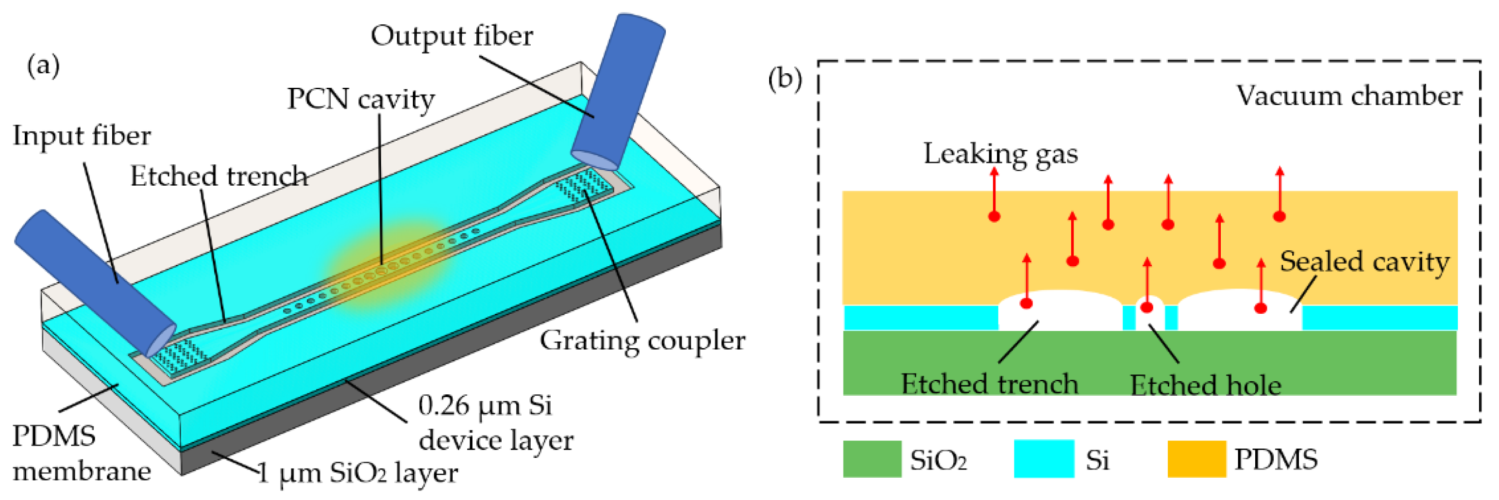
- Qiao, Q.; Peng, C.; Xia, J.; Lee, C.; Zhou, G. Ultra-small photonic crystal (PhC)-based test tool for gas permeability of polymers. Opt. Express 2019, 27, 35600–35608. [Google Scholar] [CrossRef] [PubMed]
- Petruzzella, M.; La China, F.; Intonti, F.; Caselli, N.; De Pas, M.; van Otten, F.; Gurioli, M.; Fiore, A. Nanoscale mechanical actuation and near-field read-out of photonic crystal molecules. Phys. Rev. B 2016, 94, 115413. [Google Scholar] [CrossRef] [Green Version]
- Zobenica, Ž.; van der Heijden, R.; Petruzzella, M.; Pagliano, F.; Leijssen, R.; Xia, T.; Midolo, L.; Cotrufo, M.; Cho, Y.J.; van Otten, F. Fully integrated nano-opto-electro-mechanical wavelength and displacement sensor. In Proceedings of the Optical Sensors, Vancouver, BC, Canada, 18–20 July 2016; p. SeW2E.4. [Google Scholar]
- Zhu, Y.; Lee, J.; Seshia, A. System-level simulation of a micromachined electrometer using a time-domain variable capacitor circuit model. J. Micromech. Microeng. 2007, 17, 1059. [Google Scholar] [CrossRef] [Green Version]
- Rosenberg, J.; Lin, Q.; Painter, O. Static and dynamic wavelength routing via the gradient optical force. Nat. Photonics 2009, 3, 478–483. [Google Scholar] [CrossRef]
- Berman, P.R.; Lin, C.C.; Arimondo, E. Advances in Atomic, Molecular, and Optical Physics; Elsevier: Amsterdam, The Netherlands, 2006. [Google Scholar]
- Wiederhecker, G.S.; Chen, L.; Gondarenko, A.; Lipson, M. Controlling photonic structures using optical forces. Nature 2009, 462, 633–636. [Google Scholar] [CrossRef] [PubMed]
- Yu, W.; Jiang, W.C.; Lin, Q.; Lu, T. Cavity optomechanical spring sensing of single molecules. Nat. Commun. 2016, 7, 12311. [Google Scholar] [CrossRef]
- Pan, F.; Cui, K.; Bai, G.; Feng, X.; Liu, F.; Zhang, W.; Huang, Y. Radiation-Pressure-Antidamping Enhanced Optomechanical Spring Sensing. ACS Photonics 2018, 5, 4164–4169. [Google Scholar] [CrossRef]
- Black, E.D. An introduction to Pound–Drever–Hall laser frequency stabilization. Am. J. Phys. 2001, 69, 79–87. [Google Scholar] [CrossRef] [Green Version]
- Anetsberger, G.; Gavartin, E.; Arcizet, O.; Unterreithmeier, Q.P.; Weig, E.M.; Gorodetsky, M.L.; Kotthaus, J.P.; Kippenberg, T.J. Measuring nanomechanical motion with an imprecision below the standard quantum limit. Phys. Rev. A 2010, 82, 061804. [Google Scholar] [CrossRef] [Green Version]
- Safavi-Naeini, A.H.; Groblacher, S.; Hill, J.T.; Chan, J.; Aspelmeyer, M.; Painter, O. Squeezed light from a silicon micromechanical resonator. Nature 2013, 500, 185–189. [Google Scholar] [CrossRef] [Green Version]
- Khanaliloo, B.; Jayakumar, H.; Hryciw, A.C.; Lake, D.P.; Kaviani, H.; Barclay, P.E. Single-crystal diamond nanobeam waveguide optomechanics. Phys. Rev. X 2015, 5, 041051. [Google Scholar] [CrossRef] [Green Version]
- Burek, M.J.; Chu, Y.; Liddy, M.S.; Patel, P.; Rochman, J.; Meesala, S.; Hong, W.; Quan, Q.; Lukin, M.D.; Loncar, M. High quality-factor optical nanocavities in bulk single-crystal diamond. Nat. Commun. 2014, 5, 5718. [Google Scholar] [CrossRef] [PubMed]
- Lu, X.; Lee, J.Y.; Lin, Q. Silicon carbide zipper photonic crystal optomechanical cavities. Appl. Phys. Lett. 2020, 116, 221104. [Google Scholar] [CrossRef] [PubMed]
- Lee, J.Y.; Lu, X.; Lin, Q. High-Q silicon carbide photonic-crystal cavities. Appl. Phys. Lett. 2015, 106, 041106. [Google Scholar] [CrossRef]
- Kaviani, H.; Healey, C.; Wu, M.; Ghobadi, R.; Hryciw, A.; Barclay, P.E. Nonlinear optomechanical paddle nanocavities. Optica 2015, 2, 271–274. [Google Scholar] [CrossRef] [Green Version]
- Healey, C.; Kaviani, H.; Wu, M.; Khanaliloo, B.; Mitchell, M.; Hryciw, A.C.; Barclay, P.E. Design and experimental demonstration of optomechanical paddle nanocavities. Appl. Phys. Lett. 2015, 107, 231107. [Google Scholar] [CrossRef] [Green Version]
- Healey, C.; Kaviani, H.; Barclay, P.E. Air mode silicon nitride photonic crystals and their application to nonlinear quantum optomechanical sensing. arXiv 2019, arXiv:1905.03341. [Google Scholar]
- Paraïso, T.K.; Kalaee, M.; Zang, L.; Pfeifer, H.; Marquardt, F.; Painter, O. Position-squared coupling in a tunable photonic crystal optomechanical cavity. Phys. Rev. X 2015, 5, 041024. [Google Scholar] [CrossRef] [Green Version]
- Doolin, C.; Hauer, B.; Kim, P.; MacDonald, A.; Ramp, H.; Davis, J. Nonlinear optomechanics in the stationary regime. Phys. Rev. A 2014, 89, 053838. [Google Scholar] [CrossRef] [Green Version]
- Luan, X.; Huang, Y.; Li, Y.; McMillan, J.F.; Zheng, J.; Huang, S.W.; Hsieh, P.C.; Gu, T.; Wang, D.; Hati, A.; et al. An integrated low phase noise radiation-pressure-driven optomechanical oscillator chipset. Sci. Rep. 2014, 4, 6842. [Google Scholar] [CrossRef] [PubMed] [Green Version]
- Sun, X.; Zhang, X.; Poot, M.; Xiong, C.; Tang, H.X. A superhigh-frequency optoelectromechanical system based on a slotted photonic crystal cavity. Appl. Phys. Lett. 2012, 101, 221116. [Google Scholar] [CrossRef]
- Wu, M.; Hryciw, A.C.; Healey, C.; Lake, D.P.; Jayakumar, H.; Freeman, M.R.; Davis, J.P.; Barclay, P.E. Dissipative and dispersive optomechanics in a nanocavity torque sensor. Phys. Rev. X 2014, 4, 021052. [Google Scholar] [CrossRef]
- Hajisalem, G.; Losby, J.E.; de Oliveira Luiz, G.; Sauer, V.T.; Barclay, P.E.; Freeman, M.R. Two-axis cavity optomechanical torque characterization of magnetic microstructures. New J. Phys. 2019, 21, 095005. [Google Scholar] [CrossRef]
- Wu, M.; Hryciw, A.C.; Khanaliloo, B.; Freeman, M.R.; Davis, J.P.; Barclay, P.E. Photonic crystal paddle nanocavities for optomechanical torsion sensing. In Proceedings of the CLEO: Science and Innovations, San Jose, CA, USA, 6–11 October 2012; p. CW1M.7. [Google Scholar]
- Li, H.; Li, M. Optomechanical photon shuttling between photonic cavities. Nat. Nanotechnol. 2014, 9, 913–919. [Google Scholar] [CrossRef] [Green Version]
- Kim, P.H.; Doolin, C.; Hauer, B.D.; MacDonald, A.J.; Freeman, M.R.; Barclay, P.E.; Davis, J.P. Nanoscale torsional optomechanics. Appl. Phys. Lett. 2013, 102, 053102. [Google Scholar] [CrossRef]
- Burgess, J.A.; Fraser, A.E.; Sani, F.F.; Vick, D.; Hauer, B.D.; Davis, J.P.; Freeman, M.R. Quantitative magneto-mechanical detection and control of the Barkhausen effect. Science 2013, 339, 1051–1054. [Google Scholar] [CrossRef]
- Krause, A.G.; Winger, M.; Blasius, T.D.; Lin, Q.; Painter, O. A high-resolution microchip optomechanical accelerometer. Nat. Photonics 2012, 6, 768–772. [Google Scholar] [CrossRef] [Green Version]
- Liu, F.; Hossein-Zadeh, M. Mass sensing with optomechanical oscillation. IEEE Sens. J. 2012, 13, 146–147. [Google Scholar] [CrossRef]
- Chen, Z.; Wu, X.; Liu, L.; Xu, L. Optical Spring Effect in Micro-Bubble Resonators and Its Application for the Effective Mass Measurement of Optomechanical Resonant Mode. Sensors 2017, 17, 2256. [Google Scholar] [CrossRef] [PubMed] [Green Version]
- Maksymowych, M.; Westwood-Bachman, J.; Venkatasubramanian, A.; Hiebert, W. Optomechanical spring enhanced mass sensing. Appl. Phys. Lett. 2019, 115, 101103. [Google Scholar] [CrossRef]
- Ren, L.; Li, Y.; Li, N.; Chen, C. Trapping and Optomechanical Sensing of Particles with a Nanobeam Photonic rystal Cavity. Crystals 2019, 9, 57. [Google Scholar] [CrossRef] [Green Version]
- Cui, K.; Huang, Z.; Xu, Q.; Pan, F.; Xiong, J.; Feng, X.; Liu, F.; Zhang, W.; Huang, Y. Phonon-laser sensing in a hetero optomechanical crystal cavity. arXiv 2019, arXiv:1906.12057. [Google Scholar]
- Zhang, Y.; Ai, J.; Xiang, Y.; He, Q.; Li, T.; Ma, J.I. Mass sensor based on split-nanobeam optomechanical oscillator. In Selected Papers of the Chinese Society for Optical Engineering Conferences Held October and November; International Society for Optics and Photonics: Bellingham, WA, USA, 2017; p. 102552U. [Google Scholar]
- Zhang, H.; Zhao, X.; Wang, Y.; Huang, Q.; Xia, J. Femtogram scale high frequency nano-optomechanical resonators in water. Opt. Express 2017, 25, 821–830. [Google Scholar] [CrossRef]
- Zhang, H.; Zeng, C.; Chen, D.; Li, M.; Wang, Y.; Huang, Q.; Xiao, X.; Xia, J. Femtogram scale nanomechanical resonators embedded in a double-slot photonic crystal nanobeam cavity. Appl. Phys. Lett. 2016, 108, 051106. [Google Scholar] [CrossRef]
- Miao, T.; Xiao, D.; Li, Q.; Hou, Z.; Wu, X. A 4 mm2 Double Differential Torsional MEMS Accelerometer Based on a Double-Beam Configuration. Sensors 2017, 17, 2264. [Google Scholar] [CrossRef] [Green Version]
- Ciotirca, L.E.; Bernal, O.; Enjalbert, J.; Cassagnes, T.; Tap, H.; Beaulaton, H.; Şahin, S. New Stability Method of a Multirate Controller for a Three-Axis High-$ Q $ MEMS Accelerometer With Simultaneous Electrostatic Damping. IEEE Sens. J. 2018, 18, 6106–6114. [Google Scholar] [CrossRef] [Green Version]
- Lam, T.T.; Gagliardi, G.; Salza, M.; Chow, J.H.; De Natale, P. Optical fiber three-axis accelerometer based on lasers locked to π phase-shifted Bragg gratings. Meas. Sci. Technol. 2010, 21, 094010. [Google Scholar] [CrossRef]
- Cervantes, F.G.; Kumanchik, L.; Pratt, J.; Taylor, J. Self-calibrating ultra-low noise, wide-bandwidth optomechanical accelerometer. Appl. Phys. Lett. 2014, 104, 221111. [Google Scholar]
- Huang, Y.; Flor Flores, J.G.; Li, Y.; Wang, W.; Wang, D.; Goldberg, N.; Zheng, J.; Yu, M.; Lu, M.; Kutzer, M. A Chip-Scale Oscillation-Mode Optomechanical Inertial Sensor Near the Thermodynamical Limits. Laser Photonics Rev. 2020, 14, 1800329. [Google Scholar] [CrossRef] [Green Version]
- Wong, C.W.; Li, Y.; Zheng, J.; Rogers, D. Apparatus for Measuring Gravitational Force and Methods of Using the Same. U.S. Patent Application No. 13/587,689, 21 February 2013. [Google Scholar]
- Wong, C.W.; Li, Y.; Zheng, J.; Rogers, D.J. Chip-Scale Optomechanical Gravimeter. U.S. Patent No. 8,867,0262014, 21 August 2014. [Google Scholar]
- He, L.; Li, H.; Li, M. Optomechanical measurement of photon spin angular momentum and optical torque in integrated photonic devices. Sci. Adv. 2016, 2, e1600485. [Google Scholar] [CrossRef] [Green Version]
- Kaviani, H.; Ghobadi, R.; Behera, B.; Wu, M.; Hryciw, A.; Vo, S.; Fattal, D.; Barclay, P. Optomechanical detection of light with orbital angular momentum. Opt. Express 2020, 28, 15482–15496. [Google Scholar] [CrossRef] [PubMed]
- Suzuki, H.; Brown, E.; Sterling, R. Nonlinear dynamics of an optomechanical system with a coherent mechanical pump: Second-order sideband generation. Phys. Rev. A 2015, 92, 033823. [Google Scholar] [CrossRef] [Green Version]
- Wang, C.; Chen, H.J.; Zhu, K.D. Nonlinear optical response of cavity optomechanical system with second-order coupling. Appl. Opt. 2015, 54, 4623–4628. [Google Scholar] [CrossRef]
- Djorwé, P.; Mbé, J.H.T.; Engo, S.G.N.; Woafo, P. Classical and semiclassical studies of nonlinear nano-optomechanical oscillators. Eur. Phys. J. D 2013, 67, 45. [Google Scholar] [CrossRef]
- Li, H.; Chen, Y.; Noh, J.; Tadesse, S.; Li, M. Multichannel cavity optomechanics for all-optical amplification of radio frequency signals. Nat. Commun. 2012, 3, 1091. [Google Scholar] [CrossRef] [Green Version]
- Brawley, G.A.; Vanner, M.R.; Larsen, P.E.; Schmid, S.; Boisen, A.; Bowen, W.P. Nonlinear optomechanical measurement of mechanical motion. Nat. Commun. 2016, 7, 10988. [Google Scholar] [CrossRef]
- Leijssen, R.; La Gala, G.R.; Freisem, L.; Muhonen, J.T.; Verhagen, E. Nonlinear cavity optomechanics with nanomechanical thermal fluctuations. Nat. Commun. 2017, 8, ncomms16024. [Google Scholar] [CrossRef] [Green Version]
- Navarro-Urrios, D.; Capuj, N.E.; Colombano, M.F.; Garcia, P.D.; Sledzinska, M.; Alzina, F.; Griol, A.; Martinez, A.; Sotomayor-Torres, C.M. Nonlinear dynamics and chaos in an optomechanical beam. Nat. Commun. 2017, 8, 14965. [Google Scholar] [CrossRef] [PubMed] [Green Version]
- Eichler, A.; Moser, J.; Chaste, J.; Zdrojek, M.; Wilson-Rae, I.; Bachtold, A. Nonlinear damping in mechanical resonators made from carbon nanotubes and graphene. Nat. Nanotechnol. 2011, 6, 339–342. [Google Scholar] [CrossRef] [PubMed]
- Singh, V.; Shevchuk, O.; Blanter, Y.M.; Steele, G.A. Negative nonlinear damping of a graphene mechanical resonator. arXiv 2015, arXiv:1508.04298. [Google Scholar] [CrossRef] [Green Version]
- Shevchuk, O.; Singh, V.; Steele, G.A.; Blanter, Y.M. Optomechanical response of a nonlinear mechanical resonator. Phys. Rev. B 2015, 92, 195415. [Google Scholar] [CrossRef] [Green Version]
- Weis, S.; Rivière, R.; Deléglise, S.; Gavartin, E.; Arcizet, O.; Schliesser, A.; Kippenberg, T.J. Optomechanically induced transparency. Science 2010, 330, 1520–1523. [Google Scholar] [CrossRef] [Green Version]
- Xiong, H.; Wu, Y. Fundamentals and applications of optomechanically induced transparency. Appl. Phys. Rev. 2018, 5, 031305. [Google Scholar] [CrossRef]
- Fan, J.; Huang, C.; Zhu, L. Optomechanical nonlinearity enhanced optical sensors. Opt. Express 2015, 23, 2973–2981. [Google Scholar] [CrossRef]
- Liu, Z.X.; Wang, B.; Kong, C.; Si, L.G.; Xiong, H.; Wu, Y. A proposed method to measure weak magnetic field based on a hybrid optomechanical system. Sci. Rep. 2017, 7, 12521. [Google Scholar] [CrossRef] [Green Version]
- Liu, Z.-X. Precision measurement of magnetic field based on second-order sideband generation in a hybrid electromagnetic-optomechanical system. IEEE Sens. J. 2018, 18, 9145–9150. [Google Scholar] [CrossRef]
- Zhang, J.-Q.; Li, Y.; Feng, M.; Xu, Y. Precision measurement of electrical charge with optomechanically induced transparency. Phys. Rev. A 2012, 86, 053806. [Google Scholar] [CrossRef] [Green Version]
- Xiong, H.; Si, L.-G.; Wu, Y. Precision measurement of electrical charges in an optomechanical system beyond linearized dynamics. Appl. Phys. Lett. 2017, 110, 171102. [Google Scholar] [CrossRef]
- Xiong, H.; Liu, Z.X.; Wu, Y. Highly sensitive optical sensor for precision measurement of electrical charges based on optomechanically induced difference-sideband generation. Opt. Lett. 2017, 42, 3630–3633. [Google Scholar] [CrossRef] [PubMed] [Green Version]
- Liu, J.; Zhu, K. Enhanced sensing of millicharged particles using nonlinear effects in an optomechanical system. Opt. Express 2018, 26, 2054–2064. [Google Scholar] [CrossRef] [PubMed]
- Li, L.; Yang, W.-X.; Zhang, Y.; Shui, T.; Chen, A.-X.; Jiang, Z. Enhanced generation of charge-dependent second-order sideband and high-sensitivity charge sensors in a gain-cavity-assisted optomechanical system. Phys. Rev. A 2018, 98, 063840. [Google Scholar] [CrossRef]
- Du, H.; Chau, F.S.; Zhou, G. Harmonically-Driven Snapping of a Micromachined Bistable Mechanism With Ultra-Small Actuation Stroke. J. Microelectromech. Syst. 2018, 27, 34–39. [Google Scholar] [CrossRef]
- Bhimanapati, G.R.; Lin, Z.; Meunier, V.; Jung, Y.; Cha, J.; Das, S.; Xiao, D.; Son, Y.; Strano, M.S.; Cooper, V.R.; et al. Recent Advances in Two-Dimensional Materials beyond Graphene. ACS Nano 2015, 9, 11509–11539. [Google Scholar] [CrossRef] [PubMed]
- Bonaccorso, F.; Sun, Z.; Hasan, T.; Ferrari, A. Graphene photonics and optoelectronics. Nat. Photonics 2010, 4, 611–622. [Google Scholar] [CrossRef] [Green Version]
- Bao, Q.; Loh, K.P. Graphene photonics, plasmonics, and broadband optoelectronic devices. ACS Nano 2012, 6, 3677–3694. [Google Scholar] [CrossRef]
- Naumis, G.G.; Barraza-Lopez, S.; Oliva-Leyva, M.; Terrones, H. Electronic and optical properties of strained graphene and other strained 2D materials: A review. Rep. Prog. Phys. 2017, 80, 096501. [Google Scholar] [CrossRef]
- Yu, L.; Yin, Y.; Shi, Y.; Dai, D.; He, S. Thermally tunable silicon photonic microdisk resonator with transparent graphene nanoheaters. Optica 2016, 3, 159–166. [Google Scholar] [CrossRef]
- Zangeneh-Nejad, F.; Safian, R. A graphene-based THz ring resonator for label-free sensing. IEEE Sens. J. 2016, 16, 4338–4344. [Google Scholar] [CrossRef]
- Wang, X.; Cui, Y.; Li, T.; Lei, M.; Li, J.; Wei, Z. Recent advances in the functional 2D photonic and optoelectronic devices. Adv. Opt. Mater. 2019, 7, 1801274. [Google Scholar] [CrossRef]
- Gan, X.; Shiue, R.J.; Gao, Y.; Mak, K.F.; Yao, X.; Li, L.; Szep, A.; Walker, D., Jr.; Hone, J.; Heinz, T.F.; et al. High-contrast electrooptic modulation of a photonic crystal nanocavity by electrical gating of graphene. Nano Lett. 2013, 13, 691–696. [Google Scholar] [CrossRef] [Green Version]
- Williamson, I.A.; Mousavi, S.H.; Wang, Z. Large cavity-optomechanical coupling with graphene at infrared and terahertz frequencies. ACS Photonics 2016, 3, 2353–2361. [Google Scholar] [CrossRef]
- De Alba, R.; Massel, F.; Storch, I.R.; Abhilash, T.S.; Hui, A.; McEuen, P.L.; Craighead, H.G.; Parpia, J.M. Tunable phonon-cavity coupling in graphene membranes. Nat. Nanotechnol. 2016, 11, 741–746. [Google Scholar] [CrossRef]
- Liu, M.; Yin, X.; Ulin-Avila, E.; Geng, B.; Zentgraf, T.; Ju, L.; Wang, F.; Zhang, X. A graphene-based broadband optical modulator. Nature 2011, 474, 64–67. [Google Scholar] [CrossRef]
- Singh, V.; Sengupta, S.; Solanki, H.S.; Dhall, R.; Allain, A.; Dhara, S.; Pant, P.; Deshmukh, M.M. Probing thermal expansion of graphene and modal dispersion at low-temperature using graphene nanoelectromechanical systems resonators. Nanotechnology 2010, 21, 165204. [Google Scholar] [CrossRef] [Green Version]
- Guizal, B.; Antezza, M. Light-induced optomechanical forces in graphene waveguides. Phys. Rev. B 2016, 93, 115427. [Google Scholar] [CrossRef] [Green Version]
- Xu, Z.; Qiu, C.; Yang, Y.; Zhu, Q.; Jiang, X.; Zhang, Y.; Gao, W.; Su, Y. Ultra-compact tunable silicon nanobeam cavity with an energy-efficient graphene micro-heater. Opt. Express 2017, 25, 19479–19486. [Google Scholar] [CrossRef] [Green Version]
- Fang, K.; Matheny, M.H.; Luan, X.; Painter, O. Optical transduction and routing of microwave phonons in cavity-optomechanical circuits. Nat. Photonics 2016, 10, 489–496. [Google Scholar] [CrossRef]
- Xu, X.-W.; Li, Y.; Chen, A.-X.; Liu, Y.-X. Nonreciprocal conversion between microwave and optical photons in electro-optomechanical systems. Phys. Rev. A 2016, 93, 023827. [Google Scholar] [CrossRef] [Green Version]
- Zhu, J.; Zhao, G.; Savukov, I.; Yang, L. Polymer encapsulated microcavity optomechanical magnetometer. Sci. Rep. 2017, 7, 8896. [Google Scholar] [CrossRef] [PubMed] [Green Version]
- Yuan, Y.; Chen, W.; Ma, Z.; Deng, Y.; Chen, Y.; Chen, Y.; Hu, W. Enhanced optomechanical properties of mechanochemiluminescent poly(methyl acrylate) composites with granulated fluorescent conjugated microporous polymer fillers. Chem. Sci. 2019, 10, 2206–2211. [Google Scholar] [CrossRef] [PubMed] [Green Version]


| Classification | Single PCN Cavity | Coupled PCNs Cavity | Zipper Cavity | Split PCN Cavity | Slot Embedded-PCN Cavity | |
|---|---|---|---|---|---|---|
| Longitudinally Split PCN | Transversely Split PCN | |||||
| Structure |  |  |  |  |  |  |
| Optical Q | 9.06 × 10⁵ | ~3.8 × 10³ | ~104–105 | 5.2 × 10³ | 400 | ~1.2 × 10⁵ |
| Mechanical Q | 6.8 × 10⁵ | 5.9 × 10³ | 50–150 (air) | <100 (air) | N/A | 417 (air) |
| Mechanical frequency () | 5.1 GHz | ~1.18 MHz | ~8 MHz | 10.5 MHz | ~3 MHz | 2.69 GHz |
| Optomechanical coupling rate | 1.1 MHz (g/2π) | ~6.43 kHz (g/2π) | 123 GHz/nm | 3 GHz/nm | 11.5 MHz (g/2π) | 310 kHz (g/2π) |
| Mode volume | N/A | N/A | 0.2 ()3 | 0.35 ()3 | N/A | 0.017 ()3 |
| Mass | 127 fg | ~10 pg | ~43 pg | ~1 pg | ~2.4 pg | 103 fg |
| Reference | [43] | [44] | [45] | [46] | [47] | [48] |
| Classification | Planar PhC Slab Cavity | Air-Slot PhC Cavity | Cantilever-PhC Cavity | Slot Embedded PhC Cavity | Vertically Coupled Bilayer PhC Cavity |
|---|---|---|---|---|---|
| Typical structure |  | 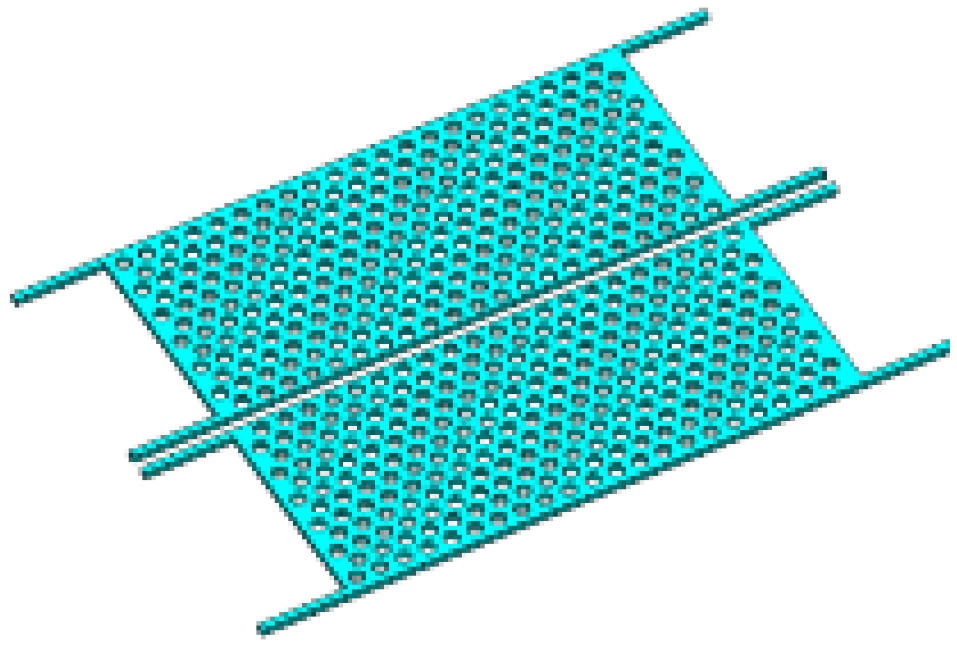 | 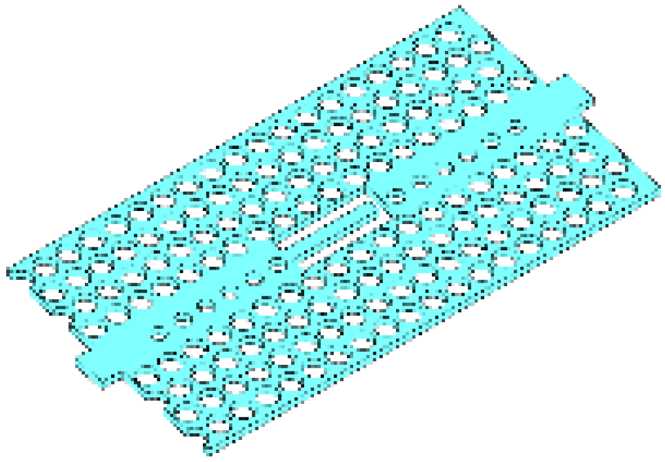 | 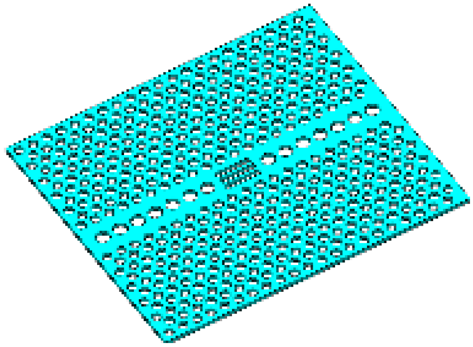 | 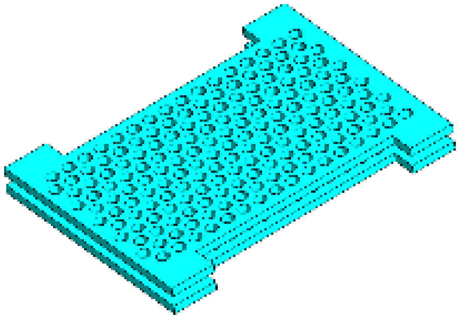 |
| Optical Q | ~104 | >106 | ~371 | 5.3 × 10⁴ | 1.6 × 10³ |
| Mechanical Q | 890 | 50–100 | N/A | >104 | ~2 (air) |
| Mechanical frequency () | 9.54 MHz | ~3 MHz | N/A | >600 MHz | 1.8 MHz |
| Optomechanical coupling rate | 0.23 kHz (g/2π) | 152 GHz/nm | N/A | >200 kHz (g/2π) | N/A |
| Mode volume | ~3 ()3 | N/A | N/A | ~0.021 ()3 | N/A |
| Reference | [81] | [82] | [74] | [83] | [80] |
| PhC Cavity | Principle | Tunable Movement | Factor | Remarks | Sensing Applications | |
|---|---|---|---|---|---|---|
| Single PhC | PCN | Probe perturbation | In-plane translating | * and | Small wavelength tuning range; Moderate optical loss | Displacement [8,42]; |
| 2D PhC Slab | Probe perturbation | Vertical translating | λ | Large wavelength tuning range small optical loss | Displacement [89]; Force [100] | |
| Deformable cavity | In-plane translating | λ | Large wavelength tuning range | Displacement [9]; Magnetic field [13] | ||
| Deformable cavity | N/A | λ | Small wavelength tuning range | Strain [11,98,99]; Electric field [15] | ||
| Cantilever-PhC slab | Deformable cavity | Out-of-plane bending | λ and Q | Large optical loss | Stress [77] | |
| Coupled PhCs | Coupled PCN | Mode splitting | In-plane translating Out-of-plane rotating/bending | λ | Moderate wavelength tuning range; High operation speed and resolution | Magnetic field [14]; Force [54] |
| Vertically Coupled PhC | Mode splitting | Vertical translating | λ and Q | Large wavelength tuning range with high Q-factor; High sensitivity | Stress [12]; Displacement [10]; | |
| Split PCN | Longitudinally split | Deformable cavity | In-plane translating Out-of-plane bending | λ and Q | Large Q-factor tuning range | Displacement [65,66,67,68,69] |
| Transversely split | Deformable cavity | In-plane translating | λ and Q | Wide tuning wavelength range | Rotation and displacement [96] | |
| Types of Accelerator | Device Size | Bandwidth | Sensitivity | Reference |
|---|---|---|---|---|
| MEMS | Large (mm-scale) | 3.2–20 kHz | ~1 mg/Hz1/2 | [139,140] |
| Fiber optics | Small (µm-scale) | 1 kHz | 0.1 µg/Hz1/2 | [141] |
| Optomechanics | Ultrasmall (nm-scale) | >10 kHz | 1–100 ng/Hz1/2 | [130,142] |
| Cavity Type | Material (Opt + Mech) a | Experiment Condition | Sensing Application | |||||
|---|---|---|---|---|---|---|---|---|
| Vacuum (Y/N) | Coupling Scheme | |||||||
| PCN | Si + Si b | N | Tapered fiber | * | 4.4 × | 2900 | 3.8 × | RI [109] |
| Coupled PCN | SiN + SiN c | Y | Tapered fiber | 9500 | Acceleration [130] | |||
| PhC zipper | SiN + SiN | N | Tapered fiber | 4.3 × | 50~150 | 3 × | Motion [45] | |
| Split PCN | Si + Si | N | Tapered fiber | 1.0 × | <100 | 5000 | Magnetometry [70] | |
| Beam embedded 2D PhC | Si + Si | Y | Grating coupler | 2.5 × | 6.3 × | 1230 | 2 × | Mass [86] |
| Air-slot 2D PhC | Si + Si | Y | Tapered fiber | 2 × | 1500 * | 1.2 × | Displacement [85] | |
© 2020 by the authors. Licensee MDPI, Basel, Switzerland. This article is an open access article distributed under the terms and conditions of the Creative Commons Attribution (CC BY) license (http://creativecommons.org/licenses/by/4.0/).
Share and Cite
Xia, J.; Qiao, Q.; Zhou, G.; Chau, F.S.; Zhou, G. Opto-Mechanical Photonic Crystal Cavities for Sensing Application. Appl. Sci. 2020, 10, 7080. https://doi.org/10.3390/app10207080
Xia J, Qiao Q, Zhou G, Chau FS, Zhou G. Opto-Mechanical Photonic Crystal Cavities for Sensing Application. Applied Sciences. 2020; 10(20):7080. https://doi.org/10.3390/app10207080
Chicago/Turabian StyleXia, Ji, Qifeng Qiao, Guangcan Zhou, Fook Siong Chau, and Guangya Zhou. 2020. "Opto-Mechanical Photonic Crystal Cavities for Sensing Application" Applied Sciences 10, no. 20: 7080. https://doi.org/10.3390/app10207080