Abstract
Intelligent light weight concepts are increasingly designed as multi-material systems in order to achieve optimized properties through a targeted combination of materials. For these applications, the market demands joining technologies that make it possible to join foreign materials reliably (e.g., incompatible thermoplastics, thermoplastic-metal and thermoplastic-thermoset). In view of these industrial challenges, thermoplastic staking is an established forming process. At present, computer-aided development and precise FE-simulation (finite element-simulation) of these processes are not state-of-the-art. Accordingly, the previous design is based on subjective empirical values and empirical tests of the component. Within the framework of the paper, these gaps are to be closed by the development of numerical models for the heating and forming behavior of thermal plastic rivets (hot air staking) and the associated experimental validation. This requires the experimental development of the cause-effect relationships between melt formation and the resulting forming behavior. Finally, the numerical simulation shows a high conformity to the experimental data and allows an evaluation of the minimum heating time as well as initial approaches to evaluating the resulting structures by the simulation.
1. Introduction
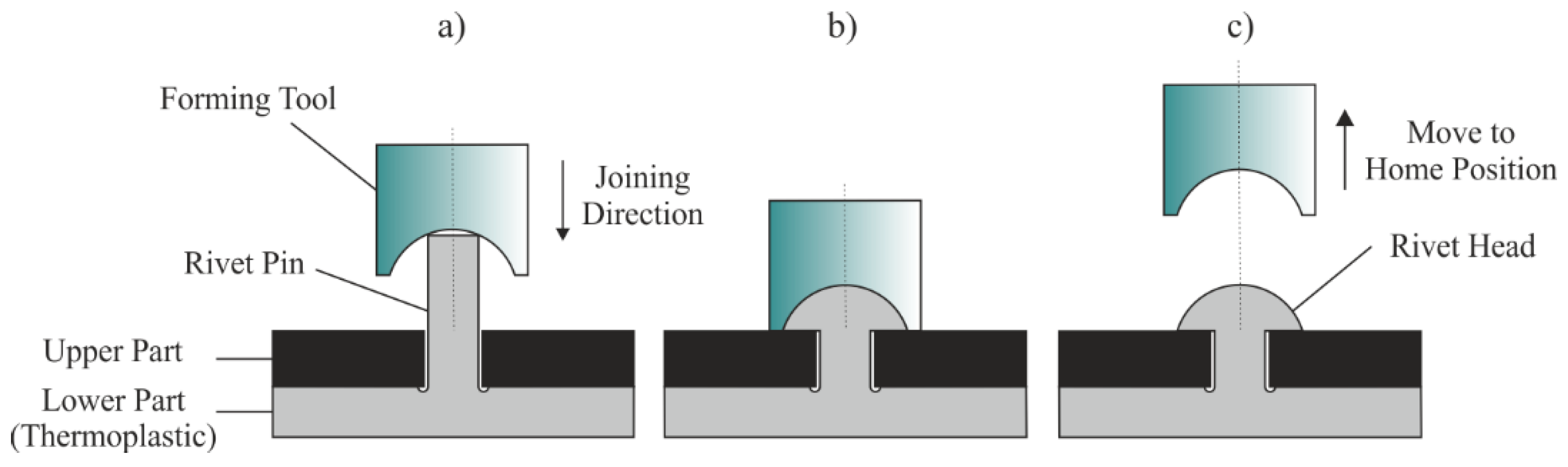
Due to the optimized material adaption by using multi-material-structures, the final part properties can reach maximized performance and efficiency. This fact correlates with the substitution of conventional metal applications by their plastic counterparts and is associated with the increasing demand for joining methods which enable the reliable linking of incompatible materials as well. Based on its cost-efficient processing and typically low cycle time, plastic staking is one of the most commonly used joining processes in this field. It enables the reliable joining of two or more mating parts by having a form-locked and partly force-locked connection. As chronologically shown in Figure 1, the staking process is characterized by forming an added assembly component, which is called a rivet pin. Usually, the pin is constructively associated with the thermoplastic part. The forming of the rivet pin and the subsequent formation of the rivet head lead to an undetachable undercut [1].
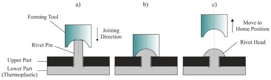
Figure 1.
Main principle of a staking process, (a) before staking, (b) end position of the forming tool, (c) return of the forming tool after staking.
In literature the commonly used staking processes are classified in dependence on their heat transfer mechanism. Consequently, they have to be differentiated in heat conduction (hot forming), convection (hot air staking), intermolecular friction (ultrasonic staking), and radiation (infrared and laser staking). The fundamental forming process is basically equivalent for all staking processes and thus independent of the type of energy input. However, as shown in Figure 1, the forming tool forms the rivet pin down to the top of the upper part. The characteristic geometry of the rivet head is incorporated into the forming tool. By using single stage processes, such as hot forming, the heating and forming take place simultaneously. In a double-stage process, such as hot air staking, the shaping happens only after the sufficient plasticization of the rivet pin.
In contrast to the increasing number of staking applications, regarding the dimensioning of rivet joints there is no uniform designing tool available. Consequently, the optimization of process and design is mainly based on empirical tests and expert knowledge. Nevertheless, the German guideline DVS 2216-3 [2] provides some information about preferred rivet geometries. All design recommendations in the guideline are based on the diameter of the rivet pin and the volume of the rivet head. Finally, the length of the rivet pin is a calculated parameter to reach an adapted volume of the rivet head and pin. However, the focus of the guideline is primary on the ultrasonic staking, and it summarizes the experience of industry. Detailed information regarding further rivet processes as well as reachable joint properties or emerging weld lines are not included.
In respect to the relationships between process, structure, and joint properties, it has to be pointed out that the research project [3] has already investigated the relevant influencing parameters regarding a load-bearing as well as design-compatible rivet geometry for different rivet processes. Additionally, the reachable joint properties were analyzed for different kinds of plastic as well as with and without fillers. The results show that the joint properties depend on the heat transfer mechanism and the plastic material, as well as the quality of the connection area between rivet head and rivet pin. Especially for single-stage staking processes, critical defects could be detected in the connection area which lead to a weakening of the joint strength. Furthermore, the research project pointed out that the surface of the rivet head does not correlate with the internal materials structure and the joint properties. However, the research project [3] did not clearly provide close examinations of the process-dependent heating and forming behavior and its effects on the resulting material structure (e.g., crystallinity) [3,4]. Consequently, to obtain a comprehensive understanding of the interactions between heating and forming, a numerical process simulation is used in the present paper.
The basic challenge in the numerical simulation of a staking process is the change of the plastic material from solid to molten state and back during staking. Additionally, the thermal condition has a primary influence on the resulting material structure and must be considered with sufficient accuracy. Thus, the simulation model has to consider the elastic-plastic material behavior in the solid state as well as the viscous flow behavior of the plastic melt. Regarding the numerical analysis of the manufacturing process, in which solids interact with fluids, various calculation approaches exist. On the one hand, polymer injection forming (PIF) was simulated in [5] by means of a coupled fluid structure calculation. In this case, the sheet metal was linked with the plastic part, by using the Euler-formulation and Lagrange´s description. Regarding the simulation of the staking process, this approach could not apply, because of the continuously changing material state during forming. On the other hand, processes, in which solids interact with fluids, were calculated with pure structure code. In [6] and [7] the viscous flow behavior of adhesives during a clinching process was simulated in numerical simulation by using the rate-power-law. Nevertheless, even with this process simulation, the definition of the melt range was carried out in advance. Additionally, the literature provides some information about the numerical simulation of infrared staking [8,9]. In this regard, the viscous flow behavior of the plastic melt was neglected. Furthermore, the elastic-plastic material behavior was only considered in the temperature range of 25 °C to 100 °C.
In summary, the current literature confirms that the numerical process simulation, in which solids interact with fluids, is basically possible. Nevertheless, the current work has the limitation to assign the local material state (viscous or elastic-plastic material behavior) in advance. The current literature also shows, that the numerical simulation of staking processes investigates in fact the heating and cooling behavior in the influence to the tensile strength [8,9]. Nevertheless, all simulations were carried out without the consideration of the viscous material behavior of the melt. Beyond that, no work is known on process simulation which provides information about macroscopic errors, such as weld lines or cavities due to shrinkage.
However, based on the state of the art, the following scientific approach can be defined. In comparison between simulation and experiment, the influence of design, material, and process should be analyzed regarding the double-stage process hot air staking. In this regard, the heating and forming behavior for this process should be investigated. The aim is to create a simulation model, based on experimental data, close to reality, to predict the melt formation during heating as well as the materials structure after forming. The simulation should give some information about the minimal heating time of the rivet pin to form the rivet head and should predict the potentially weak points of the joint. Additionally, the numerical simulation should already increase the process transparency for future investigations in regard to the linking between the joint properties and the physical values, such as materials stress and strain.
2. Materials and Methods
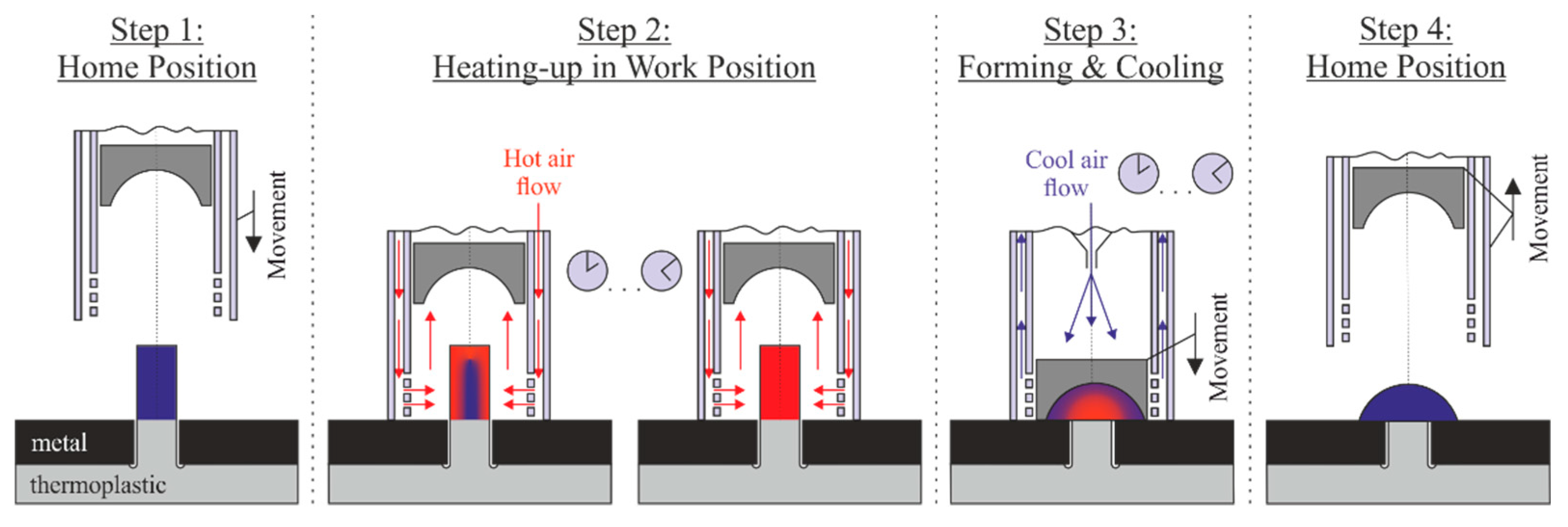
For the experimental investigations a hot air staking machine of the company bdtronic GmbH (Weikersheim, Germany) (type B2000-H) was used. Figure 2 shows the schematic illustration of the hot air staking process, consisting of four process steps. In step 1 the mating parts are inserted in the part mounting and the hot air pipe moves to its work position. In the work position the hot air pipe surrounds the rivet pin. In the following step 2 the hot air flows in the wall of the hollow cylinder down to the bottom, leaves the wall and flows upward in the middle of the hot air pipe. This fact leads to a heating of the rivet pin. After a sufficient heating time, the coaxial mounted forming tool forms the rivet heat by moving to the top of the upper mating part. Subsequently, the cooling starts by haven a cool air flow to the top of the forming tool (step 3). In step 4 the forming tool as well as the hot air pipe move back to their home position.
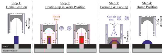
Figure 2.
Schematic illustration of the hot air staking process consisting of four process steps.
The plastic material for all investigations was polypropylene (PP), type Moplen HP501 H (manufacturer LyondellBasell, Rotterdam, the Netherlands), which has excellent properties for structural analysis by microscopy to investigate the heating and forming behavior. The rivet pin has a diameter of 3.0 mm and a length of 10.8 mm. By using an upper mating part of steel X5CrNi18-10 (1.4301) its properties are not changed by the staking process. The thickness of the mating part is 3.0 mm, which leads to a constant protruding length of the rivet pin of 7.8 mm. The rivet head had the common industrial design of a hemisphere with a diameter of 6.0 mm, and was adapted to the protruding volume of the rivet pin. In addition, the following (optimized) process parameters were used for the experimental analysis:
- Air temperature TA = 300 °C
- Air flow rate QA = 75 L/min
- Variation of the heating time tE = 1 s/2 s/3 s/5 s/8 s
- Joining force FJ = 80 N
- Cooling time tC = 12 s
To investigate the heating and forming behavior, transmitted-light microscopy was used. Therefore, the rivet pin and rivet joint were prepared as an extracted thin cut (thickness 10 µm) in the center plane of the rivet pin. By using a polarization microscope (Olympus BX51, Olympus Corporation, Shinjuku City, Tokyo, Japan), the melted and recrystallized area was measured (software Imagej, National Institutes of Health, Bethesda, Rockville, MD, USA) and characterized the melt formation during heating, and the materials structure after forming, respectively. In addition, the necessary thermal material parameters for thermal capacity were determined experimentally. To determine the temperature-dependent thermal capacity, DSC (differential scanning calorimetry) measurements were carried out in accordance with DIN EN ISO 11357-1 with a dynamic heat flow differential calorimeter of type Q2000 (TA Instruments, New Castle, PA, USA) in the temperature range from 10 to 320 °C. The temperature-dependent thermal conductivity was taken from the Moldex 3D (CoreTech System Co., Taiyuan St. Zhubei City, Taiwan) software material database.
Furthermore, a numerical process simulation was used to increase process transparency. Therefore the software simufact.forming, (simufact engineering gmbh, part of Hexagon’s Manufacturing Intelligence division, Hamburg, Germany), was used. With the help of the simulation, the material flow during staking was observed, depending on different heating times.
3. Results and Discussion
3.1. Experimental Study to the Heating and Forming Behavior by Using the Hot Air Staking Process
Figure 3 shows the time-dependent melt formation during heating for a heating time tE between 0 s and 8 s. The melt formation starts at the outside and continues towards the middle of the rivet pin. One advantage of PP as a material is that the plasticized and recrystallized areas are very well recognizable by the deviating materials structure in comparison to the structure after injection molding. While at short heating times a non-plasticized area remains in the middle of the rivet pin, an almost complete melting of the protruding rivet pin can be observed from a heating time tE of 8 s. As shown in Figure 4, the increase of the generated melt layer as a function of the heating time shows an almost linear or slightly progressive course, which indicates an even energy input during hot air heating.
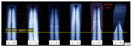
Figure 3.
Melt formation shown by thin sections of the rivet pin for different heating times (transmitted-light microscopy). Process parameters: material polypropylene (PP), diameter rivet pin dP = 3.0 mm, air temperature TA = 300 °C, air flow rate QA = 75 L/min.

Figure 4.
Melt formation characterized by the molten area AMelt as a function of the heating time tE, the molten area is associated with Figure 3.
However, based on the microscopic analyses in Figure 3, a higher thickness of the melt layer could be detected on the upper side of the rivet pin than on its outside. The reason for this effect is assumed to be the area-dependent flow behavior of the hot air, the associated specific heat transfers into the material, and the heat accumulation during gas dissipation, which forms on the forming tool located in the hot air pipe. The systematic consideration of these effects is a current concern in the present project.
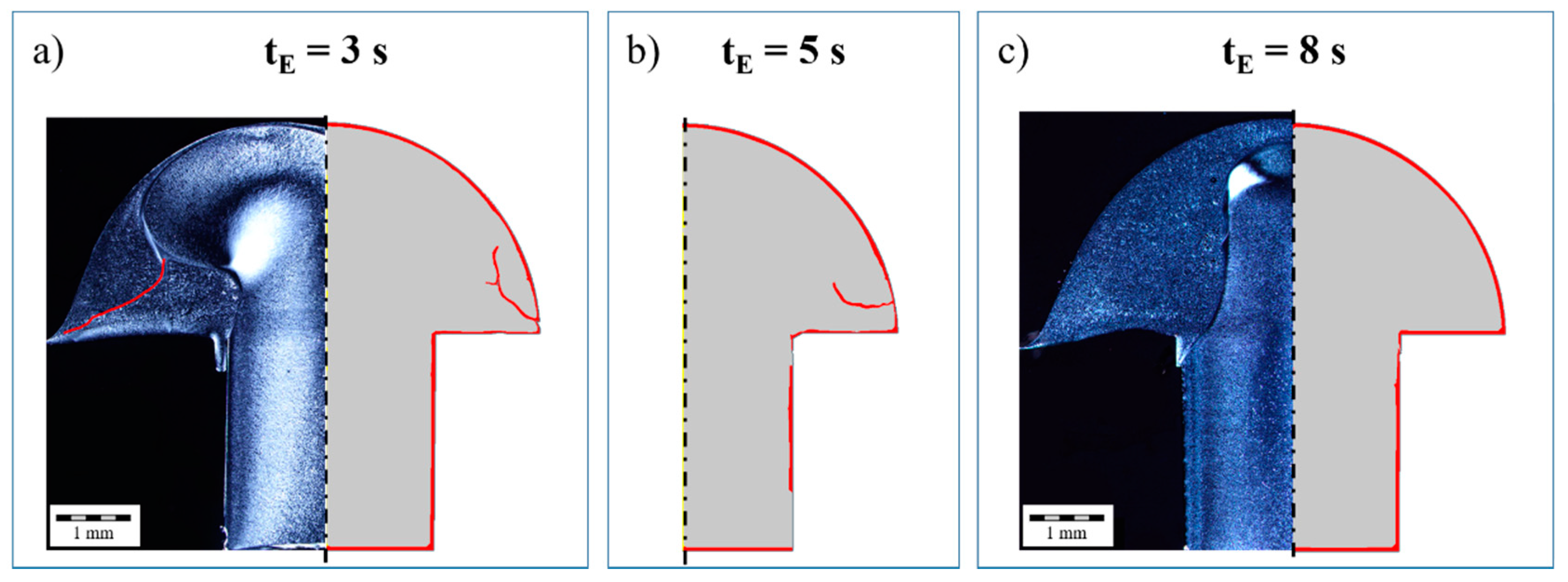
The experimental investigations pointed out that the minimal heating time tE depends primarily on the air temperature TA and the air flow rate QA [10]. Simultaneously, there is a significant dependence on the selected joining force FJ. In this context, Figure 5 shows the comparison of the melt formation as well as the formed joint for two significant different heating times tE. A heating time tE of 3 s present a clearly deviant melt volume in comparison to the volume of the protruding rivet pin (see Figure 5a). Nevertheless, a complete forming of the rivet pin is still possible. However, a high percentage of cold forming must take place during the forming process. At the end, the joint shows four different main structural zones in the rivet head. On the one hand, there are areas (I) made of plasticized, formed, and subsequently recrystallized material, which are mainly located in the side areas of the rivet head. On the other hand, areas (II) could be detected which still have their material structure, induced by the injection molding process, and were thus subject to predominantly cold forming. Consequently, it is expected that these areas will have an increased stress state. The areas (II) extend into the lateral areas of the rivet head and lead to a structurally uneven formation of the joint. Nevertheless, no open connection or defect could be detected during the hot air staking process. Between the areas (I) and (II) there are areas (III) with increased shear stress during forming. The melt shears are generated at the structural border of the solid material during forming because of the materials flow. Finally, area (IV) shows an undefinable weld line in the rivet head. The cause of the weld line cannot be finally clarified on the basis of the experimental data. Therefore, the evolution of the individual zones during the process is subsequently analyzed with the aid of numerical process simulation.
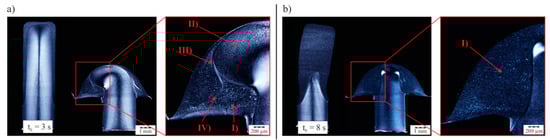
Figure 5.
Heating and forming behavior characterized by the materials structure in the rivet pin and the rivet head, illustrated in (a) by the comparison of a short heating time (tE = 3 s) and in (b) by a long heating time (tE = 8 s)—(I) melted and recrystallized structural zone, (II) cold formed structural zone, (III) shear zone during forming between melted and non-melted material, (IV) weld line. Process parameters: material PP, diameter rivet pin dP = 3.0 mm, air temperature TA = 300 °C, air flow rate QA = 75 L/min, heating time tE = 3 s/8 s, joining force FJ = 80 N, cooling time tC = 12 s.
In contrast to a short heating time, Figure 5b shows the melt formation and the joint for a heating time tE of 8 s. Due to the longer heating time, the melt layer is clearly thicker. Consequently, the forming of the rivet pin leads to a predominantly uniform material structure in the rivet head. Especially in the connection area of the rivet head and the rivet pin, entirely plasticized and subsequently recrystallized material could be detected. Furthermore, the materials structure is quite homogeneous and the dominance of the shear zone between melted and solid material areas is much less significant. In comparison to the heating time tE of 3 s, there is no detectable weld line in the rivet head.
3.2. Numerical Analysis of the Heating Behavior in Comparison to the Experimental Data for Hot Air Staking
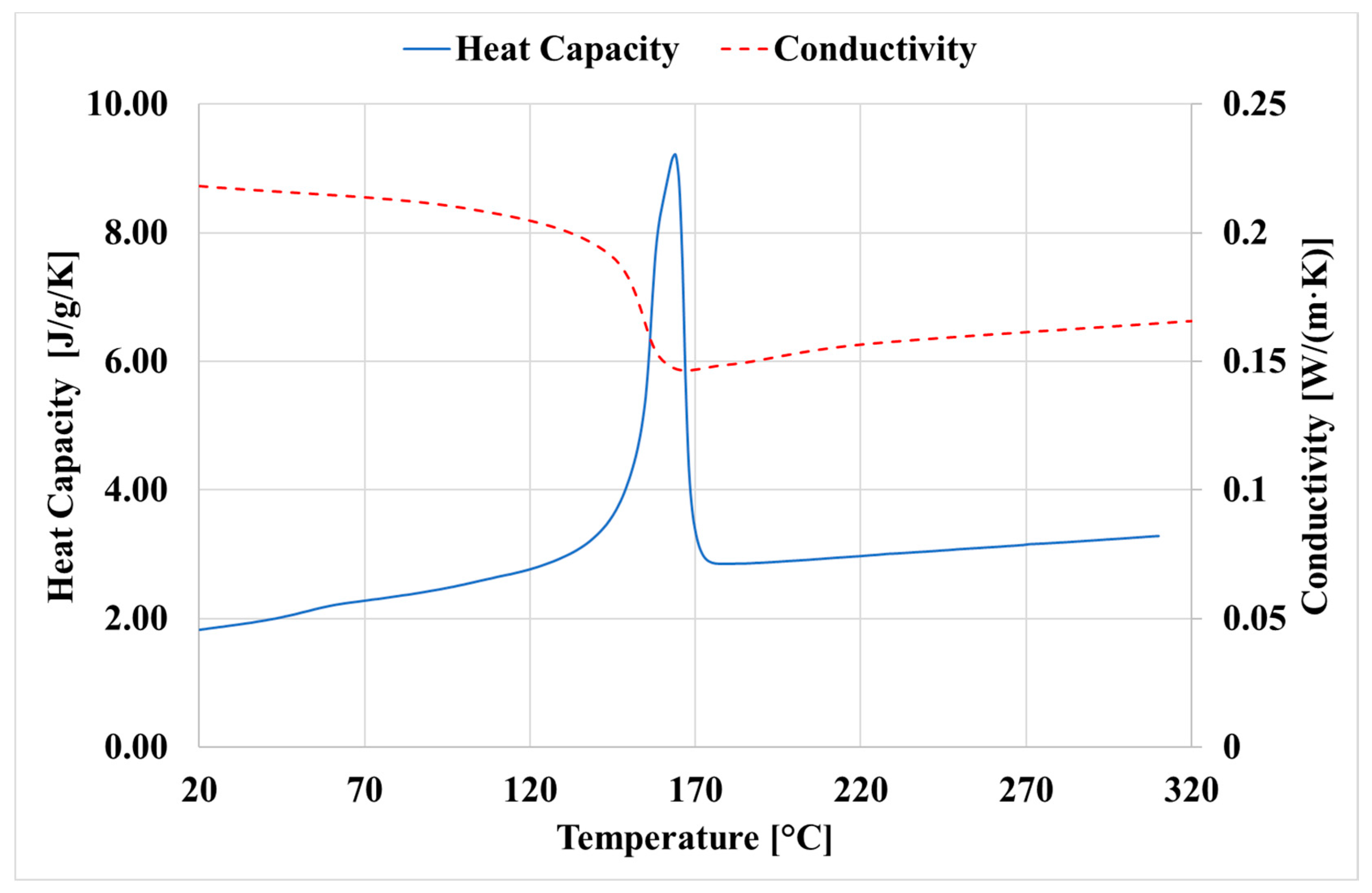
In a first step, the heating process was simulated with the software simufact.forming by a 2D-rotationally symmetric thermomechanical process simulation. In order to calculate the temperature distribution within the workpiece, the Fourier heat conduction equation was used to calculate the heat conduction processes in the workpiece. The necessary thermophysical parameters heat capacity and heat conduction were determined experimentally as a function of temperature and implemented in the simulation system in tabular form. Figure 6 shows the heat capacity and thermal conductivity as a function of temperature.
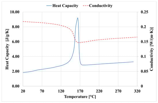
Figure 6.
Measured heat capacity and conductivity depending on the temperature.
The heating of the rivet pin by the hot air is achieved by a heat transfer at the contact surfaces. In the simulation, a heat transfer coefficient must be defined for this purpose, with which the heating behavior can be realistically represented. The heat transfer coefficient was determined iteratively by comparing the heating behavior on the basis of the thin sections.
Regarding the heat flow of the hot streaming air, the heat transfer coefficient to the environment was set to 2000 W/(m² K). Thus the component heats up homogeneously from the outside to the inside. On the basis of the thin sections (cf. Figure 3, however, it could be shown that the heating is stronger in the area of the front surface. The reason for this is assumed to be the accumulation of hot air under the forming punch. In order to be able to take this into account numerically, a heating plate was inserted into the model, which simulated the heating caused by the hot air at rest under the punch. Figure 7a shows the simulation setup and Figure 7b a comparison between experiment and simulation. It can be seen that the numerical assumptions made allow the melt formation (red areas) to be simulated realistically in terms of quality and quantity. The calculated temperature distribution is the initial condition at the beginning of the riveting process.
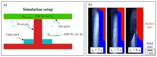
Figure 7.
(a) Simulation setup for the calculation of the heating process and (b) comparison of the experimental and simulation data for different heating times tE.
3.3. Numerical Analysis of the Forming Behavior in Comparison to the Experimental Data for Hot Air Riveting
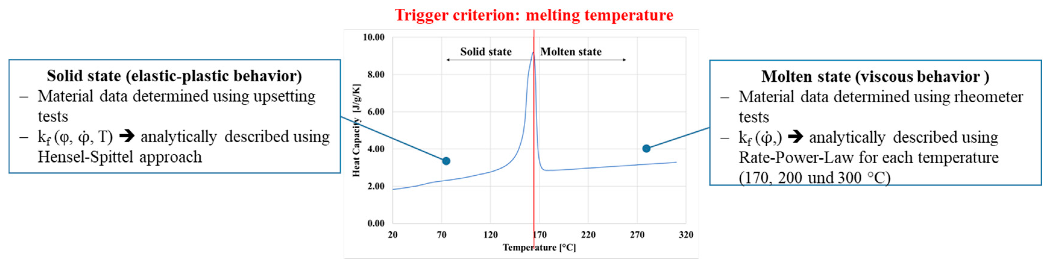
The numerical simulation of hot air riveting is very challenging because the plastic material is present in the workpiece in both the solid aggregate state and the molten state. In order to be able to reproduce this numerically, a subroutine was developed with which a distinction can be made between the viscous and elastic-plastic material behavior. The element temperature serves as trigger criterion. If this is above the temperature of the melting temperature range of the plastic, the viscous temperature-dependent material behavior is assigned to the corresponding element. Otherwise the elastic-plastic material behavior is used. The conceptual approach of the subroutine for case distinction and material assignment is shown in Figure 8.
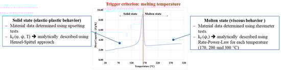
Figure 8.
Basic concept of the subroutine for case distinction and material assignment.
In order to describe the material behavior for the elastic-plastic state, the yield stress is described according to the Hensel–Spittel approach see Equation (1).
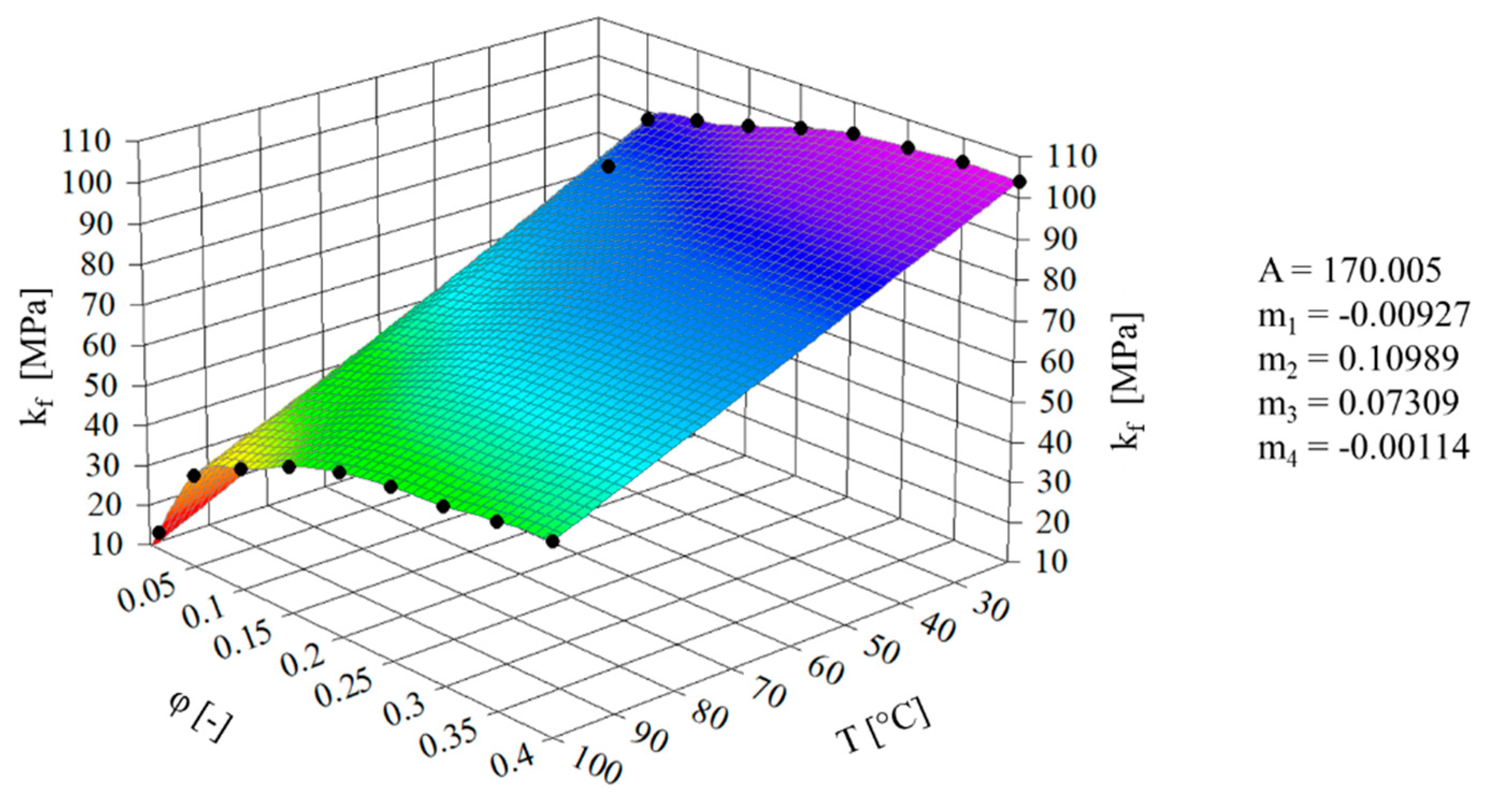
Using this phenomenological approach, the yield stress is described as a function of the plastic strain, the strain rate, and the forming temperature. The flow curves were determined by cylinder upsetting test and on the basis of these the parameters of the Hensel–Spittel approach could be determined. Figure 9 shows the calculated yield stress kf according to Equation (1) as a function of the plastic strain and the temperature at a strain rate of 0.1 s−1 and the determined parameters. A detailed description of how to carry out the cylinder upsetting tests and determine the flow curves is given in [11].

Figure 9.
Flow stress depending on plastic strain and temperature for the material PP in the solid state.
Furthermore, the flow behavior of the molten plastic must be described within the process simulation for the Lagrange approach. In this paper this is done with the so called Ostwald–de Waele power law model in the form
(with shear stress and shear rate ). In this form, however, the equation cannot be used with the subroutine because, similar to the solid state, the yield stress has to be defined as a function of the plastic strain or strain rate. By applying the shape change energy hypothesis or the comparative forming rate according to von Mises Equation (2) can be reformulated according to [6]:
By means of rheometer experiments, the complex viscosity as a function of shear rate can be determined experimentally for different temperatures. The forming speed can be calculated directly from the shear rate according to Equation (4):
From the mathematical relationships shown, the yield stress for each temperature can now be approximated according to Equation (5):
This equation is defined within the FE-tool simufact.forming, and by applying the method of least squares, the coefficients C1 and C2 for Equation (5) can be determined for each test temperature from Equation (3). In [12] the approach for determining the coefficients is explained. Table 1 shows the determined coefficients for the corresponding testing temperature.

Table 1.
Determined coefficients for the corresponding testing temperature.
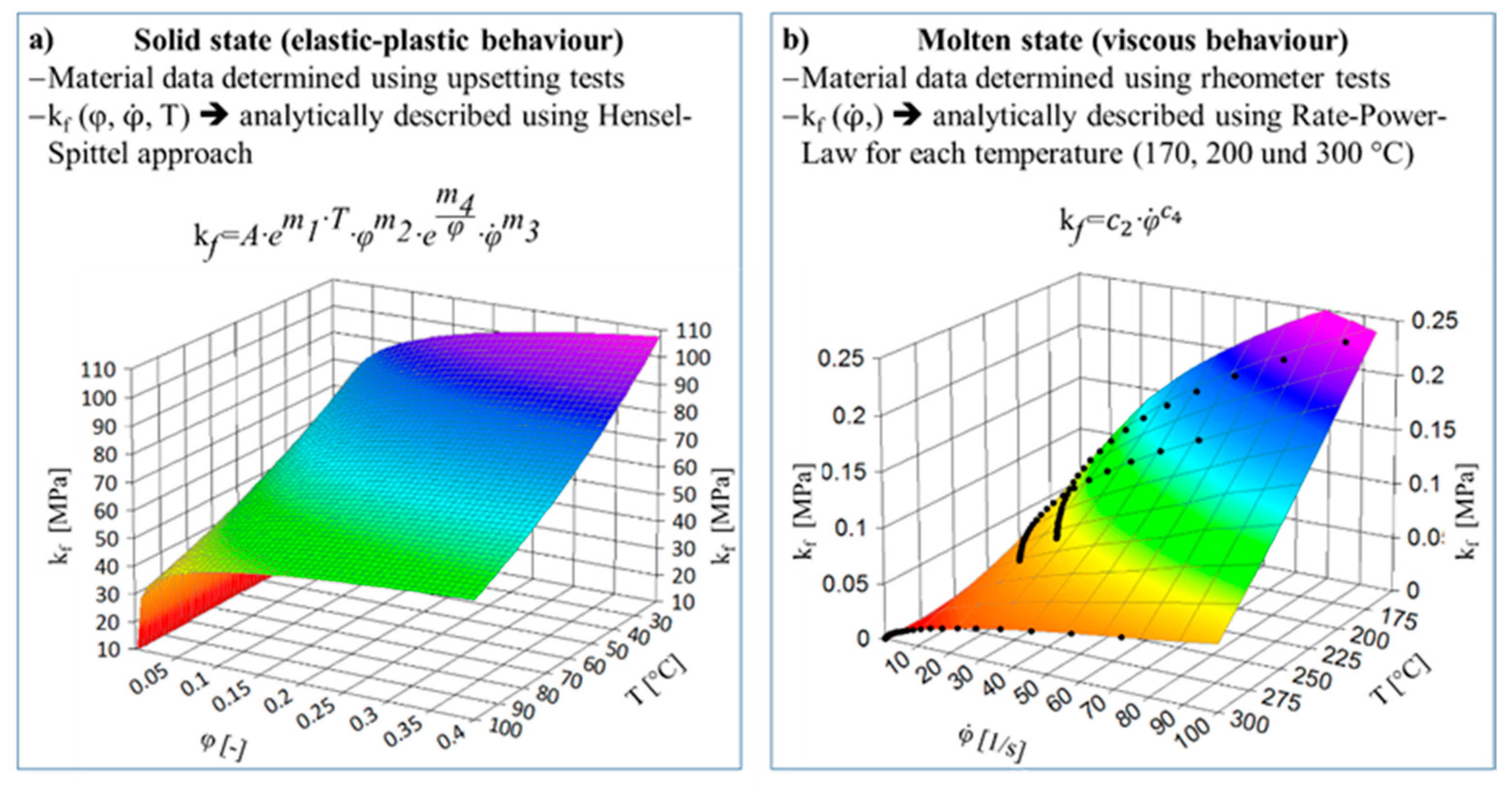
Figure 10 summarizes the experiments for material data determination, the analytical approaches used, and the resulting yield stresses for both solid (a) and the molten state (b). The suitability of material characterization by means of cylindrical upsetting tests for plastics in the solid state for compressive stresses was demonstrated in [11]. Furthermore, the numerical simulation and verification of the behavior of molten adhesive by means of a rate-power-law model was carried out in [12]. The approaches used in this thesis are therefore suitable.
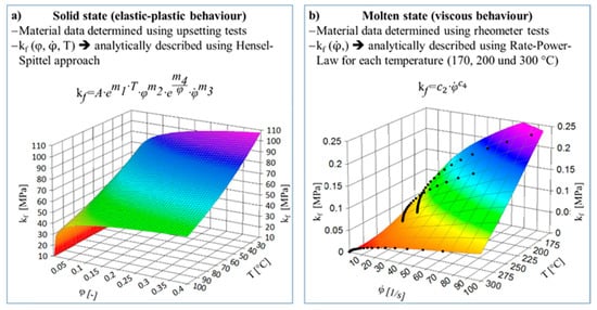
Figure 10.
Characterization of the material properties for the solid (a) and molten state (b).
The necessary thermal material parameters for thermal capacity and the temperature-dependent thermal conductivity shown in Figure 6 were also implemented.
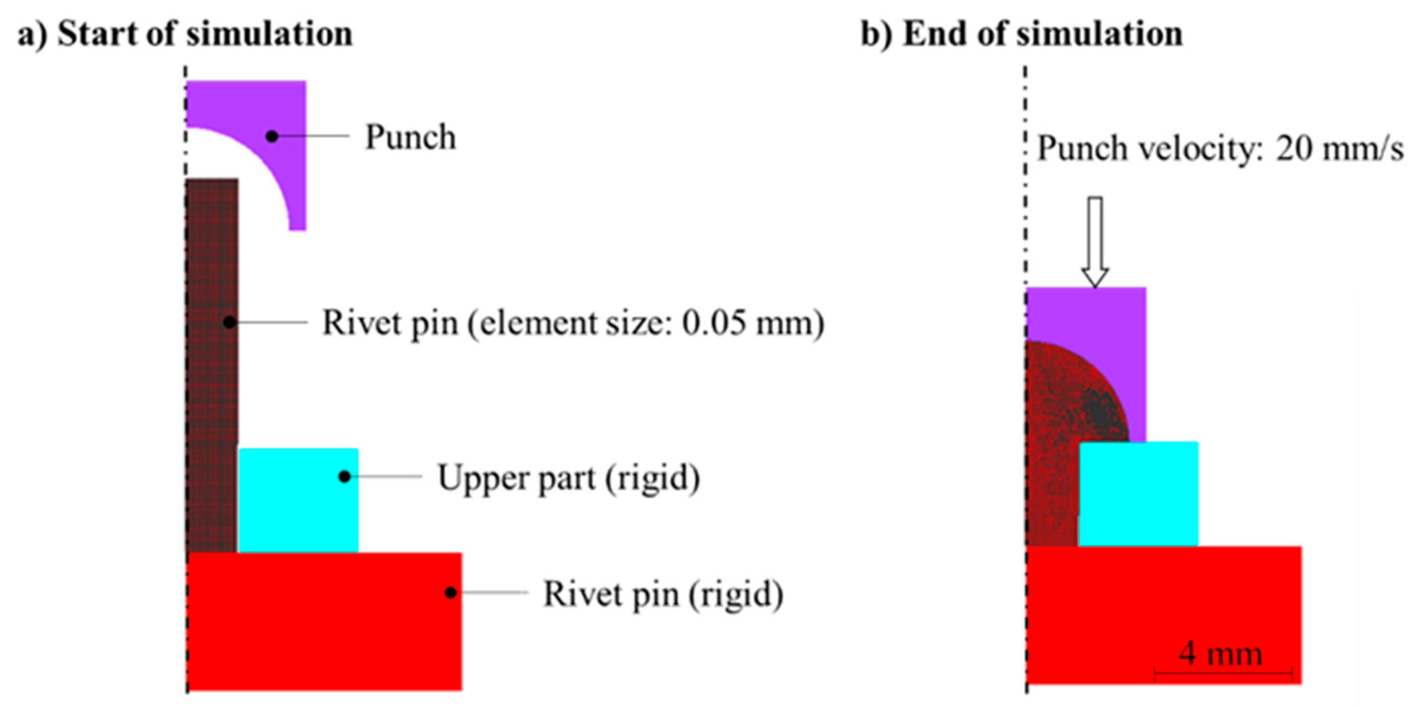
The process simulation was carried out with a 2D rotationally symmetrical model using the real tool geometry. The punch speed was assumed to be constant (vPunch = 21.25 mm/s) and was determined experimentally by measuring the process duration. To be able to reproduce the material flow as realistically as possible, the rivet pin was meshed very finely with an element edge length of 0.05 mm (quad elements). Furthermore, the combined friction model with µ = 0.1 and m = 0.5 was used to calculate the friction shear stress. A detailed description of the combined friction model is given in [12]. Figure 11 shows the basic simulation setup at the beginning (a) and at the end of the process (b).
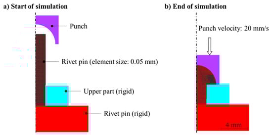
Figure 11.
Basic simulation setup at the beginning (a) and at the end of the process (b).
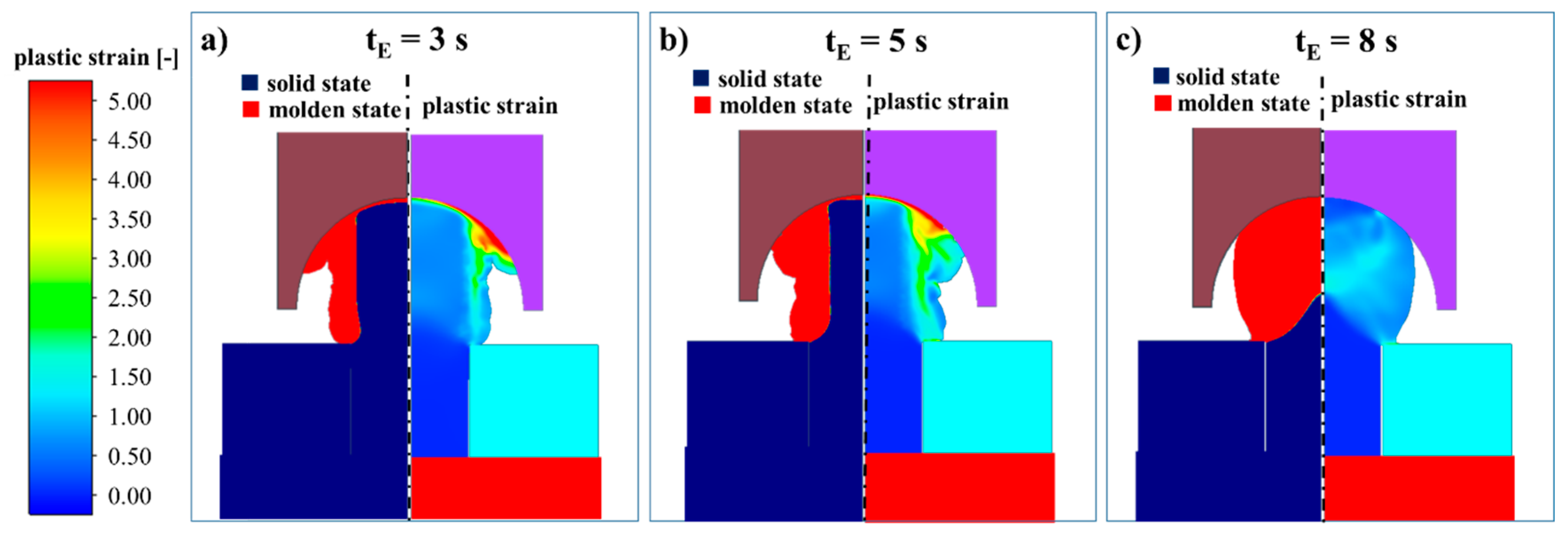
With the help of the numerical process simulation of hot air staking, the influence of the heating time on the forming behavior and the resulting materials structure was analyzed. Figure 12 shows the material distribution at 80% of the joining path for the heating times tE of 3 s, 5 s, and 8 s. The left section of the picture shows which area of the plastic is in molten or solid state and the right section shows the resulting distribution of the plastic strain. With a heating time of 3 s, the rivet pin to be formed is only partially in the molten state. As a result of the forming process, the molten area is primarily formed, as this area has a significantly lower strength. For this reason, the rivet pin is not formed homogeneously as shown in Figure 12a. The distribution of the plastic strain is also strongly inhomogeneous at a heating time of 3 s. The largest forming takes place in the molten area of the plastic, due to the significantly lower strength. With an increase in the heating time, the molten plastic fraction increases and the strength gradient is reduced, so that with a heating time of 8 s an almost homogeneous forming of the rivet pin takes place. Figure 12c shows that the rivet pin bulges out homogeneously and a homogeneous distribution of plastic strain continues to occur. Nevertheless, a complete cavity filling is achieved at every heating temperature. In the following, an analysis is done to determine how the quality of the rivet pin may be affected.
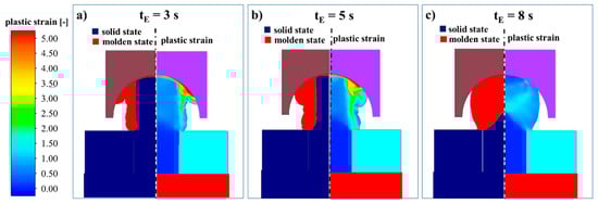
Figure 12.
Numerical analysis of the mold filling behavior characterized by the plastic strain as well as the molten and solid material areas for a joining path of 80% and different heating times tE of (a) 3 s, (b) 5 s and (c) 8 s.
The contact is analyzed within the numerical simulation to evaluate the formed rivet head quality. If the material contacts itself as a result of the forming process, an emerging weld line is formed. In the worst case, the material contacts itself at too low temperatures and pressures, so that no welding takes place and therefore no material bond prevails in the areas. Figure 13 shows in detail the material flow at a heating time of 3 s as a function of the punch stroke. It can be seen that the self-contact occurs for the first time already at a punch stroke of 3.95 mm. The zone or length of the emerging weld line increases steadily until the end of the process.
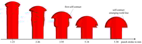
Figure 13.
Material flow during hot air staking with a heating time tE of 3 s for three-quarter model of the rivet pin.
The analysis of the self-contact areas at the end of the process shows that the orientation/direction of the emerging weld lines as well as the length changes with increasing heating time tE (Figure 14). From a heating time of 8 s, the rivet head is formed in such a way that no self-contact occurs and thus no emerging weld lines are caused. Figure 10 also shows that the quantitative numerical prediction of the occurrence of emerging weld lines is realistic, as the comparison with thin sections shown.
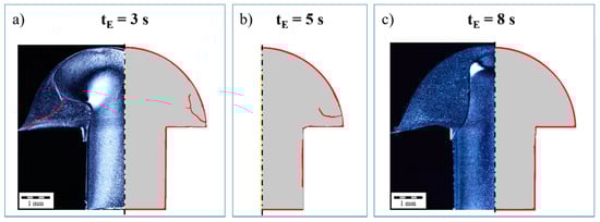
Figure 14.
Numerical analysis—illustration of the emerging weld lines due to self-contact of melted areas during forming for different heating times tE as well as the comparison between numerical and experimental data, (a) tE = 3 s, (b) tE = 5 s, (c) tE = 8 s.
It can be noted that optimum rivet head forming is achieved with a minimum heating time of 8 s. If the heating time is reduced, the fraction of molten plastic at the time of forming is too low and emerging weld lines are formed as a result of self-contact. This is shown in the same way by experiment and simulation. However, the mechanisms of emerging weld line formation could only be understood holistically with the help of numerical process simulation.
4. Conclusions
Within the scope of the present paper, the heating and the forming behavior of the hot air staking process has been numerically simulated by executing a comparison between simulation and experiment. In this regard, the numerical simulation shows a high qualitative conformity to the experimental data. Thus, the molten material portion, depending on the heating time, can even be quantitatively well represented numerically during the simulation of the heating process. Furthermore, the process simulation of hot air riveting allows a realistic calculation of the formation and position of any emerging weld lines. In contrast to the current literature [8,9], the present simulation also considers the viscous material behavior of the melt during the staking process which ensures a much more realistic process model.
As shown, the heating time has a primary influence on the generated melt layer as well as the materials structure after forming. A short heating time leads to an inhomogeneous structure in the rivet head and the formation of emerging weld lines. By increasing the heating time, the material structure as well as the position and geometry of the emerging weld line could be influenced directly. Consequently, for the evaluation of the heating time, there has to be a differentiation between a minimal heating time to have a complete forming and a heating time to have a homogeneous structure in the rivet head without emerging weld lines. However, the generated weld lines due to self-contact could be representative of the minimal heating time, in regard to quality assurance. Finally, the simulation allows an evaluation of the minimum heating time and provides information about the resulting material structure as well as macroscopic errors (e.g., weld lines or cavities). No comparable research findings currently exist.
However, an outstanding topic is the influence of the different materials structure to the mechanical properties. This is the current topic in the present research project. Furthermore, the simulation should be adapted to single-stage staking processes.
Author Contributions
Conceptualization, S.H. and E.B.; methodology, S.H. and E.B.; investigation, S.H. and E.B.; resources, B.A. and M.G.; writing—original draft preparation, S.H. and E.B.; writing—review and editing, B.A. and M.G.; supervision, B.A. and M.G.; All authors have read and agreed to the published version of the manuscript.
Funding
This research was funded by the German Research Foundation, grant number 413515815. The publication of this article was funded by Chemnitz University of Technology.
Conflicts of Interest
The authors declare no conflict of interest.
References
- Ehrenstein, G.W. Handbuch Kunststoff-Verbindungstechnik; Carl-Hanser-Verlag: München, Germany, 2004. [Google Scholar]
- DVS 2216-3. Taschenbuch DVS-Merkblätter und Richtlinien—Fügen von Kunststoffen; DVS-Verlag GmbH: Düsseldorf, Germany, 2010. [Google Scholar]
- Final Report IGF Project. Konstruktions—und Prozessoptimierung von Kunststoffnietverbindungen; Project number 17.997 BR; Technische Universität Chemnitz-Professur Kunststoffe: Chemnitz, Germany, 2015. [Google Scholar]
- Brückner, E.; Gehde, M.; Jahnke, T.; Kazmirzak, W. Kunststoffnieten—Einflüsse und Restriktionen hinsichtlich Konstruktion und Prozess. Join. Plast. Fügen Kunstst. 2016, 2016, 90–98. [Google Scholar]
- Behrens, B.A.; Bouguecha, A.; Götze, T. Simulation Eines Wirkmedienbasierten Blechumformprozesses; UTFscience, Meisenbach Verlag: Bamberg, Germany, 2010. [Google Scholar]
- Gerstmann, T. Erweiterung der Verfahrensgrenzen des Flach-Clinchens. Ph.D. Thesis, Technische Universität Chemnitz, Chemnitz, Germany, 2016. [Google Scholar]
- Etemadi, S. Entwicklung Einer Praxisnahen Methodik für die Simulation des Clinchklebeprozesses. Ph.D. Thesis, Universität Paderborn, Paderborn, Germany, 2012. [Google Scholar]
- Park, H.S.; Nguyen, T.T. Development of infrared staking process for an automotive part. IOP Conf. Ser. Mater. Sci. Eng. 2015, 95, 12–19. [Google Scholar]
- Park, H.S.; Nguyen, T.T. Development of a new staking process for an automotive part. Int. J. Adv. Manuf. Technol. 2017, 89, 1053–1068. [Google Scholar]
- Brückner, E.; Gehde, M. Analyse des Prozessablaufs beim thermischen Kunststoffnieten am Beispiel von Polypropylen. In Proceedings of the Technomer 2017-25. Fachtagung über Verarbeitung und Anwendung von Polymeren, Chemnitz, Germany, 9−10 November 2017; Gehde, M., Ed.; V6.6. Technische Universität Chemnitz, Institut für Fördertechnik und Kunststoffe: Chemnitz, Germany, 2017. ISBN 978-3-939382-13-3. [Google Scholar]
- Graf, M.; Härtel, S.; Binotsch, C.; Awiszus, B. Forging of Lightweight Hybrid Metallic-Plastic Components. Procedia Eng. 2017, 184, 497–505. [Google Scholar]
- Gerstmann, T.; Awiszus, B. Hybrid joining: Numerical process development of flat-clinch bonding. J. Mater. Process. Technol. 2020, 277, 116421. [Google Scholar]


© 2020 by the authors. Licensee MDPI, Basel, Switzerland. This article is an open access article distributed under the terms and conditions of the Creative Commons Attribution (CC BY) license (http://creativecommons.org/licenses/by/4.0/).