Featured Application
Validation of the methodological accuracy of postoperative methods for locating an implant’s position can help clinicians to select a reliable method and interpret the results of other reports.
Abstract
Assessment of the accuracy of an implant guide system is essential, yet the reliability of postoperative methods for locating the implant position has still not been clarified. This study therefore sought to evaluate the accuracy of postoperative methods for locating the actual position of implants in terms of their linear and angular deviations. The implant position in a dentiform model was located using the following three methods: manual matching on a cone-beam computed tomography (CBCT) image (MC group), manual matching on a mesh model of CBCT (MM group), and automatic matching on a scan abutment of a scan image (AS group). Thirty clinicians adopted each method, and the estimated position of the implant in each group was compared three-dimensionally with the reference implant position using image analysis software in terms of the linear, vertical, and angular deviations. One-way analysis of variance (ANOVA) and Tukey’s post-hoc test were used for statistical analyses (α = 0.05). In general, the deviations were the largest in the MC group, followed by the MM group and the AS group. The ANOVA results suggested that all deviations values were markedly smaller in the AS group than in the MC group (p < 0.001). The interoperator measurement variability of all deviations was relatively smaller in the AS group than in the other two groups. The automatic matching method using scan abutments was more accurate than the manual matching methods using CBCT and mesh images in assessing the deviations that existed between the planned and actual positions of the implant. The use of scan abutments is recommended for the postoperative assessment of an implant’s placement location.
1. Introduction
Critical anatomic structures such as the maxillary sinus, infra-alveolar nerve, and adjacent teeth must be considered while planning the positioning of dental implants before surgery [1]. The accurate placement of implants is essential to minimize periodontal, prosthetic, and esthetic complications [2,3,4]. Incorrect placement can decrease the longevity of implants due to serious complications [5,6]. Surgical guide templates have been traditionally used to transfer the planned position of implants into the oral cavity [7]. Conventional surgical guide systems are designed based on two-dimensional radiographic images and stone casts [8]; however, their fabrication is labor-intensive and incorporates only limited details of the gingiva and underlying bone structures [9]. With the development of medical imaging technologies, cone-beam computed tomography (CBCT) has been introduced for the diagnosis and planning of implant placement, enabling clinicians to evaluate the site of surgery by three-dimensional (3D) visualization [10]. Computer-aided design/computer-aided manufacturing (CAD/CAM) has also revolutionized the process of implant treatment and the fabrication of guide templates [11]; in this context, the guide template is designed using a dedicated computer software program, incorporating the sleeve parts for directing the osteotomy drills, where the design can be directly converted to a polymethyl methacrylate guide template with the aid of a subtractive or additive machining process [12]. Image-merging between CBCT and optical scan data not only facilitates the guide template fabrication process but also helps to enhance the accuracy and predictability of implant placement [13,14,15].
The effect of using a guide template on the accuracy of implant placement has been of interest [16]. In general, previous studies have concluded that the CAD/CAM guide system is accurate and clinically acceptable [15,17,18], yet the degree of error is inconsistent. This variability of error of guided implant surgery seems to originate from intrinsic and extrinsic error sources appearing during each step of the treatment process [19]. Possible individual errors from intrinsic sources include radiograph quality, file reformatting, computer software, and the restriction of drilling motion. Extrinsic sources encompass the adaptation of the guide template, the underlying condition of the supporting structures at the surgical site, and the operator’s degree of experience. The summation of individual errors leads to the total discrepancy between the planned and postoperative results.
The methodology for locating the actual implant position is an important factor in determining whether the drawn accuracy results of an implant guide system are reliable. Several methods have been used to analyze the position of implants placed in the oral cavity [10,20,21]. The first approach directly adopts postoperative CBCT images, wherein a virtual implant image is overlaid on the radiographic image of the actual corresponding implant [17,22]. The second method involves using a 3D surface mesh image that is constructed by converting the postoperative CBCT scans [18]. Here, a virtual implant can be overlaid over the surface mesh image of the actual implant. Finally, a third method involves using a scan abutment as a medium to investigate the actual position of the implant [7]. With this approach, the scan abutment is connected to the implant placed in the oral cavity and scanned using an intraoral scanner. The actual implant position is tracked in the computer software by matching the image of the scan abutment [20].
Although these different methods have been used for detecting the actual positioning of implants, their accuracy profiles have not been clarified. The purpose of this study was therefore to evaluate the accuracy of postoperative detection methods for locating actual implants by comparing the outcomes of the different methods according to multiple raters. The null hypothesis was that the accuracy of the detection method for locating the implant position would not vary among these various methods.
2. Materials and Methods
The experimental workflow of the current study is presented in Figure 1. A dentiform model with missing mandibular left posterior teeth was prepared and scanned using a desktop scanner (IDC S1; Amann Girrbach, Koblach, Germany). Three implants (10 mm in length and 4 mm in diameter; AnyOne, MegaGen, Daegu, Korea) were placed in the edentulous area using freehand drilling with flap elevation (Figure 2).
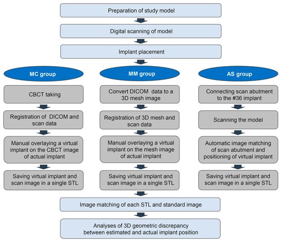
Figure 1.
Workflow for this study. MC: Manual matching on a CBCT image; MM: Manual matching on a mesh model of a CBCT image; AS: Automatic matching on a scan abutment of the scan image.
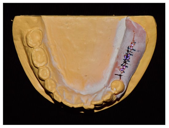
Figure 2.
Study model.
To locate the position of the placed implant for the first molar, the following three different methods were chosen: manual matching on a CBCT image (MC group), manual matching on a mesh model of a CBCT image (MM group), and automatic matching on a scan abutment of the scan image (AS group). To condition the MC group (Figure 3a), radiographic images of the anatomic structures and implants were obtained using a CBCT system (PaXFlex3D, Vatech, Hwasung, Korea) with a field of view of 120 × 85 mm, a voxel size of 0.2 mm, and exposure conditions of 80 kVp and 8 mA, with resulting images saved in the digital imaging and communications in medicine (DICOM) format. The DICOM data and surface scans were exported to an implant planning software program (R2GATE 2.0, MegaGen, Daegu, Korea), where the two 3D images were then merged. A virtual implant was then created and manually overlaid onto the position of the actual implant on the radiographic image. The determined position of the virtual implant was combined with the surface scan image and saved as a single standard tessellation language (STL) file. To condition the MM group (Figure 3b), the CBCT data of the study model were converted into a 3D reconstruction mesh image using an image-control software program (Mimics, Materialise, Leuven, Belgium). The 3D mesh image and surface scan data were merged in the implant-planning software. Subsequently, a virtual implant was manually overlaid on the reconstructed image of the actual implant; these were then saved together as a single STL file. Lastly, to condition the AS group (Figure 3c), a scan abutment (4.0 mm in diameter and 9.0 mm in height; AnyOne scan abutment, MegaGen, Daegu, Korea) was connected to the implant in the dentiform and digitized using the desktop scanner. This scan image was transferred as an STL file to a dental design software program (IDC D1, Amann Girrbach, Koblach, Austria), where the position of the actual implant was calculated by matching the image of the scan abutment. The image of the virtual scan abutment was provided by the manufacturer of the implant and was automatically matched onto the scanned image of the scan abutment using the embedded best-fit registration module of the CAD software program. A virtual implant image was then created based on the position of the virtual scan abutment. Finally, the virtual implant was combined with the surface model scan and saved as a single STL file.
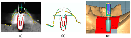
Figure 3.
Implant detection methods. (a) Manual matching of a virtual implant image to the position of the radiographic image of the actual implant. (b) Manual matching of a virtual implant image to the position of the reconstructed mesh image of the actual implant. (c) Automatic creation of the virtual implant using scan abutment, digitization, and automatic image-matching.
Thirty dental clinicians participated in this study to validate the three detection methods for locating the actual implants. All attendees were blinded to the purpose of this study and performed each method in a random order (n = 30 per group; total n = 90). The study design was approved by the institutional review board of Kyungpook National University Dental Hospital (2019-03-03-00).
The accuracy of the geometric position of the virtual implant with respect to the position of the actual implant was evaluated by comparison with a reference image in an image analysis software program (Geomagic Design X; 3D Systems, Morrisville, NC, USA). The reference image was created by directly scanning the surface of the implant in the dentiform model (Figure 4). First, the buccal side of the dentiform model around the implant was removed to expose the threads on half of the implant surface. Next, the trimmed model was digitized and a virtual implant image was precisely superimposed on the actual implant, matching congruent surface areas on the implant. The determined position of the implant was then used as the reference position for the analyzing the accuracy of each detection method.
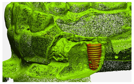
Figure 4.
Reference image of the implant position.
For discerning the accuracy of the implant detection methods, the resulting STL files from each group were matched to the reference image based on the images of the remaining teeth in the model. The geometric discrepancy between the estimated and actual positions was then analyzed in a 3D fashion (Figure 5). The discrepancy parameters of interest included linear deviation, vertical deviation, and angular deviation; among these, linear deviation was measured at the implant platform and bottom levels, vertical deviation was measured at the implant’s center level, and angular deviation was measured using the centerlines of the implants in 3D. All measurements were carried out by a single investigator.
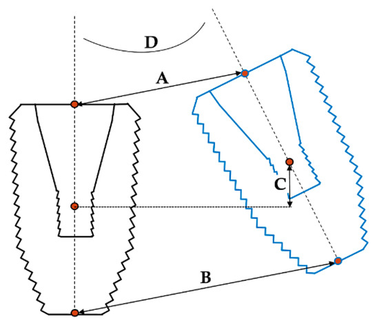
Figure 5.
Discrepancy parameters between the estimated and actual 3D positions of implant. A: Linear deviation at the platform; B: linear deviation at the bottom; C: vertical deviation; D: angular deviation.
All statistical analyses were carried out using a statistical software package (IBM SPSS Statistics v25.0 for Windows, IBM, Armonk, NY, USA). The error of each detection method is expressed as mean ± standard deviation and visualized using a scatterplot. After determining the normal distribution (Shapiro–Wilk test) and equal variances (Levene test), one-way analysis of variance (ANOVA) and Tukey’s post-hoc test were used to compare the results of different groups. The statistical significance level was set at 0.05.
3. Results
The geometric discrepancies between the estimated and actual positions of the implant in each group are shown in Table 1. In general, the linear, vertical, and angular deviations were largest in the MC group, followed by slightly smaller deviations in the MM group and the AS group. The ANOVA results showed that all deviations were markedly smaller in the AS group and in the MC group (p < 0.001). Regarding the linear discrepancy, the linear deviation at the bottom of the MC group was the largest (0.58 ± 0.15 mm), whereas the vertical deviation of the AS group was the smallest (0.04 ± 0.02 mm). Post-hoc analysis revealed that the linear deviations at the bottom were not statistically different between the MM and AS groups. In the vertical and angular deviations, there were no statistical differences apparent between the MC and MM groups.

Table 1.
Values of geometric discrepancy between the estimated and actual positions of the implant using different detection methods.
In terms of measurement parameters, the linear deviations were larger at the bottom than at the platform level in the MC and AS groups but not in the MM group. Scatterplots of the distribution of the measurement values show that the interoperator variability was smallest in the AS group for all deviation parameters (Figure 6). Conversely, the variability of measurement values among operators was larger in both the MC and MM groups, showing a wide distribution of data points.
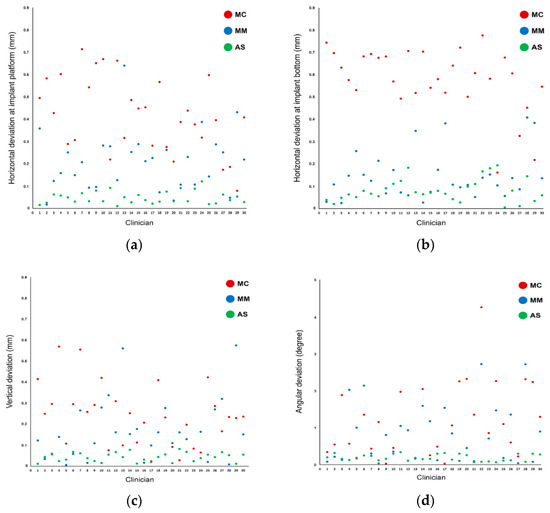
Figure 6.
Scatterplot of deviations among the different methods used for implant detection: (a) linear deviations at the platform; (b) linear deviations at the bottom; (c) vertical deviations; (d) angular deviations.
4. Discussion
We attempted to examine the accuracy of postoperative methods for detecting the actual position of an implant and to compare the accuracy profiles of several methods using multiple raters. The deviations and variations in measurement values derived from each method were significantly different among groups in this study. Specifically, the method relying on automatic image-matching of the scan abutment had more accurate outcomes than the radiographic and mesh data-based methods. Thus, the null hypothesis stating that the accuracy of detection methods for locating the implant position does not differ according to the method was rejected. Ma et al. [23] previously evaluated the positioning of implants using both the CBCT and scan abutment methods and also observed a level of disagreement between the outputs of the two methods that corresponds well with the findings of the present study. Notably, we detailed the methodologies for evaluating the agreement of the planned and actual positions of implants. When the implant position is planned before the surgery, it is assumed that the actual implants will be positioned in the planned places in the oral cavity. The importance of agreement between the planned and actual positions of implants has been emphasized as a method to reduce biological, esthetic, and prosthodontic complications [2,3,5]. It is necessary for clinicians to know what they can expect in terms of the error profile of guided surgery systems that they are using in the clinic. To investigate the error, an accurate postoperative method for locating the placed implants is required. Good methodological accuracy is also important for evaluating the reliability of reports that measure the accuracy of implant placement in the literature. Based on the findings of the present study, we recommend using scan abutments for locating the actual implant position to minimize possible errors derived from the evaluation method. Special care should also be taken in interpreting the results of the accuracy of implant placement reported in other studies if these investigations adopted CBCT-based manual matching methods for their evaluations.
The scan abutment method has commonly been used in the field of prosthodontics [24,25]. To design a customized abutment, the position of the implant placed in the oral cavity should be visualized in a CAD software program together with the adjacent oral structures. Scan abutments constitute a method for transferring the 3D position of the implant inside the oral cavity into the software program [26]. The scan abutment is connected to the actual implant and digitized using optical scanners [27]; the scan data are then delivered to a dedicated design software program, where a virtual implant is created at the identical position of the actual implant by using an automatic image-matching process for the scan abutment. After this registration process, a customized abutment is designed based on the position of the virtual implant. The tracking function of the scan abutment can be applied for evaluation of the accuracy of implant placement. This analysis method is more applicable in cases of computer-guided implant surgery because the information on the planned implant’s position is already saved within the planning software program. The digitally obtained position of actual implants can be conveniently compared with the planned position in 3D. Consequently, the use of scan abutments for investigating the position of actual implants has been explored in recent studies [7,20]. Tallarico et al. [7] performed a multicenter clinical study where scan abutments were tightened onto implants placed within the oral cavity and intraoral scans were taken to locate the position of the implants. Kholy et al. [20] used scan abutments to evaluate the postoperative positions of implants placed in an effort to investigate the effects of the sleeve structure of the guide template on the accuracy of a static computer-assisted implant surgery system.
The inaccuracy of CBCT-based detection methods is largely related to the image quality of radiography. Computed tomography implies an image-distortion phenomenon and the appearance of image artifacts because of zero transmission projections and beam-hardening effects [28]. When an X-ray image is projected onto metals, photon starvation can be triggered by full absorption of the low-energy X-ray quanta and interference occurs between the scattered photons [29]. Although several approaches—such as the projection of higher-energy quanta, use of a dual-energy system, and specific algorithms incorporating adaptive filtering of the raw data—have been introduced to reduce the image distortions and artifacts [30,31], inherent limitations remain inevitable with any CBCT method. The quality of radiographic and 3D reconstruction images obtained by CBCT is also dependent on certain acquisition parameters, such as the object’s position, field of view, tube voltage, tube current, device type, voxel size, signal-to-noise ratio, and gray value thresholds of segmentation [32,33]. Thus the accuracy of CBCT-based detection methods may vary according to existing image artifacts and the scanning parameter conditions. Moreover, the radiographic image of implants is magnified and the lines in the image are blurred because of limited image resolution and the characteristics of the bitmap format [34]. When the radiographic image of an implant is converted to the mesh format, the contours of the implant are drawn with lines in the vector format in the analysis software. Clear contour lines of the implants could enhance image-matching between the planned and actual implant positions by reducing the presumptive selection of implant boundaries [35]. However, because the shape of the implant in the mesh format is fundamentally dependent upon the quality of the radiographic image of CBCT, the process of image conversion may not significantly improve the accuracy of the methodology in detecting the position of the implants. The results of our study also showed large linear and angular deviations of the implant position in the mesh model image.
The errors in the scan abutment group might be derived from the manual tightening of the scan abutment and the image-matching algorithm of the CAD software program. Although manual tightening of the scan abutment using finger drivers is commonly performed in both the clinic setting and in research [20], the adaptation of the scan abutment to the implant could differ among operators. Accordingly, the use of electric torque drivers to eliminate the effects of unwanted confounding factors may be recommended. The accuracy of image-matching of the scan body in the software program should also be elucidated to systematically analyze the cause of errors resulting from the scan abutment method. One limitation of this study is that the in vitro nature of this investigation did not allow for the consideration of relevant clinical factors, such as the hard and soft tissue, various edentulous situations, and patient movement. Thus, further comprehensive randomized controlled clinical studies are necessary to confirm the results of this validation study.
5. Conclusions
Within the context of the limitations of this study, the automatic matching method using scan abutments was more accurate than the manual matching methods using CBCT and mesh images for locating the actual position of the implant. Digital tools enhance the reliability of successfully detecting the actual implant position. The use of scan abutments is recommended for postoperative assessments of the accuracy of implant placement in computer-guided implant surgery.
Author Contributions
Conceptualization, methodology, data curation, formal analysis, investigation, S.-M.O. and D.-H.L.; writing—original draft preparation, S.-M.O.; writing—review and editing, D.-H.L.; supervision, D.-H.L. All authors have read and agreed to the published version of the manuscript.
Funding
This research received no external funding.
Conflicts of Interest
The authors declare no conflict of interest.
References
- Ozan, O.; Turkyilmaz, I.; Ersoy, A.E.; McGlumphy, E.A.; Rosenstiel, S.F. Clinical accuracy of 3 different types of computed tomography-derived stereolithographic surgical guides in implant placement. J. Oral. Maxillofac. Surg. 2009, 67, 394–401. [Google Scholar] [CrossRef] [PubMed]
- El Askary, A.S.; Meffert, R.M.; Griffin, T. Why do dental implants fail? Part I. Implant. Dent. 1999, 8, 173–185. [Google Scholar] [CrossRef] [PubMed]
- El Askary, A.S.; Meffert, R.M.; Griffin, T. Why do dental implants fail? Part II. Implant. Dent. 1999, 8, 265–277. [Google Scholar] [CrossRef] [PubMed]
- Widmann, G.; Stoffner, R.; Schullian, P.; Widmann, R.; Keiler, M.; Zangerl, A.; Puelacher, W.; Bale, R.J. Comparison of the accuracy of invasive and noninvasive registration methods for image-guided oral implant surgery. Int. J. Oral Maxillofac. Implant. 2010, 25, 491–498. [Google Scholar]
- Ardekian, L.; Dodson, T.B. Complications associated with the placement of dental implants. Oral. Maxillofac. Surg. Clin. N. Am. 2003, 15, 243–249. [Google Scholar] [CrossRef]
- Walton, J.N. Altered sensation associated with implants in the anterior mandible: A prospective study. J. Prosthet. Dent. 2000, 83, 443–449. [Google Scholar] [CrossRef]
- Tallarico, M.; Kim, Y.-J.; Cocchi, F.; Martinolli, M.; Meloni, S.M. Accuracy of newly developed sleeve-designed templates for insertion of dental implants: A prospective multicenters clinical trial. Clin. Implant Dent. Relat. Res. 2019, 21, 108–113. [Google Scholar] [CrossRef]
- Nickenig, H.J.; Eitner, S. Reliability of implant placement after virtual planning of implant positions using cone beam CT data and surgical (guide) templates. J. Craniomaxillofac. Surg. 2007, 35, 207–211. [Google Scholar] [CrossRef]
- Lal, K.; White, G.S.; Morea, D.N.; Wright, R.F. Use of stereolithographic templates for surgical and prosthodontic implant planning and placement. Part I. The concept. J. Prosthodont. 2006, 15, 51–58. [Google Scholar] [CrossRef]
- Ganz, S.D. Three-dimensional imaging and guided surgery for dental implants. Dent. Clin. N. Am. 2015, 59, 265–290. [Google Scholar] [CrossRef]
- Nokar, S.; Moslehifard, E.; Bahman, T.; Bayanzadeh, M.; Nasirpouri, F.; Nokar, A. Accuracy of implant placement using a CAD/CAM surgical guide: An in vitro study. Int. J. Oral Maxillofac. Implant. 2011, 26, 520–526. [Google Scholar]
- Kim, H.J.; Kim, H.J.; Moon, S.Y. A Prospective Study on Accuracy of Computer-Based Fully Guided Versus Pilot-Guided Implant Surgery. Appl. Sci. 2020, 10, 1975. [Google Scholar] [CrossRef]
- Oh, S.-M.; Kim, J.-W.; Choi, S.-Y.; Lee, D.-H. Full-Mouth Rehabilitation with Bone-Level Implant Guide and Monolithic Zirconia Prosthesis for Fibular Free Flap Reconstruction: A Case History Report. Int. J. Prosthodont. 2018, 31, 573–576. [Google Scholar] [CrossRef] [PubMed]
- Schnutenhaus, S.; Gröller, S.; Luthardt, R.G.; Rudolph, H. Accuracy of the match between cone beam computed tomography and model scan data in template-guided implant planning: A prospective controlled clinical study. Clin. Implant Dent. Relat. Res. 2018, 20, 541–549. [Google Scholar] [CrossRef]
- Lin, C.-C.; Ishikawa, M.; Huang, B.-H.; Huang, M.-S.; Cheng, H.-C.; Maida, T.; Nezu, T.; Endo, K. In Vitro Accuracy of Static Guided Implant Surgery Measured by Optical Scan: Examining the Impact of Operator Experience. Appl. Sci. 2020, 10, 2718. [Google Scholar] [CrossRef]
- Raico Gallardo, Y.N.; da Silva-Olivio, I.R.T.; Mukai, E.; Morimoto, S.; Sesma, N.; Cordaro, L. Accuracy comparison of guided surgery for dental implants according to the tissue of support: A systematic review and meta-analysis. Clin. Oral. Implant. Res. 2017, 28, 602–612. [Google Scholar] [CrossRef]
- Kernen, F.; Benic, G.I.; Payer, M.; Schär, A.; Müller-Gerbl, M.; Filippi, A.; Kühl, S. Accuracy of Three-Dimensional Printed Templates for Guided Implant Placement Based on Matching a Surface Scan with CBCT. Clin. Implant Dent. Relat. Res. 2016, 18, 762–768. [Google Scholar] [CrossRef]
- Murat, S.; Kamburoğlu, K.; Özen, T. Accuracy of a newly developed cone-beam computerized tomography-aided surgical guidance system for dental implant placement: An ex vivo study. J. Oral Implantol. 2012, 38, 706–712. [Google Scholar] [CrossRef]
- Vercruyssen, M.; Hultin, M.; Van Assche, N.; Svensson, K.; Naert, I.; Quirynen, M. Guided surgery: Accuracy and efficacy. Periodontology 2000 2014, 66, 228–246. [Google Scholar] [CrossRef]
- El Kholy, K.; Janner, S.F.M.; Schimmel, M.; Buser, D. The influence of guided sleeve height, drilling distance, and drilling key length on the accuracy of static Computer-Assisted Implant Surgery. Clin. Implant Dent. Relat. Res. 2019, 21, 101–107. [Google Scholar] [CrossRef]
- Sarment, D.P.; Sukovic, P.; Clinthorne, N. Accuracy of implant placement with a stereolithographic surgical guide. Int. J. Oral. Maxillofac. Implants. 2003, 18, 571–577. [Google Scholar]
- Mai, H.-N.; Choi, S.-Y.; Lee, S.-T.; Lee, D.-H. Optimizing accuracy in computer-guided implant surgery with a superimposition-anchor microscrew system: A clinical report. J. Prosthet. Dent. 2018, 120, e1–e789. [Google Scholar] [CrossRef] [PubMed]
- Ma, B.; Park, T.; Chun, I.; Yun, K. The accuracy of a 3D printing surgical guide determined by CBCT and model analysis. J. Adv. Prosthodont. 2018, 10, 279–285. [Google Scholar] [CrossRef]
- Mizumoto, R.M.; Yilmaz, B. Intraoral scan bodies in implant dentistry: A systematic review. J. Prosthet. Dent. 2018, 120, 343–352. [Google Scholar] [CrossRef] [PubMed]
- Jeon, J.-H.; Hwang, S.-S.; Kim, J.-H.; Kim, W.-C. Trueness and precision of scanning abutment impressions and stone models according to dental CAD/CAM evaluation standards. J. Adv. Prosthodont. 2018, 10, 335–339. [Google Scholar] [CrossRef] [PubMed]
- Buda, M.; Bratos, M.; Sorensen, J.A. Accuracy of 3-dimensional computer-aided manufactured single-tooth implant definitive casts. J. Prosthet. Dent. 2018, 120, 913–918. [Google Scholar] [CrossRef]
- Marghalani, A.; Weber, H.P.; Finkelman, M.; Kudara, Y.; El Rafie, K.; Papaspyridakos, P. Digital versus conventional implant impressions for partially edentulous arches: An evaluation of accuracy. J. Prosthet. Dent. 2018, 119, 574–579. [Google Scholar] [CrossRef]
- Grant, G.T.; Campbell, S.D.; Masri, R.M.; Andersen, M.R. Glossary of Digital Dental Terms: American College of Prosthodontists. J. Prosthodont. 2016, 25 (Suppl. 2), S2–S9. [Google Scholar] [CrossRef] [PubMed]
- Barrett, J.F.; Keat, N. Artifacts in CT: Recognition and avoidance. Radiographics 2004, 24, 1679–1691. [Google Scholar] [CrossRef]
- Bamberg, F.; Dierks, A.; Nikolaou, K.; Reiser, M.F.; Becker, C.R.; Johnson, T.R. Metal artifact reduction by dual energy computed tomography using monoenergetic extrapolation. Eur. Radiol. 2011, 21, 1424–1429. [Google Scholar] [CrossRef]
- Watzke, O.; Kalender, W.A. A pragmatic approach to metal artifact reduction in CT: Merging of metal artifact reduced images. Eur. Radiol. 2004, 14, 849–856. [Google Scholar]
- Park, S.W.; Yoon, R.G.; Lee, H.; Lee, H.J.; Choi, Y.D.; Lee, D.H. Impacts of Thresholds of Gray Value for Cone-Beam Computed Tomography 3D Reconstruction on the Accuracy of Image Matching with Optical Scan. Int. J. Environ. Res. Public Health 2020, 17, 6375. [Google Scholar] [CrossRef] [PubMed]
- Ye, N.; Jian, F.; Xue, J.; Wang, S.; Liao, L.; Huang, W.; Yang, X.; Zhou, Y.; Lai, W.; Li, J.; et al. Accuracy of in-vitro tooth volumetric measurements from cone-beam computed tomography. Am. J. Orthod. Dentofac. Orthop. 2012, 142, 879–887. [Google Scholar] [CrossRef] [PubMed]
- Jianwu, X.; Qi-Zhi, S.; Jie, Y.; Jin, Z.; Xiaopeng, D. CAD Graphic Preview and Interaction of the Mould Collaborative Design. Procedia Eng. 2011, 24, 634–637. [Google Scholar]
- Mai, H.-N.; Lee, K.E.; Ha, J.-H.; Lee, D.-H. Effects of image and education on the precision of the measurement method for evaluating prosthesis misfit. J. Prosthet. Dent. 2018, 119, 600–605. [Google Scholar] [CrossRef] [PubMed]


Publisher’s Note: MDPI stays neutral with regard to jurisdictional claims in published maps and institutional affiliations. |
© 2020 by the authors. Licensee MDPI, Basel, Switzerland. This article is an open access article distributed under the terms and conditions of the Creative Commons Attribution (CC BY) license (http://creativecommons.org/licenses/by/4.0/).