Abstract
Background: There are a few biomechanical studies that describe posterior fixation methods with pedicle screws (PS) and lateral mass screws (LMS); the combination of both screw types and their effect on an allograft spacer in a surgically treated cervical segment is unknown. Methods: Finite element model (FEM) analyses were used to investigate the effects of a hybrid technique using posterior PS and LMS. Stress distribution and subsidence risk from a combination of screws under hybrid motion control conditions, including flexion, extension, axial rotation, and lateral bending, were investigated to evaluate the biomechanical characteristics of different six-screw combinations. Findings: The load sharing on the allograft spacer in flexion mode was highest in the LMS model (74.6%) and lowest in the PS model (35.1%). The likelihood of subsidence of allograft spacer on C6 was highest in the screws from the distal LMS (type 5) model during flexion and extension (4.902 MPa, 30.1% and 2.189 MPa, 13.4%). In lateral bending, the left unilateral LMS (type 4) model screws on C5 (3.726 MPa, 22.9%) and C6 (2.994 MPa, 18.4%) yielded the greatest subsidence risks, because the lateral bending forces were supported by the LMS. In counterclockwise axial rotation, the left unilateral LMS (type 4) model screws on C5 (3.092 MPa, 19.0%) and C6 (3.076 MPa, 18.9%) demonstrated the highest subsidence risks. Conclusion: The asymmetrical ipsilateral use of LMS and posterior PS in lateral bending and axial rotation demonstrated the lowest stability and greatest subsidence risk. We recommend bilateral symmetrical insertion of LMS or posterior PS and posterior PS on distal vertebrae for increased stability and reduced risk of allograft spacer subsidence.
1. Introduction
Advanced surgical techniques for combined anterior and posterior surgery to treat complex cervical conditions that are associated with deformity and neurologic deficiencies are increasing [1,2]. To improve biomechanical outcomes, an intraoperative radiologic device such as O-arm could be used in a hybrid technique with posterior pedicle screws (PS) and lateral mass screws (LMS) [3]. In a clinical setting, asymmetrical cervical pedicle screw placement is not uncommon and depends on both the vertebral artery anomaly and the pedicle anatomy [4,5]. Although there are a few biomechanical studies that describe posterior fixation methods with LMS and posterior PS [6,7,8,9], the combination of both screw types and their effect on an allograft spacer in a surgically treated cervical segment is unknown.
Here, we used finite element model (FEM) analyses to investigate the load sharing ratio between allograft spacers and different posterior fixation method combinations that are known to be closely associated with the fusion rate. We compared stability by analyzing the Peak von Mises stress of the allograft spacers and the yielding risk of peri-screw bone under hybrid motion control conditions, including flexion, extension, axial rotation, and lateral bending.
2. Materials and Methods
2.1. FEM of an Intact Cervical Spine
A previously validated three-dimensional intact cervical spinal segment model of C3–6 in a 54-year-old male subject was used [9,10]. The geometrical data of the multi-segmental cervical model were reconstructed from computed tomography (CT) images. The scanner operated at the following settings: ultra-high resolution with a transverse slice thickness of 0.5, and width of the pixel was 0.429 mm.
The cervical Finite Element (FE) model included cortical bone, cancellous bone, posterior elements, annulus fibrosus, nucleus pulposus, and facet. In addition, anterior longitudinal ligaments, posterior longitudinal ligaments, intraspinous ligaments, ligament flava, and capsular ligaments were included. Ligament insertion points were matched from CT image. The spinal ligaments adopted the nonlinear load-displacement material property for the physiological nonlinear behavior of the ligaments (Table 1) [10,11]. The cortical bone of the vertebrae was separately modeled from the inner cancellous bone because of its high stiffness. Although the thickness of the cortical bone varies depending on each vertebral body and on the location, an average value of 0.5 mm was used for the shell thickness in this study [12]. The vertebrae and discs were meshed using “eight-node brick” elements, and the posterior element was meshed using for-node brick elements. The material properties were assumed to be homogeneous and isotropic (Table 2) [13,14,15]. The mesh convergence was performed to confirm adequate mesh density among variable element sizes from 0.1 to 2.0 mm. Finally, a 0.5-mm element size was applied in our surgical model for the prediction of FE analysis results (implant and periphery, element size—0.5 mm; the others, 2 mm). No unusual stress patterns were presented in this study for this setting.

Table 1.
The nonlinear material properties of the ligaments used in the Finite Element model [10].
Table 2.
Material properties.
The intervertebral disc was consisted of an annulus fibrosus and a nucleus pulposus bounded by the endplates. The fiber contents in the annulus fibrosus were modeled using tension-only truss elements, which carry only tensile forces. The annulus fiber was arranged in an alternating crisscross manner with an about 25° orientation [16,17]. The facet cartilage joints were modeled 45° from the horizontal plane and soft frictionless, with an initial gap of 0.5 mm based upon CT imaging [16]. The segment angles used to create the cervical spine curvature for the model were as follows: C3–4: 4.5°, C4–5: 1.87°, and C5–6: 3.94° [18]. For this study, the general-purpose Finite element analysis (FEA) package ABAQUS (Abaqus 2017, Dassault Systèmes Simulia Corp., Providence, RI, USA.) nonlinear geometry parameter (NLGEON = ON) in the ABAQUS step module was used.
2.2. LMS and PS Combination Model with Allograft Spacer
The allograft spacer was constructed based on measuring the CornerstoneTM ASR (Medtronic Sofamor Danek, Memphis, TN, USA) using SolidWorks CAD drawings (Solidworks 2013, Dassault Systemes Solidworks Corporation, Waltham, MA, USA) and imported into ABAQUS to generate elements of 3D geometry. The mesh size of the allograft spacer was 0.5 mm. The boundary condition of the allograft spacer between the cortical bone and cancellous bone was accomplished through a “tie”. Then, the meshed allograft spacer model was inserted into the C5–6 disc space of the previously constructed intact cervical FEM. The spacer had a length of 14 mm, a height of 7 mm, and a lordotic angle of 7°, which were the best dimensions to fit the vertebral anatomy at the C5–6 level for the cervical model being used.
The allograft spacers were inserted via an anterior surgical approach, which was previously described [22,23,24]. By simulating the surgical procedure, the anterior longitudinal ligament, the posterior longitudinal ligament, the superior and inferior endplates, and the anterior and posterior portions of the annulus fibrosus were excised. Then, the allograft spacer was positioned at the anterior margin of the vertebral body. Since our model was aimed at simulating the biomechanical behaviors after bony fusion, specific constraint conditions were imposed, especially at the bone-implant interface. In this study, the interface behavior was accomplished via a “tie” contact condition, which enabled the allograft spacer and vertebrae to be permanently bonded together and fully constrained.
By incorporating the Poseidon cervical pedicle screw system (Medyssey, Jecheon, Korea) for posterior fixation, each lateral mass screw, pedicle screw, and their combination models were set. The PS was 28 mm in length and 3.5 mm in diameter, and the LMS was 14 mm in length and 3.5 mm in diameter. The rod had a thickness of 3.7 mm. Each screw was inserted as described below. The LMS position was defined as 1-mm medial and 1-mm cephalad in relation to the midpoint of the lateral mass. The insertion angle was set to 28° in the lateral direction and 15° in the superior direction. The PS position was set to 1-mm lateral to the center of the articular mass and near the end of the superior articular process. The C5–C6 segment was 40° medial and sagittally parallel to the inferior endplate [25,26].
Six types of postoperative posterior fixation models (Type 1: all LMS, Type 2: all pedicle screws (PS), Type 3: left (Lt) PS and right (Rt) LMS combination, Type 4: Lt LMS and Rt PS, Type 5: upper PS and lower LMS, and Type 6: upper LMS and lower PS) were constructed by modifying the intact model to simulate device implantation at C5–C6 (Figure 1).
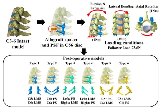
Figure 1.
Finite element model and the six models with lateral mass screws (LMS) and pedicle screws (PS). Type 1: all LMS, Type 2: all PS, Type 3: left (Lt) PS and right (Rt) LMS, Type 4: Lt LMS and Rt PS, Type 5: upper PS and lower LMS, and Type 6: upper LMS and lower PS.
2.3. Loading and Boundary Conditions
The inferior endplate of the most caudal vertebra (C7) was fixed in all degrees of freedom, while loads were applied to the superior endplate of the most cephalic vertebra (C3). A compressive load of 73.6 N was used to approximate the weight of the head and local muscle stabilization during daily activity [27,28]. Six constrained degrees of freedom (translation and moment) at C6 were investigated after first applying a compressive load of 73.6 N and then a pure moment of 1.0 Nm. We divided the anterior (allograft spacer, annulus matrix, and fibers) and posterior sections (facet joint and posterior fixation constructs (PFCs)) and calculated the ratio after measuring the normal force in the x, y, and z directions of each surface node. In addition, the stability of the allograft spacer and bone was confirmed by measuring the Peak von Mises Stress (PVMS) of the allograft spacer and the maximum principle strain of the peri-screw bone. To confirm the subsidence potential of the treatment devices, the PVMS of the bone surface in contact with the treatment device was analyzed assuming a bone yield stress ratio of 16.3 MPa [9,29].
3. Results
3.1. Load Sharing Between Posterior Fixation Constructs and the Allograft Spacer
In flexion mode, the load sharing on the allograft spacer was highest in the Type 1 model (74.6%; Figure 2). When combined with any number of PS, the load sharing on the allograft spacer decreased. In extension mode, the load sharing on the allograft spacer was lowest in the Type 5 (14.4%) model and highest in the Type 1 LMS-only model (25.3%). In the lateral bending mode, the load sharing on the allograft spacer was highest in the Type 6 model (60.9%) and lowest in the Type 3 model (23.5%), where the compressed side during lateral bending was supported by the PS. In the counterclockwise axial rotation mode, all models except Type 2 demonstrated increased physiologic loading on the allograft spacers. The load sharing on the allograft spacer was highest in the Type 1 model (42.2%) and lowest in the Type 2 model (19.9%).
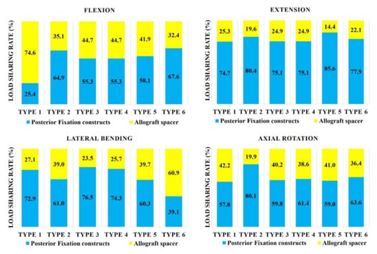
Figure 2.
Load sharing on allograft spacers and posterior fixation constructs. Type 1: all LMS, Type 2: all PS, Type 3: left (Lt) PS and right (Rt) LMS, Type 4: Lt LMS and Rt PS, Type 5: upper PS and lower LMS, and Type 6: upper LMS and lower PS.
3.2. Effect of LMS and PS Combinations on the Allograft Spacer and Posterior Fixation Stress Distributions
In flexion mode, the PVMSs of the allograft spacer and PFCs were lowest in the Type 2 model (Figure 3). In extension mode, the PVMS was highest in the allograft spacers in the Type 3 and 4 models and the PFCs in the Type 5 and 6 models. During lateral bending, the PVMSs of the allograft spacers and PFCs were lowest in the Type 2 and 3 models. In the axial rotation mode, the PVMSs of the allograft spacers and PFCs were lowest in the Type 2 model. The PVMSs were highest in type 3 of the PFCs and in Type 4 of the allospacer.
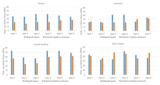
Figure 3.
The Peak von Mises stress on the allograft spacers and posterior fixation constructs were dependent on the plate-screw combination. Type 1: all LMS, Type 2: all PS, Type 3: left (Lt) PS and right (Rt) LMS, Type 4: Lt LMS and Rt PS, Type 5: upper PS and lower LMS, and Type 6: upper LMS and lower PS.
3.3. Effect of Posterior Fixation Constructs on Allograft Spacer Subsidence Risk
In general, the vertebra with LMS exhibited a higher risk of subsidence independent of the vertebra level. The likelihood of subsidence of the allograft spacer was calculated on the basis of the yield strength of the C5 and C6 vertebral body cancellous bone of 16.3 MPa (Figure 4).
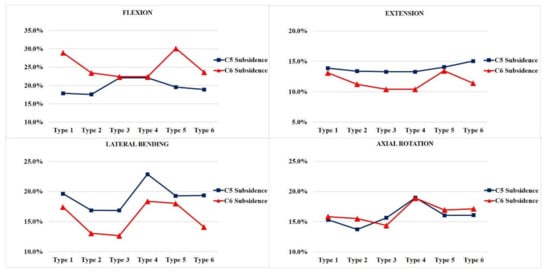
Figure 4.
The subsidence risk analysis of the allograft spacers on C5 and C6. Type 1: all LMS, Type 2: all PS, Type 3: left (Lt) PS and right (Rt) LMS, Type 4: Lt LMS and Rt PS, Type 5: upper PS and lower LMS, and Type 6: upper LMS and lower PS.
In flexion modes, the allograft spacer subsidence risk on C6 was highest in the Type 5 (4.902 MPa, 30.1%) model, where the LMS were bilaterally inserted in the lower vertebra. On the C5 vertebra, Type 3 and 4 (ipsilateral hybrid models) (3.598 MPa, 22.1%) had the highest subsidence risks due to asymmetric physical loading and the weaker support from LMS compared to PS.
In the extension mode, the Type 6 model (2.45 MPa, 15.0%) yielded the highest subsidence risk on C5, and the Type 5 model (2.189 MPa, 13.4%) yielded the highest subsidence risk on the C6. During lateral bending, the Type 3 model (2.746 MPa, 16.8%) had the lowest projected subsidence risk on C5 and (2.061 MPa, 12.6%), also, on C6. This can be explained by a PS counterforce opposing the lateral bending force. Contrarily, in the Type 4 model, the lateral bending force was supported by the lateral mass screw. Accordingly, the highest subsidence risks (3.726 MPa, 22.9%) on C5 and (2.994 MPa, 18.4%) C6 were associated with the Type 4 model, because asymmetry on the LMS side caused excessive LMS-side compression forces. In the counterclockwise axial rotation, the Type 4 model (3.092 MPa, 19.0%) had the highest risk of subsidence on C5 and (3.076 MPa, 18.9%) C6. This model had the PS and LMS parallel to the counterclockwise rotation force, which would enable pulling forces that could displace the screws. The Type 2 model, which was all PS, had the lowest subsidence risk during counterclockwise rotation.
3.4. Distribution of Screw-Bone Interface Stresses
In all models, no complete yield of cancellous bone occurred, which was related to screw loosening. The yield strain of cervical cancellous bone was 0.0081. The screw-bone interface stresses increased at the LMS insertion site near the cortex hole. In general, the whole-body stress distribution was on the LMS-inserted side within the same vertebra and the LMS-inserted vertebral body. The highest stress parts, which were dependent on the fixation and motion, are indicated with red arrows in Figure 5.
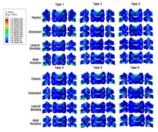
Figure 5.
Posterior and lateral views of the Peak von Mises stress distributions on the screw-bone interface. On the LMS side, the stress load of the vertebral body is demonstrated, but on the PS side, the stress shielding of the vertebral body by PS is seen. *Red arrows indicate the highest stress distribution. Type 1: all LMS, Type 2: all PS, Type 3: left (Lt) PS and right (Rt) LMS, Type 4: Lt LMS and Rt PS, Type 5: upper PS and lower LMS, and Type 6: upper LMS and lower PS.
3.5. Distribution of the Peak von Mises Stress on Posterior Fixation Constructs
In general, the Peak von Mises stress of a screw was higher in the LMS than the PS (Figure 6). The Type 2 model had the lowest calculated PVMS in all motion modes. In flexion and extension modes, when both LMS and PS were included, the Type 3 and 4 models demonstrated the highest PVMS, which occurred around the C5 LMS neck area. In the lateral bending mode, the Type 6 model demonstrated the highest PVMS near the C6 PS rod. Additionally, in the lateral bending mode, the Type 2 model demonstrated the lowest PVMS, which occurred near the inlet of the vertebral body pedicle. During the axial rotation mode, the Type 3 model had the highest predicted PVMS around the LMS neck on the C6 area. In the Type 6 model, the PVMS was highest near the LMS neck on C5. In this area, the counterforce was applied counterclockwise against the rotation force. All of the models demonstrated very low values with respect to the yield of the strength of titanium (880 MPa).
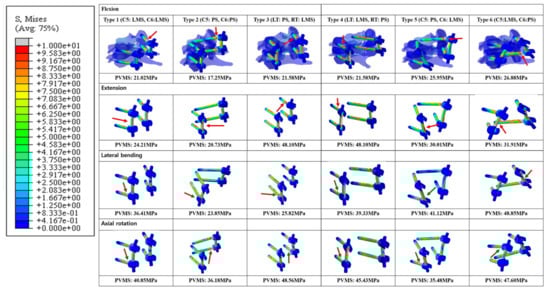
Figure 6.
Posterior and lateral views of the Peak von Mises stress distributions on the screw-bone interface. *Red arrows indicate the highest stress distributions. Type 1: all LMS, Type 2: all PS, Type 3: left (Lt) PS and right (Rt) LMS, Type 4: Lt LMS and Rt PS, Type 5: upper PS and lower LMS, and Type 6: upper LMS and lower PS.
4. Discussion
The treatment for severe spondylotic cervical radiculomyelopathy patients is a combination of lateral mass and pedicle screws that are essential to ensure the biomechanical stability of a surgically treated bone-allograft spacer segment. The screw combination is based on patient-specific anatomical considerations and surgeon preferences [1,30]. Despite the variety of screw combinations that can be used, no study has analyzed how different combinations of lateral mass and posterior pedicle screws affects biomechanical stresses. We compared the different biomechanical stresses on allograft spacers, endplates, the bone-screw interface, and rod screws for different screw combinations.
The combination of a lateral mass and pedicle screw is expected to have different stabilization outcomes during flexion, extension, axial rotation, and lateral bending. Furthermore, deeper insertion of the pedicle screw results in better stabilization.
4.1. Load Distribution and PVMS on Posterior Fixation Constructs and Allograft Spacers
In the current study, the PFCs functioned better in extension than tension during the flexion mode regardless of the LMS and PS. The Type 2 model (PS-only) had lower overall loading on the allograft spacer when compared to other models, except during lateral bending. During flexion, the Type 1 model demonstrated the highest allograft spacer loading, which indicated that the LMS alone could be insufficient to support the vertebral body-allograft spacer constructs under specific circumstances, such as loading in osteoporosis patients. Interestingly, in lateral bending mode, the Type 3 and 4 models, which had support from the PS on the compressed side or the opposite side, demonstrated the lowest loading on the allograft spacers. These data suggest that, on both the compressive and distractive sides, the PS hold the C5–6-allograft spacer construct tightly and resist the lateral bending forces.
In axial rotation, the type 3 model had the highest PVMS on the PFCs, which occurred around the LMS neck due to the direction of the counterclockwise rotation force and relatively weaker support from the LMS on the opposite side. Therefore, the stress on the PS side increased to compensate the weaker support from the LMS. The stress on the PS side also increased but was widely distributed over the entire body of the PS. However, on the LMS side, in the near cortex, which was in contact with the LMS, there was increased bone-interface stress. In this area, screw toggling and loosening are expected (Figure 2, Figure 3, Figure 5 and Figure 6). In contrast, for the Type 4 model, the PVMS on the allograft spacer was the highest. The PVMS on the PFC also increased near the LMS neck area due to the screw direction, which allowed for the counterclockwise rotation of the vertebra that could displace the screws.
It is anticipated that, in flexion mode, the allograft spacer PVMSs are higher than in the PFCs. However, in extension mode, after ipsilateral hybrid insertion of the LMS and the PS (Type 3 and 4 models), the allograft spacer PVMSs increased due to asymmetric physiologic loading when compared to the LMS and PS-only models. In the proximal and distal combinations (Type 5 and 6 models), however, both the PVMS on the allograft spacers and on the PFCs increased. For example, in the Type 6 model, the C6 PS had a stronger column fixation when compared to the C5 LMS. The C6 PS was a source of stiffness against LMS fixation, and the PVMS was highest on the rod near the PS head. In the Type 5 model, the PVMS on the PFCs was the highest on the rods near the distal screws (Figure 6). During lateral bending, the Type 2 and 3 models were supported by the PS on the compressed side and demonstrated the lowest PVMSs on both the allograft spacers and PFCs. When combined with the LMS or when the LMS was used alone on the compressed side, the PVMSs on the allograft spacers and PFCs increased (Figure 2 and Figure 3).
The distribution patterns of the PVMSs on the PFCs are clinically meaningful (Figure 6). Most of LMS exhibited higher PVMSs around the LMS neck area (Type 1, 3, and 4 models), which is the most common area for bone-screw interface loosening. In the PS, the highest PVMSs regions were at the screw neck insertion point and at the pedicle screw–shaft interface. In contrast to the LMS, in the PS, the range of bone-screw contacts are wider and have a decreased risk of bone-screw failure caused by toggling motions.
4.2. Effect of Posterior Fixation Constructs on the Subsidence Risk of Allograft Spacers
The asymmetrical hybrid insertion of LMS and PS, especially in the Type 4 model, had worsening subsidence risks that were dependent on the applied forces, except for extension.
In flexion mode, the Type 1 and 5 models had the highest C6 subsidence risks These results indicate that LMS inserted at C6 are weaker than PS and less able to support the flexion force of the constructs, which would accompany the collapse of the C6 endplate. In contrast, the Type 3 and 4 ipsilateral hybrid models had an increased subsidence risk of C5 due to asymmetric physical loading and the weaker support from LMS compared to PS.
In the extension mode, the LMS demonstrated increase subsidence risk at the insertion level in Type 1, 5, and 6 models. When the LMS were inserted at lower levels, the weakest support resulted in increased C5 and C6 subsidence risks. The LMS on C6 in the Type 5 model are biomechanically insufficient to hold the PS inserted in the C5 vertebral body.
In lateral bending, the PS on the compression side provided the strongest support in the Type 2 and 3 models. However, in the Type 4 model, the asymmetry on the LMS side caused excessive LMS-side compression forces, which yielded the highest C5 and C6 subsidence risks. When the LMS was at a lower level (Type 1 and 5 models), it also led to increased concomitant C5 and C6 subsidence risks. In the axial rotation, the screw direction with respect to the rotational force and the bilateral positioning of the LMS affected the allograft spacer subsidence.
In the current study, as anticipated, the PS constructs were biomechanically stronger than the LMS constructs. As the number of PS added to a construct with LMS increased, the biomechanical stability increased. More specifically, the load distribution, especially in flexion, increased. The only exception was the Type 4 model during lateral bending. However, the results indicated that an asymmetric combination of PS and LMS caused an increased subsidence risk in the Type 4 model in the lateral bending and axial rotation. Therefore, when using a hybrid model with LMS and PS, a spine surgeon should understand that specific screw combinations could negatively affect the postoperative subsidence risk of allograft spacers.
This study had a few limitations that are related to the middle-aged 54-year-old male patient that was the basis for the FEM modeling, which have already been mentioned by other studies. The results do not reflect the condition of the discs and endplates in older female patients who undergo spinal surgery with cervical radiculomyelopathy. In addition, our FEM model only included an allograft spacer-vertebral body fusion model; it did take into account the immediate postoperative status of the allograft spacer-vertebral body interface before bony fusion occurs. Additionally, a 3D intact cervical FE model validated by range of motion (ROM) was utilized in the present study [9,10]. This approach confirmed that the kinematics of the developed FEM reflected real soft tissue functions. However, we evaluated the stress and strain of the peri-screw bone, which could be a different context for the use of this FEM. Therefore, this study could lack sufficient evidence to support the validation of this FEM. Nevertheless, in many biomechanical studies, ROM was utilized to validate and verify models, as well as to predict stress and forces reflective of real-world settings [31,32,33,34,35,36,37].
5. Conclusions
In conclusion, the asymmetrical ipsilateral hybrid use of LMS and PS in lateral bending and axial rotation yielded the worst mechanical stability and a higher allograft spacer subsidence risk. In addition, distal LMS insertion increased the subsidence risk of allograft spacers on C6 in both flexion and extension. Therefore, we recommend the bilateral symmetrical insertion of LMS or PS and PS insertion on distal vertebra for the improved stability and decreased risk of allograft spacer subsidence.
Author Contributions
Conceptualization, S.-B.L., B.H.L., S.-H.M., S.J.L.,T.-H.P., H.-M.L., and Y.-W.K.; methodology, S.-H.M., S.-B.L., Y.-W.K., B.H.L., S.J.L., T.-H.P., and H.-M.L.; software, H.-M.L., S.-B.L., T.-H.P., B.H.L., S.J.L., S.-H.M., and Y.-W.K.; validation, S.-B.L., T.-H.P., B.H.L., S.J.L., H.-M.L., Y.-W.K., and S.-H.M.; formal Analysis, T.-H.P., B.H.L., and S.J.L.; investigation, T.-H.P., S.J.L., and B.H.L.; resources, T.-H.P., B.H.L., and S.J.L.; data curation, S.J.L., T.-H.P., and B.H.L.; writing—original draft preparation, B.H.L.; writing—review and editing, B.H.L.; visualization, S.J.L., T.H.P, and B.H.L.; supervision, H.-M.L., S.J.L., S.-B.L., Y.-W.K., T.-H.P., S.-H.M., and B.H.L.; project administration, T.-H.P., B.H.L., and S.J.L.; and funding acquisition, B.H.L. All authors have read and agreed to the published version of the manuscript.
Funding
This research was funded by NRF-2017R1C1B5017402.
Conflicts of Interest
The authors declare no conflict of interest.
References
- Bram, R.; Fiore, S.; Labiak, J.J.; Davis, R.P. Combined Anterior-Posterior Decompression and Fusion for Cervical Spondylotic Myelopathy. Am. J. Orthop. 2017, 46, E97–E104. [Google Scholar] [PubMed]
- Sethy, S.S.; Ahuja, K.; Ifthekar, S.; Sarkar, B.; Kandwal, P. Is Anterior-Only Fixation Adequate for Three-Column Injuries of the Cervical Spine? Asian Spine J. 2020. [Google Scholar] [CrossRef] [PubMed]
- Ishikawa, Y.; Kanemura, T.; Yoshida, G.; Matsumoto, A.; Ito, Z.; Tauchi, R.; Muramoto, A.; Ohno, S.; Nishimura, Y. Intraoperative, full-rotation, three-dimensional image (O-arm)–based navigation system for cervical pedicle screw insertion. J. Neurosurg. Spine. 2011, 15, 472–478. [Google Scholar] [CrossRef] [PubMed]
- Koller, H.; Hitzl, W.; Acosta, F.; Tauber, M.; Zenner, J.; Resch, H.; Yukawa, Y.; Meier, O.; Schmidt, R.; Mayer, M. In vitro study of accuracy of cervical pedicle screw insertion using an electronic conductivity device (ATPS part III). Eur. Spine J. 2009, 18, 1300–1313. [Google Scholar] [CrossRef] [PubMed]
- Suda, K.; Taneichi, H.; Kajino, T.; Otomo, H.; Moridaira, H.; Toyoda, H.; Kaneda, K. P66. How to Avoid Fatal Vascular Complications Caused by Cervical Pedicle Screws: A New Surgical Strategy and Techniques for Safe Screw Placement. Spine J. 2006, 6. [Google Scholar] [CrossRef]
- Duan, Y.; Wang, H.H.; Jin, A.M.; Zhang, L.; Min, S.X.; Liu, C.L.; Qiu, S.J.; Shu, Q.X. Finite element analysis of posterior cervical fixation. Orthop. Traumatol. Surg. Res. 2015, 101, 23–29. [Google Scholar] [CrossRef]
- Duan, Y.; Zhang, H.; Min, S.X.; Zhang, L.; Jin, A.M. Posterior cervical fixation following laminectomy: A stress analysis of three techniques. Eur. Spine J. 2011, 20, 1552–1559. [Google Scholar] [CrossRef]
- Hong, J.T.; Qasim, M.; Espinoza Orias, A.A.; Natarajan, R.N.; An, H.S. A biomechanical comparison of three different posterior fixation constructs used for C6–C7 cervical spine immobilization: A finite element study. Neurol. Med. Chir. 2013, 54, 727–735. [Google Scholar] [CrossRef][Green Version]
- Kwon, J.-W.; Bang, S.H.; Park, T.H.; Lee, S.-J.; Lee, H.-M.; Lee, S.-B.; Lee, B.H.; Moon, S.-H. Biomechanical comparison of cervical discectomy/fusion model using allograft spacers between anterior and posterior fixation methods (lateral mass and pedicle screw). Clin. Biomech. 2020, 73, 226–233. [Google Scholar] [CrossRef]
- Jung, T.-G.; Woo, S.-H.; Park, K.-M.; Jang, J.-W.; Han, D.-W.; Lee, S.J. Biomechanical behavior of two different cervical total disc replacement designs in relation of concavity of articular surfaces: ProDisc-C® vs. Prestige-LP®. Int. J. Precis. Eng. Manuf. 2013, 14, 819–824. [Google Scholar] [CrossRef]
- Galbusera, F.; Bellini, C.M.; Raimondi, M.T.; Fornari, M.; Assietti, R. Cervical spine biomechanics following implantation of a disc prosthesis. Med. Eng. Phys. 2008, 30, 1127–1133. [Google Scholar] [CrossRef] [PubMed]
- Ritzel, H.; Amling, M.; Pösl, M.; Hahn, M.; Delling, G. The thickness of human vertebral cortical bone and its changes in aging and osteoporosis: A histomorphometric analysis of the complete spinal column from thirty-seven autopsy specimens. J. Bone Miner. Res. 1997, 12, 89–95. [Google Scholar] [CrossRef]
- Zhang, Q.H.; Teo, E.C.; Ng, H.W.; Lee, V.S. Finite element analysis of moment-rotation relationships for human cervical spine. J. Biomech. 2006, 39, 189–193. [Google Scholar] [CrossRef]
- Kim, J.-D.; Kim, N.-S.; Hong, C.-S.; Oh, C.-Y. Design optimization of a xenogeneic bone plate and screws using the Taguchi and finite element methods. Int. J. Precis. Eng. Manuf. 2011, 12, 1119–1124. [Google Scholar] [CrossRef]
- Whyne, C.M.; Hu, S.S.; Klisch, S.; Lotz, J.C. Effect of the pedicle and posterior arch on vertebral body strength predictions in finite element modeling. Spine 1998, 23, 899–907. [Google Scholar] [CrossRef]
- Faizan, A.; Goel, V.K.; Garfin, S.R.; Bono, C.M.; Serhan, H.; Biyani, A.; Elgafy, H.; Krishna, M.; Friesem, T. Do design variations in the artificial disc influence cervical spine biomechanics? A finite element investigation. Eur. Spine J. 2012, 21, 653–662. [Google Scholar] [CrossRef]
- Ha, S.K. Finite element modeling of multi-level cervical spinal segments (C3–C6) and biomechanical analysis of an elastomer-type prosthetic disc. Med. Eng. Phys. 2006, 28, 534–541. [Google Scholar] [CrossRef] [PubMed]
- Harrison, D.E.; Harrison, D.D.; Cailliet, R.; Troyanovich, S.J.; Janik, T.J.; Holland, B. Cobb method or Harrison posterior tangent method: Which to choose for lateral cervical radiographic analysis. Spine 2000, 25, 2072–2078. [Google Scholar] [CrossRef]
- Wong, C.; Rasmussen, J.; Simonsen, E.; Hansen, L.; de Zee, M.; Dendorfer, S. The influence of muscle forces on the stress distribution in the lumbar spine. Open Spine J. 2011, 3, 21–26. [Google Scholar] [CrossRef]
- Shi, D.; Wang, F.; Wang, D.; Li, X.; Wang, Q. 3-D finite element analysis of the influence of synovial condition in sacroiliac joint on the load transmission in human pelvic system. Med. Eng. Phys. 2014, 36, 745–753. [Google Scholar] [CrossRef]
- Li, J.; Shang, J.; Zhou, Y.; Li, C.; Liu, H. Finite element analysis of a new pedicle screw-plate system for minimally invasive transforaminal lumbar interbody fusion. PloS ONE 2015. [Google Scholar] [CrossRef]
- Baker, A.D. The treatment of certain cervical-spine disorders by anterior removal of the intervertebral disc and interbody fusion. In Classic Papers in Orthopaedics; Banaszkiewicz, P., Kader, D., Eds.; Springer: London, UK, 2014. [Google Scholar]
- Kwon, J.-W.; Lee, H.-M.; Park, T.-H.; Lee, S.J.; Kwon, J.-W.; Moon, S.-H.; Lee, B.H. Biomechanical Analysis of Allograft Spacer Failure as a Function of Cortical-Cancellous Ratio in Anterior Cervical Discectomy/Fusion: Allograft Spacer Alone Model. Appl. Sci. 2020, 10, 6413. [Google Scholar] [CrossRef]
- Lee, J.C.; Jang, H.-D.; Ahn, J.; Choi, S.-W.; Kang, D.; Shin, B.-J. Comparison of cortical ring allograft and plate fixation with autologous iliac bone graft for anterior cervical discectomy and fusion. Asian Spine J. 2019, 13, 258–264. [Google Scholar] [CrossRef] [PubMed]
- Abumi, K.; Itoh, H.; Taneichi, H.; Kaneda, K. Transpedicular screw fixation for traumatic lesions of the middle and lower cervical spine: Description of the techniques and preliminary report. J. Spinal Disord. 1994, 7, 19–28. [Google Scholar] [CrossRef] [PubMed]
- Coe, J.D.; Vaccaro, A.R.; Dailey, A.T.; Skolasky, R.L., Jr.; Sasso, R.C.; Ludwig, S.C.; Brodt, E.D.; Dettori, J.R. Lateral mass screw fixation in the cervical spine. J Bone Joint Surg. Am. 2013, 95, 2136–2143. [Google Scholar] [CrossRef]
- Goel, V.K.; Panjabi, M.M.; Patwardhan, A.G.; Dooris, A.P.; Serhan, H. Test protocols for evaluation of spinal implants. J. Bone Joint Surg. Am. 2006, 88, 103–109. [Google Scholar]
- Panjabi, M.M. Hybrid multidirectional test method to evaluate spinal adjacent-level effects. Clin. Biomech. 2007, 22, 257–265. [Google Scholar] [CrossRef]
- Kwon, J.-W.; Bang, S.-H.; Kwon, Y.-W.; Cho, J.-Y.; Park, T.-H.; Lee, S.-J.; Lee, H.-M.; Moon, S.-H.; Lee, B.H. Biomechanical comparison of the angle of inserted screws and the length of anterior cervical plate systems with allograft spacers. Clin. Biomech. 2020, 76, 105021. [Google Scholar] [CrossRef]
- Wang, S.; Wang, C.; Leng, H.; Zhao, W.; Yan, M.; Zhou, H. Pedicle Screw Combined With Lateral Mass Screw Fixation in the Treatment of Basilar Invagination and Congenital C2–C3 Fusion. Clin. Spine Surg. 2016, 29, 448–453. [Google Scholar] [CrossRef]
- Chiang, M.-F.; Teng, J.-M.; Huang, C.-H.; Cheng, C.-K.; Chen, C.-S.; Chang, T.-K.; Chao, S.-H. Finite element analysis of cage subsidence in cervical interbody fusion. J. Med. Biol. Eng. 2004, 24, 201–208. [Google Scholar]
- Liu, N.; Lu, T.; Wang, Y.; Sun, Z.; Li, J.; He, X. Effects of new cage profiles on the improvement in biomechanical performance of multilevel anterior cervical Corpectomy and fusion: A finite element analysis. World Neurosurg. 2019, 129, e87–e96. [Google Scholar] [CrossRef] [PubMed]
- Zhang, Y.; Zhou, J.; Guo, X.; Cai, Z.; Liu, H.; Xue, Y. Biomechanical effect of different graft heights on adjacent segment and graft segment following C4/C5 anterior cervical discectomy and fusion: A finite element analysis. Med. Sci. Monit. Int. Med. J. Exp. Clin. Res. 2019, 25, 4169–4175. [Google Scholar] [CrossRef] [PubMed]
- Wang, J.; Qian, Z.; Ren, L. Biomechanical comparison of optimal shapes for the cervical intervertebral fusion cage for C5–C6 cervical fusion using the anterior cervical plate and cage (ACPC) fixation system: A finite element analysis. Med. Sci. Monit. Int. Med. J. Exp. Clin. Res. 2019, 25, 8379–8388. [Google Scholar] [CrossRef] [PubMed]
- Lee, J.H.; Park, W.M.; Kim, Y.H.; Jahng, T.-A. A biomechanical analysis of an artificial disc with a shock-absorbing core property by using whole-cervical spine finite element analysis. Spine 2016, 41, E893–E901. [Google Scholar] [CrossRef]
- Lee, S.-H.; Im, Y.-J.; Kim, K.-T.; Kim, Y.-H.; Park, W.-M.; Kim, K. Comparison of cervical spine biomechanics after fixed-and mobile-core artificial disc replacement: A finite element analysis. Spine 2011, 36, 700–708. [Google Scholar] [CrossRef]
- Lin, C.-Y.; Chuang, S.-Y.; Chiang, C.-J.; Tsuang, Y.-H.; Chen, W.-P. Finite element analysis of cervical spine with different constrained types of total disc replacement. J. Mech. Med. Biol. 2014, 14, 1450038. [Google Scholar] [CrossRef]


Publisher’s Note: MDPI stays neutral with regard to jurisdictional claims in published maps and institutional affiliations. |
© 2020 by the authors. Licensee MDPI, Basel, Switzerland. This article is an open access article distributed under the terms and conditions of the Creative Commons Attribution (CC BY) license (http://creativecommons.org/licenses/by/4.0/).