Review

The Design Development of the Sliding Table Saw Towards Improving Its Dynamic Properties

by
Kazimierz A. Orlowski
1,*,
Przemyslaw Dudek
2,
Daniel Chuchala
1,
Wojciech Blacharski
1 and
Tomasz Przybylinski
3
1
Department of Manufacturing and Production Engineering, Faculty of Mechanical Engineering, Gdansk University of Technology, 80-233 Gdansk, Poland
2
Rema S.A., 11-440 Reszel, Poland
3
Institute of Fluid-Flow Machinery, Polish Academy of Sciences, 80-233 Gdansk, Poland
*
Author to whom correspondence should be addressed.
Appl. Sci. 2020, 10(20), 7386; https://doi.org/10.3390/app10207386
Submission received: 15 September 2020 / Revised: 14 October 2020 / Accepted: 15 October 2020 / Published: 21 October 2020
(This article belongs to the Special Issue Application of Wood Composites)

Abstract

:
Cutting wood with circular saws is a popular machining operation in the woodworking and furniture industries. In the latter sliding table saws (panel saws) are commonly used for cutting of medium density fiberboards (MDF), high density fiberboards (HDF), laminate veneer lumber (LVL), plywood and chipboards of different structures. The most demanded requirements for machine tools are accuracy and precision, which mainly depend on the static deformation and dynamic behavior of the machine tool under variable cutting forces. The aim of this study is to present a new holistic approach in the process of changing the sliding table saw design solutions in order to obtain a better machine tool that can compete in the contemporary machine tool market. This study presents design variants of saw spindles, the changes that increase the critical speeds of spindles, the measurement results of the dynamic properties of the main drive system, as well as the development of the machine body structure. It was proved that the use of only rational imitation in the spindle design on the basis of the other sliding table saws produced does not lead to the expected effect in the form of correct spindle operation.

1. Introduction

Cutting wood with circular saws is a popular machining operation in the woodworking and furniture industries. Its popularity is mainly due to the fact that in this method of cutting relatively simple and cheap tools are used, usually saws and disc cutters with small dimensions. In the furniture industry, sliding table saws (panel saws) are commonly used for cutting of medium density fiberboards (MDF) [1], high density fiberboards (HDF), laminate veneer lumber (LVL) [1], plywood [2] and chipboards of different structures [3].
The most demanded requirements for machine tools are accuracy and precision, which mainly depend on the static deformation and dynamic behavior of the machine tool under variable cutting forces [4]. Sliding table saws (panel saws) should guarantee the user straightness of the kerf in the longitudinal direction, perpendicularity of the kerf to the sawn board surfaces, a smooth kerf surface after cutting, as well as lack of washboarding [5] on the sawed surface. In sliding table saws, the blade of the collared saw is rigidly fixed to the driving spindle [6,7,8,9]. The qualitative effects of the sawing process depend on the static and dynamic properties of the entire structure of the machine tool, and the cutting system consists of a machine tool, clamping system, a workpiece and a tool. Hu Wan-yi et al. [10] presented the results of empirical works devoted to the noise generated by the sliding table saws during idling. The generated noise has three main sources: air flow around the saw blade and in the suction system (aeromechanic noise), and the noise depending on the structure of the machine tool. Noise caused by mechanical vibrations can result from unbalance of the main saw blade system, eccentricity of the main spindle, incorrect assembly and loosening of the bearing, which are could be caused by wear of bearings race-ways [10]. Vibrations and noise in machine tools are always present simultaneously, hence, if the vibrations are at a lower level, the noise is also lower [11]. For example, self-exciting chatter vibrations have a particularly negative effect on the cutting process effects, a state of the workpiece (waviness, roughness), a machine tool life and tool condition, as well as on the efficiency of machining. In addition, they accelerate spindle-bearing wear and cutting-edge wear (it is not only faster, but even catastrophic). Furthermore, they make it difficult to obtain the required surface quality and cause excessive noise [12]. The manufacturers of sliding table saws tend towards improving sawing accuracy by minimizing the vibration level and noise of their machine tools, and thank to that growing their competitiveness at the market.
Nasir and Cool [13] have done a very thorough review of the literature in which they have shown that the studies of sawing processes are the subject of numerous studies in many scientific centers. Kvietková et al. [14] reported on the results of the effect of number of saw blade teeth on noise level during transverse cutting of beech wood. However, the tests were not conducted on the sawing machine, but with the use of the power tool. For this reason, the expected noise level when using similar circular saw blades on a panel saw is likely to be completely different. The same power tool Kminiak et al. [15] applied in the research on the quality of a machined wood surface while transverse cutting of European beech (Fagus sylvatica L.). Very often, experiments of cutting with circular saw blades are conducted on the special laboratory stands, e.g., cross-cutting of green spruce and beech wood [16], or cutting process with feeding in the longitudinal direction of modified beech wood (Bendywood (Candidus Prugger Sas, Bressanone, Italy), DMDHEU (1.3-dimethylol-4.5-dihydroxyethyleneurea) (Wood Biology and Wood Products, University of Goettingen, Goettingen, Germany) and Lignamon (a name of ammonia-treated compressed beech wood) [17]. The publication by Mandic et al. [18] was found among the reports from the numerous studies on the process of cutting with circular saws conducted on a sliding table saw. These authors were the few who carried out their empirical research of power consumption and the acoustic emission (AE) on the panel saw the type Minimax CU410K machine tool (SCM Group, Rimini, Italy), and the material to be cut was laminated particle board. Surface roughness produced by rip sawing with circular saw of MDF was evaluated by Aguilera [19] using a stylus technique. In that research while in climb cutting mode the surface roughness was slightly better if the cutting speed was higher. The findings of work by Aguilera and Barros [20] lead to the conclusion that the sound pressure (measured with microphones) generated in the process with circular saw blades is closely related on satisfactory levels of correlation with the surface roughness. The samples were machined in a single-spindle shaper machine. However, in both cases described in works [19,20], the research was carried out on a single-spindle shaper machine, which is much stiffer than a panel saw. Therefore, it would be difficult to expect similar results when cutting MDF boards on a panel saw.
Since, there is the carcinogenic nature of wood dusts [21], the saw dust extraction systems of sawing machines have been also examined in terms of their efficiency [22,23] and acoustic emission [23].
Due to its low inherent stiffness, the circular saw is one of the weakest elements of the machine tool system. Hence, vibrations of the sawblade and any roughness of the cutting surface must be limited. Cutting vibration can be suppressed by uncoupling the two vibration modes of the same nodal diameter number by using outer slots in the saw blade [24,25] and creating high saw body damping using inner slots filled with viscoelastic resin [26]. The behavior of the circular saw blade also depends on its design [27,28]. Nevertheless, the reduction of the transverse vibrations of the saw blade can be obtained if it operates below the value of the critical rotational speed [6,29,30].
Dietrych [31] states that the ability to perform tasks correctly by the new designed machine tool can be evaluated on the basis of quality indices, which include expected life of the machine, reliability, precision and low level of emitted interference (vibration and noise). For a panel saw the objective function should be comparable to the cutting accuracy it achieves. An illustration of the causal relationship between these mentioned quality indicators and vibrations is shown in Figure 1. Too much vibration activity of the machine tool (panel saw) will affect durability (expected life), accuracy and reliability [11,32]. Therefore, at the stage of designing and testing the prototype, it is necessary to find the sources of vibration and noise. Such activities are called vibroacoustic construction (emission) diagnostics [11,32].
Based on the observations, it can be assumed that most manufacturers in the design process use statistical and comparative methods [33], which rely on rational imitation of practically proven sawmill drives of similar design, similar size and similar kinematics, taking into account development trends in a given group of machine tools.
The aim of this study is to present a new holistic approach in the process of changing of the sliding table saw design solutions in order to obtain a better machine tool that can compete in the modern machine tool market. This review presents design variants of saw spindles, changes in increasing the critical speeds of spindles, measurement results of the dynamic properties of the main drive system, as well as the development of the machine body structure.

2. Spindle and Main Driving System

2.1. Design Variants of Main Spindles

In North America, a system with circular saw blades having a spline in the inner hole working with a spindle having an external spline is common to circular sawing machines for primary wood processing, especially [7]. The second way of embedding the saw blades on the spindles of sawing machine tools, common in Europe, is by fixing them with the fastening collars [29,34]. In this case the operation of the saw must be at a rotational speed lower than their critical speed, guaranteeing the stable operation of the tool [29]. However, the clamping of the saw with the help of collars allows for multi-saws to place saws on the spindles with little distances between them. Moreover, the latter solution is commonly used in format saws where the cutting torque is most often transmitted by friction between the mounting collars and the saw blade [8,29,35]. Orlowski and Dudek [35] analyzed the development of the main spindles of the sliding table saws for the last quarter century.
In the last decade of the twentieth century, the long spindles with ratio of the supports spacing L to the inner diameter of the front bearing d of about 12.7, were mounted in the format saws [36]. This type of solution is be still found in the sliding table saw DMMS-40 Classic (REMA S.A., Reszel, Poland, Figure 2a), in which the traditional V-belt has been displaced by the PK belt (v-ribbed belt).
In 2006, Altendorf showed at the Drema Fair in Poznan a new generation of sliding table saws F45 Elmo (Altendorf, Minden, Germany) [37], with a short main spindle, with a L/d ratio of about 3 [38]. Since then, the market has been supplying mainly short-wheeled spindles driven mainly with a rear-wheel transmission. This kind of the design was applied in the sliding table saws types as follows: Fx3 (after modernization Fx550 [39], f. Rema SA, Reszel, Poland), UNICA 400 (f. Griggio, Cadoneghe, Italy—company closed in 2018) [40], K 700S (f. Felder Group, Hall in Tirol, Austria) [41] and PF 400S (f. Rojek, Častolovice, Czech Republic) [42]. Each of the aforementioned saws has a stepped main drive, in which the change of rotational speed depends on the position of the PK belt in the belt transmission. There are usually solutions with three pairs of pulleys or less often with four pairs of pulleys. Nevertheless, the most modern solution seems to be the variant with a continuously variable drive, such as in one of the design variants of the F45 saw [37].

2.2. Static and Dynamical Properties of Spindles

The use of only rational imitation in the design on the basis of the other table sliding saws produced does not lead to the expected effect in the form of correct spindle operation, and this mainly concerns the possible exceeding of the tool’s lateral run out value. Too much lateral runout of the saw blade can be a source of additional force excitation for the tool, which can cause unwanted machining errors as a result. Errors of this type are not very visible when cutting individual thin wood composite panels, however, very often these materials are cut in packages and then the errors on sawn surfaces can be more observable, especially in case of top boards in the package.
The correctness of the spindle design can be determined based on analytically determined speeds critical, which seems to be a rational approach, especially for circular sawing machines. In the literature [8,43], it can find recommendations to calculate the values of spindle critical rotational speeds ncr from the Equation:
n c r = 300 1 f max ,
where: fmax is a maximum deflection of the spindle in cm (determined on the front or rear end of the spindle). The calculated critical rotational speed should satisfy the inequality:
n c r ( 1.5 ÷ 2 ) n w o r k ,
where: nwork is a working rotational speed of the spindle, rpm.
The short spindle of the sliding table saw Fx3 (before modernization) presented at work [34] can develop working speeds of 3500, 4500 and 6000 min−1, depending on the location of the PK belt in belt pulley. This type of solution appeared in this machine tool in 2011 [38]. On the spindle, Ø450, Ø350 or Ø300 mm circular saw blades can be clamped with the Ø125 mm diameter flanges, which defines the rotation speed. On both sides, the spindle was supported on 6206 2RS1 Explorer (SKF) bearings and the ratio L/d = 2.6. Deformation calculations were carried out with the use of the Finite Element Method (FEM) in which the spindle model was loaded on the rear end by a force Fs-d from the shaft drive, which was determined using the available software of the company SKF (is an acronym for Svenska Kullagerfabriken, Swedish Ball Bearing Factory, SKF Sweden AB, Göteborg, Sweden) [44]. The circular saw blade at the front end was loaded, with forces which values and location were determined according to the work [8], assuming that full rated engine power of 7.5 kW is available in the cutting zone.
Computations of maximum deformations of the Fx3 (Figure 3) and Fx550 (Figure 4) saw spindles were carried out as static structural linear analyses. In both models linear tetrahedrons type elements with a fully structured mesh of 1 mm size (the mesh of elements was not refined) were applied. The model assumed one degree of freedom in the form of the possibility of rotation in relation to the spindle axis, which in the machine tool’s coordinate system it is the Z axis. Moreover, it was assumed that both of the bearing supports are cylindrical and do not allow for translational displacement in X and Y directions, but only allow for rotation in the relation to the axis Z. In computations, the material properties of spindles were as follows: Young’s modulus 205 GPa, Poisson’s ratio 0.28.
In Figure 3, the resultant deformation of the spindle in the Fx3 sawing machine caused by the cutting forces and by the force Fs-d, for the operating speed nwork = 3500 min−1 is presented. The maximum deflection of the spindle in this case was equal to 0.034756 mm. Based on the obtained results, it was found that for the two lowest rotational speeds of the saw spindle the condition described by Equation (2) is not satisfied. For that reason, the model of the spindle was redesign.
The new spindle model was calculated with the support diameters equal to Ø35 mm (under 6207 2RS1 Explorer bearing), increasing the L/d ratio to 3.0, according to SKF recommendations for optimum spacing of spindle supports [45]. Due to the predominant influence of the forces from the drive, the diameter of the rear end was also increased. In Figure 4, the resultant deformation of the spindle in the Fx550 sawing machine caused by the cutting forces and by the force Fs-d, for the operating speed nwork = 3500 min−1 is presented. The resulting deformation values for the changed spindle turned out to be smaller [34], which resulted in the higher ncr/nwork ratios for each case of rotational speed (Figure 5). An improved spindle of the new type (Figure 2b) was implemented in the table sliding saw Fx550. Moreover, in the latter machine tool to increase the sawing aggregate rigidity of the panel saw, the stiffness of the motor plate guiding was increased, and simultaneously rolling guides with higher rigidity were used [38].
While the review of the spindle designs, it was observed that the position of the driving wheel on the spindle may be different, therefore, numerical calculations were additionally performed to demonstrate the effect of the pulley position on the spindle with increased rigidity [46] on its critical rotational speeds. The results of the calculations showed that for this type of rigid spindle, in each of the analyzed cases of the wheel position, the critical rotational speed was approximately 14,400 min−1 and the ratio of ncr/nwork ≈ 2.4.

3. Dynamic Properties of the Machine Tool

3.1. Dynamic Properties of the Main Driving System

Some selected problems concerning the empirical research of the saw cutting unit of the table sliding saw were described by Orłowski et al. [34]. Cempel [32] expressed that the diagnosis should be limited to one definite industrial case with using repeated methodology. This recommendation was due to the certainty that setting standards of diagnosis is too risky [32]. Before performing of vibroacoustic empirical tests the researcher should consider which parameter should be measured in a given case. The vibration velocity is a common choice, but not always the right one, because the better option is often measuring of displacements or accelerations [32].
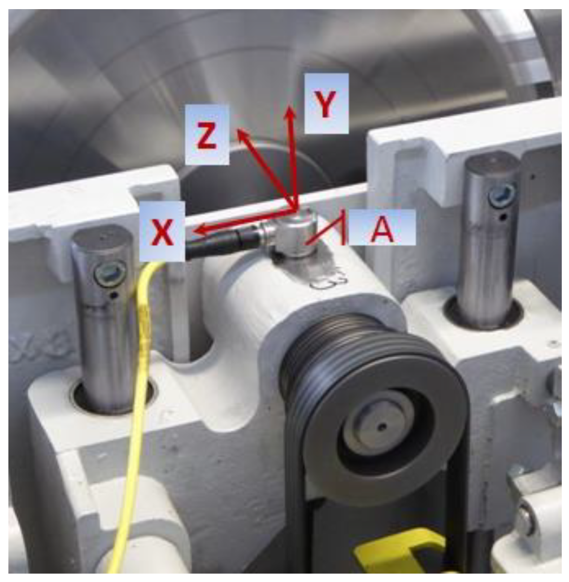
Vibration diagnostic experimental analyzes have been carried out on the saw cutting unit of the modernized table sliding saw Fx3 (currently Fx550) (f. REMA S.A., Reszel, Poland). The circular saw blade with main dimensions Ø300 × 3.2 × 30 and number of teeth z = 96 was mounted on the spindle with collars of Ø125 mm. The measured rotational speed of spindle was nwork = 5128 rpm. The place of the accelerometer (A in Figure 6) installation was also the measuring point position, and was located on the top of the main body of the spindle system. The Fluke 810 vibration tester (f. Fluke, Everett, Washington, DC, USA) was used to measuring of the accelerations in the X, Y, Z axes, which are axes of the machine tool co-ordination system (Figure 6).
The vibration tester Fluke 810 automatically converts the received acceleration signals into a waveform plot (Figure 7a) and creates vibration velocity spectra (Figure 7b). The latter feature is a disadvantage, since, the person conducting the tests has practically no influence on the way the test is performed, and the results are processed.
The changes of component velocities vj in function of time t, can be computed on the basis of vibrational velocity amplitudes (Figure 7b) [47]. The Root-Mean-Square (RMS) values of vibrational velocities were calculated for each measurement axis of the modernized table sliding saw Fx3. In the next step, the total vibrational velocity for the measurement point was computed from the equation as follows:
v Σ ( R M S ) = v X ( R M S ) 2 + v Y ( R M S ) 2 + v Z ( R M S ) 2 ,
Figure 8 presents RMS values of vibrational velocities in directions of X, Y and Z axes of the coordination system. In Figure 8, the value of the resultant RMS of vibrational velocity Sigma was also shown. The analyzed values in three directions X, Y and Z were measured at the measurement point (Figure 6).
Due to the use in literature the different criteria values for making an assessment of the new machine tool [32] in the analyzed investigation were determined two values: RMS amplitude of the total vibrational velocity and the peak value (amplitude). Obtained values from experimental test are presented in Table 1. Both Blake and Łączkowski are guided by the values of the peak amplitude [32]. However, for both standards, the experimental values obtained are evaluated differently (Table 1). A similar situation can be observed for the other two machine tool evaluation standards: own standards of the American diagnostic company, (IRD Machanalysis Limited, Maharashtra, India), and the British company VCI Ltd (Strabane, Great Britain). In this case, both standards base their assessment on the value of the RMS. Unfortunately, the evaluation of the examined main spindle system of the modernized table sliding saw Fx3 based on the experimental data received is again divergent for both standards (Table 1). The presented analysis shows that there are no unequivocal criteria for assessing the condition of the examined machine tool. Moreover, the choice of assessment criteria can very often be more or less subjective.

3.2. Dynamic Properties of the Machine Tool Body

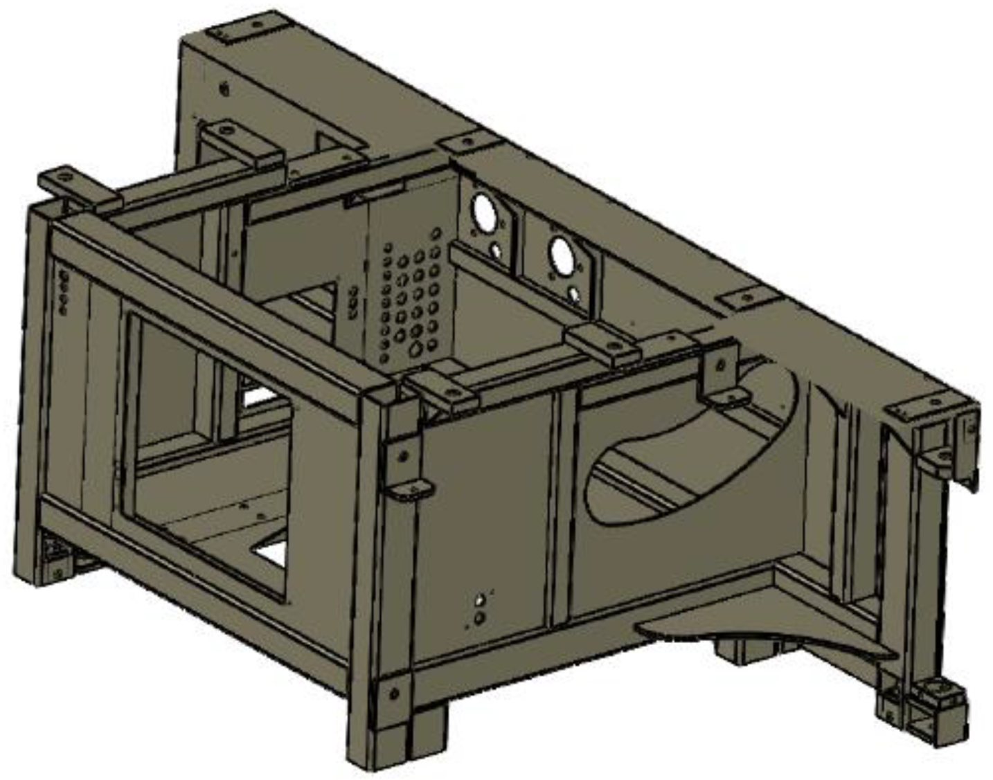
In the sliding table saw Fx550, which is the follower of the circular sawing machine Fx3, a new machine frame body made of steel sections connected with special lockers and welded was applied (Figure 9). In the previous version of the machine tool body, there was a solution which based on a set of bent body parts connected (mainly welded) with flat steel plates. The new design of the machine tool body has much more stiffness of the machine structure in comparison with the panel saw Fx3, and that kind of the body can be met only in the highest-class panel saws.
This body solution has given a spectacular reduction of the resultant peak values (amplitudes) vΣ of the vibrational velocities (Figure 10) measured at the point #4. The measurement point #4 was situated in each case in the middle on the body wall which was parallel to the main spindle axis. The value of the vibration velocity for the new solution is significantly below the permissible minimum value recommended by Łączkowski [32].
Testing the unloaded machine tools of both Fx3 and Fx550, maintaining tool setting, machining parameters were carried out in industrial conditions in the frame of the project POIR.01.01.01-00-05888/15 (in Polish Program Operacyjny Inteligentny Rozwój, Smart Growth Operational Programme). Measurements of noise were done with the use of the integrating sound level meter (SON-50) (f. Sonopan, Bialystok, Poland) in the points according to the International Organization for Standardization (ISO) standard (ISO 7960: 1995) [48]. At the location of the microphone in the operator position (about 1.5 m over the hall floor) for the sliding table saw Fx3 the noise on the idling was at the level of 77.5 dB whereas in case of Fx550 it was 73.5 dB. The resultant noise determined as an average from all measurement points was as follows: for Fx3 equalled to 79 dB and for Fx550 was equal 74.6 dB.
Thanks to: a new body of the sliding table saw Fx550, a modernized stiffer spindle, a stiffer system of the electric motor plate guiding [38], and a steady PK belt straining system the described sliding table saw Fx550 has been a source of the general noise on the idling at the level lower about 5 dB in comparison to the sliding table saw Fx3.

4. Conclusions

This review’s objective was to present a new holistic approach in the process of changing the sliding table saw design solutions in order to obtain a better machine tool that can compete in the contemporary machine tool market. Based on the review, it can be concluded that:
  • In modern design solutions of sliding table saws, the main circular saw blades are clamped by means of collars on spindles with a short support spacing with a ratio of the supports spacing L to the inner diameter of the front bearing d of about 3. It ought to be emphasized, that excessive increase in the diameter of the front bearing d and simultaneous striving for the optimum support spacing is not possible with the sliding table saws, as every manufacturer aims for the smallest possible dimensions of the cutting unit.
  • To evaluate the dynamic properties (behavior) of the spindle it is useful to determine their critical values of rotational speeds. The maximum deformations determined in static structural linear analyses showed that in the case of the Fx550 saw spindle they are 10× smaller in comparison with the spindle of the Fx3 saw, which made it possible to estimate critical speeds, which satisfied the inequality presented in Equation (2).
  • The use of only rational imitation in the spindle design on the basis of the other sliding table saws produced does not lead to the expected effect in the form of correct spindle operation, and this mainly concerns the possible exceeding of the tool’s lateral runout value.
  • The errors on sawn surfaces caused by the tool’s lateral runout value can be more apparent especially in case of top wood composite boards (MDF, HDF, LVL, plywood or particle boards) in the sawn package.
  • An application in a new machine frame body of steel sections connected with special lockers instead of the solution which based on a set of bent body parts between flat steel plates resulted in lower noise values of around 5 dB during idling.
  • If the noise of the machine tool is decreased and simultaneously vibrations are at lower level, hence, it could be expected higher accuracy of sawing which is especially important in furniture production.
  • Experimental values of vibrational velocities (RMS or peak value of vibrational velocities) on basis of a few diagnosis standards allowed us to classify the examined main spindle system of the sliding table saw Fx550 as good or admissible design solution from the point of its dynamics.

Author Contributions

Conceptualization, K.A.O., P.D. and W.B.; methodology, K.A.O., W.B. and D.C.; investigation, K.A.O., W.B., P.D., D.C. and T.P.; writing—original draft preparation, K.A.O., D.C.; writing—review and editing, K.A.O., D.C. and T.P.; supervision, K.A.O.; project administration, K.A.O. All authors have read and agreed to the published version of the manuscript.

Funding

It is kindly acknowledged that this work has been carried out within the framework of the project POIR.01.01.01-00-05888/15, which has been financially supported by the European Regional Development Fund. The authors would also like to acknowledge the company REMA S.A. in Reszel (Poland), which is the beneficiary of the project.

Acknowledgments

It should be acknowledged that the sliding table panel saw Fx550 has been awarded with the MTP Gold Medal of DREMA 2017 in Poznan, Poland. The role of Eng. Karol Duchnicz from Eaton Truck Components Sp. z o.o., ought to be acknowledged for his valuable guidance in spindle modelling.

Conflicts of Interest

The authors declare no conflict of interest.

References

  1. Goli, G.; Curti, R.; Marcon, B.; Scippa, A.; Campatelli, G.; Furferi, R.; Denaud, L. Specific cutting forces of isotropic and orthotropic engineered wood products by round shape machining. Materials 2018, 11, 2575. [Google Scholar] [CrossRef] [PubMed] [Green Version]
  2. Salca, E.-A.; Bekhta, P.; Seblii, Y. The effect of veneer densification temperature and wood species on the plywood properties made from alternate layers of densified and non-densified veneers. Forests 2020, 11, 700. [Google Scholar] [CrossRef]
  3. Mirski, R.; Derkowski, A.; Dziurka, D.; Dukarska, D.; Czarnecki, R. Effects of a chipboard structure on its physical and mechanical properties. Materials 2019, 12, 3777. [Google Scholar] [CrossRef] [PubMed] [Green Version]
  4. Hernandez-Vazquez, J.-M.; Garitaonandia, I.; Fernandes, M.H.; Muñoa, J.; López de Lacalle, L.N. A consistent procedure using response surface methodology to identify stiffness properties of connections in machine tools. Materials 2018, 11, 1220. [Google Scholar] [CrossRef] [Green Version]
  5. Orlowski, K.A.; Wasielewski, R. Study washboarding phenomenon in frame sawing machines. Holz als-Roh Werkst. 2006, 64, 37–44. [Google Scholar] [CrossRef]
  6. Mohammadpanah, A.; Hutton, S.G. Flutter instability speeds of guided splined disks. An experimental and analytical investigation. J. Shock Vib. 2015, 2015, 942141. [Google Scholar] [CrossRef] [Green Version]
  7. Mohammadpanah, A.; Hutton, S.G. Maximum operation speed of splined saws. Wood Mater. Sci. Eng. 2016, 11, 142–146. [Google Scholar] [CrossRef]
  8. Svoreň, J.; Hrčková, M. Woodworking Machines, Part I; Technical University in Zvolen: Zvolen, Slovak Republic, 2015. [Google Scholar]
  9. Mohammadpanah, A.; Hutton, S.G. Dynamic response of guided spline circular saws vs. collared circular saws, subjected to external loads. Wood Mater. Sci. Eng. 2019. [Google Scholar] [CrossRef]
  10. Hu, W.-Y.; Qi, Y.-J.; Zhang, Z.-H.; Qi, X.-J. Study on noise of precision panel saw. J. For. Res. 2003, 14, 335–338. [Google Scholar]
  11. Cempel, C. Diagnostyka Wibroakustyczna Maszyn; Politechnika Poznańska: Poznań, Poland, 1985. (In Polish) [Google Scholar]
  12. Szulewski, P.; Śniegulska-Grądzka, D. Systems of Automatic Vibration Monitoring in Machine Tools. Mechanik 2017, 90, 170–175. [Google Scholar] [CrossRef] [Green Version]
  13. Nasir, V.; Cool, J. A review on wood machining: Characterization, optimization, and monitoring of the sawing process. Wood Mater. Sci. Eng. 2020, 15, 1–16. [Google Scholar] [CrossRef]
  14. Kvietková, M.; Gaff, M.; Gašparík, M.; Kminiak, R.; Kriš, A. Effect of number of saw blade teeth on noise level and wear of blade edges during cutting of wood. Bioresources 2015, 10, 1657–1666. [Google Scholar] [CrossRef] [Green Version]
  15. Kminiak, R.; Gašparík, M.; Kvietková, M. The dependence of surface quality on tool wear of circular saw blades during transversal sawing of beech wood. Bioresources 2015, 10, 7123–7135. [Google Scholar] [CrossRef] [Green Version]
  16. Krilek, J.; Kováč, J.; Kučera, M. Wood crosscutting process analysis for circular saws. Bioresources 2014, 9, 1417–1429. [Google Scholar] [CrossRef]
  17. Hlásková, L.; Kopecký, Z.; Novák, V. Influence of wood modification on cutting force, specific cutting resistance and fracture parameters during the sawing process using circular sawing machine. Eur. J. Wood Wood Prod. 2020, 78, 1173–1182. [Google Scholar] [CrossRef]
  18. Mandic, M.; Svrzic, S.; Danon, G. The comparative analysis of two methods for the power consumption measurement in circular saw cutting of laminated particle board. Wood Res. 2015, 60, 125–136. [Google Scholar]
  19. Aguilera, A. Surface roughness evaluation in medium density fibreboard rip sawing. Eur. J. Wood Wood Prod. 2011, 69, 489–493. [Google Scholar] [CrossRef]
  20. Aguilera, A.; Barros, J.L. Surface roughness assessment on medium density fibreboard rip sawing using acoustic signals. Eur. J. Wood Wood Prod. 2012, 70, 369–372. [Google Scholar] [CrossRef]
  21. Barcenas, C.H.; Delclos, G.L.; El-Zein, R.; Tortolero-Luna, G.; Whitehead, L.W.; Spitz, M.R. Wood dust exposure is a potential risk factor for lung cancer. Am. J. Ind. Med. 2005, 47, 349–357. [Google Scholar] [CrossRef]
  22. Barański, J.; Jewartowski, M.; Wajs, J.; Orlowski, K.; Pikała, T. Experimental examination and modification of chip suction system in circular sawing machine. Drv. Ind. 2018, 69, 223–230. [Google Scholar] [CrossRef]
  23. Nasir, V.; Cool, J. Characterization, optimization, and acoustic emission monitoring of airborne dust emission during wood sawing. Int. J. Adv. Manuf. Technol. 2020, 109, 2365–2375. [Google Scholar] [CrossRef]
  24. Yokochi, H.; Nakashima, H.; Kimura, S. Vibration of circular saws during cutting I. Effect of slots on vibration. Mokuzai Gakkaishi 1993, 39, 1246–1252. [Google Scholar]
  25. Nishio, S.; Marui, E. Effect of slots on the lateral vibration of a circular saw blade during sawing. Mokuzai Gakkaishi 1995, 41, 722–730. [Google Scholar]
  26. Nishio, S. Stable sawblade. In Proceedings of the 17th International Wood Machining Seminar; Scholz, F., Ed.; Retru-Verlag e.K.: Weyarn, Germany, 2005; pp. 418–420. [Google Scholar]
  27. Droba, A.; Javorek, L.; Svoreň, J.; Pauliny, D. New design of circular saw blade body and its influence on critical rotational speed. Drewno 2015, 58, 147–157. [Google Scholar]
  28. Svoreň, J. The analysis of the effect of the number of teeth of the circular saw blade on the critical rotation speed. Acta Fac. Tech. (Zvolen–Slovakia) 2012, 17, 109–117. [Google Scholar]
  29. Orlowski, K.A.; Sandak, J.; Tanaka, C. The critical rotational speed of a circular saw: Simple measurement method and its practical implementations. J. Wood Sci. 2007, 53, 388–393. [Google Scholar] [CrossRef]
  30. Stakhiev, Y.M. Research on circular saws disc problems: Several of results. Holz als Roh-Werkst 2003, 61, 13–22. [Google Scholar] [CrossRef]
  31. Dietrych, J. System i konstrukcja, (In Polish, System and Design); Wydawnictwa Naukowo-Techniczne: Warszawa, Poland, 1978. [Google Scholar]
  32. Cempel, C. Vibroacoustic condition monitoring. In Ellis Horwood Series in Mechanical Engineering; Haddad, S.D., Ed.; Ellis Horwood Ltd.: New York, NY, USA, 1991. [Google Scholar]
  33. Wrotny, L.T. Projektowanie Obrabiarek. Zagadnienia Ogólne i Przykłady Obliczeń, (In Polish: Designing Machine Tools. General Issues and Examples of Calculations); Wydawnictwa Naukowo-Techniczne: Warszawa, Poland, 1986. [Google Scholar]
  34. Orlowski, K.A.; Duchnicz, K.; Dudek, P. Analiza wpływu cech konstrukcyjnych wrzeciona pilarki formatowej na jego obroty krytyczne. Mechanik 2016, 89, 1112–1113. [Google Scholar]
  35. Orlowski, K.A.; Dudek, P. Analysis of the design development of the sliding table saw spindles. Mechanik 2017, 90, 849–851. [Google Scholar] [CrossRef] [Green Version]
  36. Wasielewski, R.; Orlowski, K.A. The effect of the power transmission method of the spindle on the position of the circular saw teeth. In Proceedings of the 18th International Wood Machining Seminar, Vancouver, BC, Canada, 7–9 May 2007; pp. 97–103. [Google Scholar]
  37. Altendorf F45. Available online: https://www.altendorf.com/en/f-45.html (accessed on 20 October 2020).
  38. Pikała, T.; Rema, S.A., Reszel, Poland. Personal communication, 2017.
  39. Rema Fx550. Available online: https://rema-sa.pl/produkty/pilarka-formatowa-rema-fx550 (accessed on 27 August 2020).
  40. UNICA 400 and UNICA 500. Available online: https://wtp.hoechsmann.com/en/lexikon/20024/unica_500 (accessed on 20 October 2020).
  41. K 700 S. Available online: https://www.felder-group.com/pl-pl/produkty/pily-formatowe-c1947/pila-formatowa-k-700-s-p64674 (accessed on 11 September 2020).
  42. PF 400S. Available online: http://rojek.cz/pdf/PF300L_350_400S_New.pdf (accessed on 11 September 2020).
  43. Černoch, S. Strojnĕ Technická Přiručka 1; SNTL-Státní nakladatelství technické literatury: Praha, Czechoslovakia, 1968. [Google Scholar]
  44. SKF Belt Calculator. Available online: https://www.skfptp.com/Publications/Publications# (accessed on 11 September 2020).
  45. SKF. Available online: https://www.skf.com/my/products/super-precision-bearings/principles/bearing-selection-process/bearing-execution/system-rigidity (accessed on 2 September 2020).
  46. Orlowski, K.; Duchnicz, K. The effect of a belt position in the spindle driving system on critical rotational speeds. Ann. WULS-SGGW For. Wood Technol. 2016, 95, 303–307. [Google Scholar]
  47. Orlowski, K.A.; Blacharski, W.; Pikała, T. Empirical assessment of the main driving system of the circular sawing machine. Trieskove Beztrieskove Obrabanie Dreva 2016, 10, 145–151. [Google Scholar]
  48. ISO-7960: Airborne Noise Emitted by Machine Tools—Operating Conditions for Woodworking Machines; ISO: Geneva, Switzerland, 1995.
Figure 1. Quality indices of the machine tool and their relation to vibrations, where: MPC—machining process conditions; Q1, Q2, Q3, Q4—quality indices.
Applsci 10 07386 g001
Figure 2. Long main spindle in the sliding table saw DMMS-40 Classic (a, REMA S.A.) and short main spindle (a) view from motor side in the sliding table saw Fx550 (b), REMA S.A.
Applsci 10 07386 g002
Figure 3. The resultant deformation (in mm) of the spindle in the table sliding saw Fx3 caused by the cutting forces and by the force Fs-d, for the operating speed nwork = 3500 min−1.
Applsci 10 07386 g003
Figure 4. The resultant deformation (in mm) of the spindle in the Fx550 sawing machine caused by the cutting forces and by the force Fs-d, for the operating speed nwork = 3500 min−1.
Applsci 10 07386 g004
Figure 5. Ratios of critical rotational speeds to working rotational speeds revolutions ncr/nwork of spindles of table sliding saws Fx3 (an old applied solution) and Fx550 (a currently applied design) (Rema SA), where vertical bold lines indicate the limits of the recommended values of the ratio ncr/nwork.
Applsci 10 07386 g005
Figure 6. A view of the saw cutting unit of the modernized table sliding saw Fx3 with a position of the accelerometer A, where: X, Y, Z—axes of the table sliding saw co-ordination system [47].
Applsci 10 07386 g006
Figure 7. Waveform of the acceleration signal (a) and vibrational velocity spectrum of the signal (b) of the modernized table sliding saw Fx3 in the measurement point (Figure 6) in Z axis [47].
Applsci 10 07386 g007
Figure 8. Root-mean-square values of vibrational velocities in directions of X, Y and Z axes of the modernized table sliding saw Fx3 co-ordination system measured at the measurement point (Figure 2a) together with a resultant Root-Mean-Square RMS of vibrational velocity Sigma.
Applsci 10 07386 g008
Figure 9. General view of the frame body of the sliding table saw Fx550.
Applsci 10 07386 g009
Figure 10. Resultant peak values (amplitudes) of the vibrational velocities vΣ measured on the frame body at the measurement point #4 of the sliding table saws Fx3 and Fx550.
Applsci 10 07386 g010
Table 1. Experimental values of vibrational velocities with diagnostic evaluation on basis of a few diagnosis standards.
RMS of Vibrational Velocities, vΣ
mm·s−1
Peak Value of Vibrational Velocities, vmax
mm·s−1
Experimental Results2.083.27
StandardsDiagnosisRange RMS of vibrational velocities for diagnosis, mm·s−1
or
*range peak value of vibrational velocities, mm·s−1
IRD MechanalysisAdmissible2–4
VCI Ltd.Good1.27–2.54
BlakeAdmissible*2.20–6.00
ŁączkowskiGood*2.50–6.30
Publisher’s Note: MDPI stays neutral with regard to jurisdictional claims in published maps and institutional affiliations.