Article

Teleoperation Control Design with Virtual Force Feedback for the Cable-Driven Hyper-Redundant Continuum Manipulator

1
Ocean College, Zhejiang University, Zhoushan 316021, China
2
The State Key Laboratory of Fluid Power and Mechatronic Systems, Zhejiang University, Hangzhou 310027, China
3
Zhejiang Lab, Hangzhou 311100, China
*
Author to whom correspondence should be addressed.
Appl. Sci. 2020, 10(22), 8031; https://doi.org/10.3390/app10228031
Submission received: 26 October 2020 / Revised: 9 November 2020 / Accepted: 10 November 2020 / Published: 12 November 2020
(This article belongs to the Section Robotics and Automation)

Abstract

:
Hyper-redundant continuum manipulators present dexterous kinematic skills in complicated tasks and demonstrate promising potential in underground exploration, intra-cavity inspection, surgery, etc. However, the hyper-redundancy, which endows much dexterity and flexibility, brings a huge challenge to the kinematics solution and control of the continuum manipulators. Due to the pseudoinverse calculation of high-order Jacobian matrix or iteration, many inverse kinematic solution approaches of continuum manipulators are very time-consuming, which extremely limit their applicability in real-time control. Additionally, it is often difficult for the manipulators to perform the tasks well in complex scenarios due to lack of human intervention. Therefore, in this paper, a simplified kinematics model of a typical hyper-redundant manipulator is proposed based on its unique geometry relationships, where the mapping relationships between the actuators’ rotation and the end-effector’s position are derived through the analysis of its driving subsystem and motion subsystem, in particular the joint modules. To perform the tasks of manipulators with the help of operators, a teleoperation control scheme with modified wave transmission structure is designed to achieve the guaranteed stability and improved transparency, and the leader’s trajectory and generated force feedback are the transmitted signals in the communication channel. Specifically, a virtual force feedback generation algorithm is developed in the teleoperation control scheme via the processing tracking errors, which can improve the operators’ assistance and perception during the teleoperation process. The practical experiments with comparative wave variable structures in two different sets are implemented to verify the effectiveness of proposed kinematics model and control scheme.

1. Introduction

Traditional robots with a fixed degree of freedom (DOF) have been primarily devised for repetitive industrial production tasks in known and structured environments with little human participation [1]. With the increasing demand for complicated exploration or operation tasks in complex scenarios, hyper-redundant continuum manipulators, which exhibit more dexterity and flexibility during motion [2,3], have attracted much attention of researchers. Among them, inspired by the concept of biomimetic muscles and tendons, such as the snake or octopus, cable-driven hyper-redundant continuum manipulators (CHCM) or similar designs generally consist of multiple serially connected joint modules driven by cables, rigid linkages or elastic materials [4,5]. Due to the redundant DOFs, CHCM can reach desired positions with different postures; thus, flexible motion, good obstacle avoidance capability, and security can be achieved for surgery, ocean exploration, underground or intra-cavity inspection etc. [6].
Various mechanical designs of continuum manipulators with different actuator and connection structures have been developed [7], where the complexity of kinematics and the control method caused by complicated and per-redundant relationships between cables, joints and end-effector positions are the key problem to be solved [8,9].
The first snake-like continuum robot was designed about 50 years ag. Since then, research about continuum robots has been emerging in large numbers [10]. Choset et al. [11,12] proposed a serious of different modular continuum robots and corresponding control methods to achieve reliable movement in complicated terrains. In particular, the Unified Snake robot was designed with up to 16 joints and presented a variety of motion patterns and excellent obstacle avoidance ability [13,14]. A continuum robot consisting of several same joints was developed by Mamba and the attached force/torque sensors provide the information of how the robot touches surrounding environments [15]. Buckingham, et al. of OC Robotics [5] developed a commercialized CHCM suitable for assembly tasks within wing boxes and replacing manual procedures, where a complex kinematics model was established to deal with the strong nonlinearity. Zhao Zhang [16] proposed a cable-driven snake-like robot consisting of 2-DOF joint modules with a flexible backbone, then an instantaneous kinematic model and numerical inverse kinematics (IK) algorithm were derived, which is solved via Newton–Raphson method. Another commonly used method for IK questions is solving the pseudoinverse of the Jacobian matrix, based on which a multi-section continuum robot was designed and its kinematics model with optimized motion trail among cable displacements and joint rotations was derived [17,18,19]. To cope with the challenge of solving IK for hyper-redundant robots, a modified computing method was proposed to solve IK of ( 2 n + 1 ) DOF continuum manipulator, where the analytical approach was adopted to improve the efficiency of solvers on each joint and the IK question was handled as an optimization problem [20]. For achieving the best result of multi-solution IK problems for hyper-redundant robots, a computing algorithm based on the cyclic coordinate descent was presented, which could handle many redundant DOFs in three spatial dimensions [21]. M.S. Espinoza et al. [22] compared an exhaustive method and several optimization algorithms considering computing time-cost and tolerable position error, where the limitations of each method were explained.
Based on mechanical designs and kinematics or dynamic modeling, upper-level control strategies through optimization or model-free approaches have become another important research mission, such as the attitude control, obstacle avoidance and adaptive tracking [21,23]. To perform complex tasks in remote scenarios with dexterous kinematic skills, the teleoperation technique is introduced as the control strategy for manipulators, where the operator moves the leader robot and generates the desired trajectory signals and transmits to the follower through commination channel [24,25,26]. Barrio et al. proposed a control strategy for teleoperating the designed hyper-redundant robot in a hazardous environment with mixed reality and immersive technology, thus the operator could command the robot and observe a reconstructed environment via a head-mounted display in a remote location [27]. Ren et al. designed a real-time control leader-salve teleoperation for a snake robot and the kinematics problem was handled via the Monte Carlo method and optimization algorithm [28]. In the research of Berthet-Rayne [29], a teleoperation system for redundant snake-like surgery robots comprised of 26 joint variables was developed, and 6 different control methods were compared including Jacobian, iterative and linear programming methods. Though some teleoperation systems of CHCM have been proposed in the research mentioned above, the communication time delay between leader and follower robot, which may cause instability and poorer performance [30,31], and the force feedback has not been taken into consideration generally. Therefore, to deal with these hostile factors, the wave variable method was developed to guarantee the stability of the teleoperation system, which could be guaranteed theoretically based on the passivity and scattering-based theories [32]. In the earlier research about wave variable methods, the system stability can be ensured [33,34], but the transparency including trajectory tracking and force feedback performance is distorted because of the bias term in transmitted wave variable signals [30]. Afterwards, modified wave variable-based teleoperation structures have been proposed to improve the system transparency with guaranteed stability [35]. Bate et al. presented a new wave transformation method to reduce the bias term caused by wave reflections, thus the velocity tracking and force feedback performance was improved in unknown working environments [36]. Ye et al. proposed corresponding methods to satisfy different requirements of performance, for example an augmented forward wave was generated via the perceived force and follower control force to improve the trajectory tracking performance; a method helping reduce the bias term was partially adopted to enhance the fidelity of haptic feedback [37,38]. However, the simultaneously good position-tracking and force feedback performance of teleoperation system is still challenging, especially for CHCM.
In this paper, a design of CHCM for complicated tasks, which adopts a structure of separating driving subsystem and motion subsystem, is introduced and it has redundant DOFs due to the abundant numbers of joint modules. According to the system geometry structure of CHCM, the simplified forward and inverse kinematics model for real-time control is established based on some assumptions of the CHCM’s motion characteristics, which avoids time-cost pseudoinverse computation of the Jacobian matrix. To achieve operator assistance and perception, a modified teleoperation control scheme is introduced for the upper-level control of CHCM with guaranteed stability and improved transparency, where a 2-DOF Cartesian working space mapping method and a virtual force feedback generation algorithm are presented. The performance of the proposed system is theoretically proved via scattering theory and experimentally indicated through a series of comparative experiments.
The remaining part of this paper is organized as follows: the general structure and kinematics model of CHCM is introduced in Section 2. In Section 3, a modified wave variable-based teleoperation scheme with virtual force feedback generation is proposed, and the stability and transparency are analyzed. In Section 4, a series of comparative experiments is carried out and the results show the efficiency of derived kinematics model and proposed control scheme. Finally, the main work of this paper is concluded in Section 5.

2. Configuration and Kinematics Modeling

2.1. General Structure of CHCM

The proposed CHCM adopts a structure of separating the driving subsystem and motion subsystem, as shown in Figure 1. The manipulator, namely the motion subsystem, contains multiple cable-driven joint modules serially connected with adjacent ones by a universal joint. Each joint module comprises a tubular structure and two fixed endplates used to link the tubular structure with universal joints, as shown in Figure 2b. The three driving cables of each joint are equally spaced at 120 and attached to the rear endplate, through holes in the circumferential directions pierced in tubular structures and endplates. With the cables, the rear endplate of every joint module is connected to the driving subsystem, in which the driving cables are controlled by the actuators. The rotation of actuators is converted to the horizontal linear motion of connecting plates via reducers, leading screws, sliders etc., which are fixed to screw nut seats and the cables are attached to, as shown in Figure 2a. To measure length changes of these driving cables, the linear magnetic encoders are adopted, ignoring the deformation of the cables. As a result, the joint module will present 2-DOF rotational motions with the contraction of the driving cables, namely the rotation of the actuators.

2.2. Forward and Inverse Kinematics Based on Geometrical Relationships

According to the structure of CHCM, the 3-DOF position of end-effector is determined by the deflection of every 2-DOF joint module, which can be described by two parameters: rotation about X-axis by angle φ and rotation about Z-axis by angle θ . The world coordinate system W o is defined, with its origin at the center of the base plate and y axis perpendicular to the base plate and pointing to the end-effector, as shown in Figure 3.
The purpose of forward kinematics analysis is to determine every joint angle and then compute the end-effector position when the lengths of three driving cables are given. Correspondingly, the inverse kinematics model is supposed to calculate the expected joint angles and cable lengths with given end-effector positions.

2.2.1. Kinematics between Cable Lengths and Joint Angles

To establish the kinematics model between cable lengths and joint angles, a geometric model is presented as shown in Figure 4, noting that adjacent universal joints are orthogonal rather than in the same direction, although the same model is adopted, which does not impact the outcome. To be simplified, a coordinate system is created. Frame P i and R i are attached to the proximal endplate and rear endplate of ith tubular structure with their origins located at the centers of those plates, respectively.
When joint angles Φ i = [ φ i , θ i ] i = 1 , 2 , , N are given, the three driving cables of ith joint will present unique and definite lengths L i , j ( j = 1 , 2 , 3 ) , where N represents the number of all joints. Similarly, some essential symbols, their properties, and corresponding values of CHCM are presented in Table 1.
According to the principle of the coordinate system transformation, the pose transformation matrix of joint frame P i with respect to adjoining one R i 1 connected by one universal joint could be expressed as:
T i 1 i = T r a n s ( 0 , D , 0 ) R o t ( Z , θ i ) R o t ( X , φ i ) T r a n s ( 0 , D , 0 )
where T r a n s ( 0 , D , 0 ) represents the translation function, which can be written as:
T r a n s ( 0 , D , 0 ) = 1 0 0 0 0 1 0 D 0 0 1 0 0 0 0 1
and R o t ( Z , θ i ) , R o t ( X , φ i ) represent the rotation function about X-axis by angle φ i and rotation about Z-axis by angle θ i , respectively, which can be written as:
R o t ( Z , θ i ) = cos θ i sin θ i 0 0 sin θ i cos θ i 0 0 0 0 1 0 0 0 0 1 , R o t ( X , φ i ) = 1 0 0 0 0 cos φ i sin φ i 0 0 sin φ i cos φ i 0 0 0 0 1
As shown in Figure 3, α i , j is a counterclockwise angle, which represents the deflection angle of the attachment point of jth cable on the ith tubular structure and X-axis of P i , which can be derived as (4). Such that the attachment position p i , j and the cable length between p i , j and p i 1 , j can be derived as (5) and (6).
α i , j = i · 360 M + ( j 1 ) · 120
p i , j = [ R · cos α , 0 , R · sin α ] T
l i , j = T i 1 i · p i , j p i , j
Ignoring the deformation of cables and considering that the cables in every tubular structure get lengths of H, the total lengths of cables can be derived as:
L k , j = i k ( l i , j + H )
When cable lengths L i , j ( j = 1 , 2 , 3 ) are given, each joint angle will be unique and definite, which can be solved from Equation (8).
l i , j = T i 1 i · p i , j p i 1 , j = f ( θ i , φ i , α i , j )

2.2.2. Kinematics between Joint Angles and End-Effector Position

Based on the coordinate system in the last section, the forward kinematics model from joint angles to end-effector position could be easily derived, similarly via coordinate transformation. The transform matrix from the world coordinate system W 0 to the end-effector frame R N could be derived as:
T W N = i = 1 N ( T i 1 i · T r a n s ( 0 , H , 0 ) )
where T i 1 i is defined by Equation (1) and the definition of T r a n s ( 0 , H , 0 ) is similar to Equation (2).
Due to the high redundancy of CHCM, the analytic solution of inverse kinematics does not exist and the numerical methods usually spend tremendous amounts of computational time based on the pseudoinverse of the Jacobian matrix. To improve the real-time performance of inverse kinematics computing, an efficient solution method based on geometric relationship of CHCM and some assumptions of its motion feature is introduced in this section.
In confined working scenarios, the motion of the manipulator is restricted by both environment and mechanical structure, which means the joint modules are supposed to move less within a maximum limited angle. Thus, to simplify, some assumptions of the manipulator’s motion are proposed.
  • The position of the end-effector is mainly in an optional plane P T Y perpendicular to the Y-axis.
  • The last tubular structure is parallel to the Y-axis.
  • The movement of the end-effector in the Y-axis direction is achieved by selecting different optional planes.
To simplify the analysis, the joints are represented by dots and the tubular structures are represented by lines with a length of L = H + 2 · D , as shown in Figure 4. Suppose that the proximal end point of ith line is at A i ( x i , y i , z i ) ( i = 1 , 2 , , N ) , and the position of end-effector is A N + 1 ( x N + 1 , y N + 1 , z N + 1 ) , whose relationship could be derived as Equation (10).
x n + 1 = x n y n + 1 = y n + L z n + 1 = z n
To calculate the desired position of each joint, a reference pose of CHCM is created where φ 1 = χ , θ 1 = 0 and φ i = 0 , θ i = 0 ( i = 2 , , N 3 ) , thus, the equation of P T Y is y = ( N 1 ) · L · cos ( χ ) + L . The subscripts r and d denote reference pose and desired pose, respectively. When the proximal end point of Nth line A N , d ( x N , d , y N , d , z N , d ) is determined by Equation (11), the movement of last N k + 1 joint modules could achieve the desired position of the end-effector.
A N , d A k + 1 , r ( N k 1 ) · L A N , d A k , r ( N k ) · L
As shown in Figure 5, the points A i , d ( i = k + 1 , N ) in this state are located on a straight line; specifically, the angles φ i , d , θ i , d ( i = k + 2 , N 1 ) stay zero. Then, according to the system geometry structure, the end point of ( k + 1 )th line A k + 1 , d satisfies Equation (12).
A k , d A k + 1 , d = L A k + 1 , d A N , d = ( N k 1 ) · L
As the end-effector moves in P T Y , we select the more accessible intersection point of the circle determined by Equation (11) and a fixed plane as the coordinate of A k + 1 , d , which is defined by A 1 , r , A n 2 , r A n , r and expressed as Equation (12). Thus, A k + 1 , d also satisfies Equation (13).
f ( A ( x , y , z ) ) = a · x + b · y + z = 0
Since A k + 1 , d and A N , d are known, the coordinates of other joint modules can be calculated. The directional vector of each tubular structure in the world coordinate system W 0 could be transformed from the adjacent one by rotation functions, which is written as Equation (14) or (15) due to the direction of universal joint. Then, joint angles Φ i = [ φ i , θ i ] i = 1 , 2 , , N can be solved.
A i + 1 , d A i , d = R o t ( Z , θ i ) · R o t ( X , φ i ) A i , d A i 1 , d ( i = 2 , 3 , , N )
A i + 1 , d A i , d = R o t ( X , φ i ) · R o t ( Z , θ i ) A i , d A i 1 , d ( i = 2 , 3 , , N )
Thus, Equations (9) and (13) or Equation (14) present the forward and inverse kinematics model between joint angles and end-effector position.

3. Teleoperation Control Design with Wave Variable and Virtual Force Feedback

3.1. Modified Wave Variable Architecture

In a wave variable-based teleoperation control scheme, the leader robot sends desired motion information to the follower manipulator and receives force feedback conversely through communication modules, where the wave variable method is adopted to deal with inherent system time delay and guarantee the passivity, namely the stability of the teleoperation system at the cost of insufficient transparency including position-tracking and force feedback. Therefore, a design of modified wave variable architecture is proposed in this section inspired by the bilateral teleoperation schemes in [36], as shown in Figure 6, where X ˙ m and X ˙ s are the velocities of leader and follower; F m and F s denote the forces of leader and follower; X ˙ s d represents the desired velocity of the follower. To improve the system transparency, two transform parameters are introduced, among which the impedance parameter b is used for position-tracking performance and the gain coefficient K reduces force feedback error. Furthermore, a first-order low-pass filter expressed as λ / ( s + λ ) is adopted in the forward communication channel to eliminate high-frequency noise of velocity caused by manual operation and ensure the system passivity by dissipating inherit energy [33].
In the proposed architecture, the transformed wave variables transmitted in the communication channel can be derived as:
u m ( t ) = b · X ˙ m ( t ) + F s ( t T ) K L 1 ( λ s + λ )
v s ( t ) = F s ( t ) K
where T is the constant time delay in communication channel between the leader and follower, ⊗ and L 1 represent convolution and inverse Laplace transform, respectively.
According to the architecture shown in Figure 6, the received desired velocity in follower X ˙ s d and force feedback F m in leader can be written as:
X ˙ s d ( t ) = K · u m ( t T ) b F s ( t ) b
F m ( t ) = K · v s ( t T ) + K · b · X ˙ m ( t )
Hence, by substituting Equations (15) and (16) into Equations (17) and (18), the transmission relationships between the leader and follower could be derived as:
X ˙ s d ( t ) = X ˙ m ( t T ) L 1 ( λ s + λ ) + 1 b · ( F s ( t 2 · T ) L 1 ( λ s + λ ) F s ( t ) )
F m ( t ) = F s ( t T ) + K · b · X ˙ m ( t )

3.2. Virtual Force Feedback Generation and Controller Design

To realize the teleoperation control from leader to follower, namely the CHCM, considering the assumptions and irregular accessible range of the manipulator’s motion, a 2-DOF Cartesian working space mapping method is proposed in this section. The motion of selected leader robot, Phantom Omni device, in X O Y plane is transformed to desired position of follower in P T Y plane, which can be written as:
x s d y s d z s d = k x 0 0 0 0 0 0 k y 0 x m y m z m + 0 y 0 0
where k x , k y are scare factors and y 0 is the y coordinate of P T Y plane.
To achieve the operator’s perception of follower’s motion state, a virtual force feedback generation algorithm is presented based on some presuppositions of working space and the position of leader and follower, which can be derived as:
F s = F e X s X u F e + F b o t h e r s
F e = k f · ( 1 1 + e X s d X s 0.5 )
F b = k b · ( X b X s ) + c b · X ˙ s · N
where k f is the primary parameter to adjust the amplitude of virtual force during free motion; k b and c b are the spring modulus and damping coefficient of environment exceeding presupposed accessible unconstrained location X u , which is regarded as a spring-damper. X b represents the boundary of X u and N denotes the unit normal vector of contact position of the follower and X b pointing to X u . Remarkably, the parameters k b and c b are defined based on presupposed virtual boundary or known prior information about real environment and take values only when the position of follower X s reaches or exceeds the setting boundary X b .
As expressed in Equations (23)–(25), the generated virtual force F s changes continuously and boundedly with tracking errors X s d X s and presents more sensitivity with small tracking errors. Hence, the virtual force feedback can provide operators with the perception of tracking errors, and motion state of follower relative to the boundary X b .
Based on the structures of CHCM, a teleoperation control scheme is proposed to achieve good tracking performance of follower, as shown in Figure 7. According to the inverse kinematics model of CHCM, the desired position X s d is transformed to desired lengths L d of driving cables of each joint module. By measuring the actual lengths of driving cables L s with linear magnetic encoders, a closed-loop PID controller is designed as Equation (26) to realize accurate cable length control.
u = K P · ( L d L s ) + K I · 0 t ( L d L s ) d τ + K D · ( L ˙ d L ˙ s )
where K P , K I , K D are parameters of the PID controller, and the output of controller u determines the rotation speed of each actuator.
Meanwhile, the virtual force F s transmitted from the follower and the velocity of leader X ˙ m generate the feedback force F m on the leader. Hence, the dynamics of the leader robot can be expressed as Equation (27), considering the leader as a particle with a mass of M m .
F h ( t ) F m ( t ) = M m · X ¨ m ( t ) , X ˙ m ( t ) = F h / Z h
where F h is the control force exerted by the operator and Z h is the operator impedance coefficient.

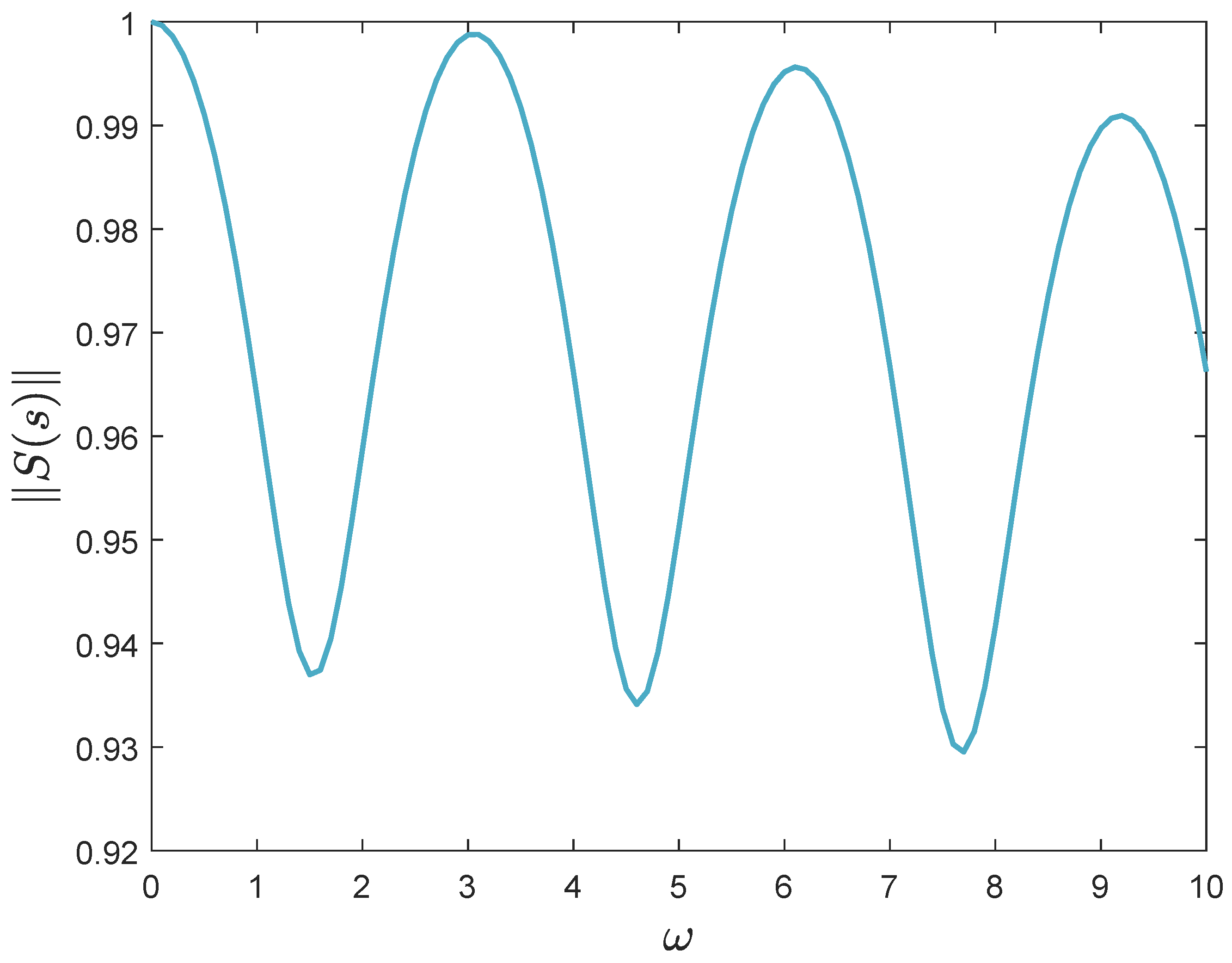
3.3. Stability and Transparency Analysis

A sufficient condition to prove the stability of teleoperation systems with time delays is that the adopted wave variable-based communication architecture is passive, for the leader and follower with PID controllers are passive [30]. According to the scattering operator theory, the passivity of teleoperation system can be guaranteed if and only if its scattering operator S ( s ) satisfies:
S ( s ) 1
where the scattering operator S ( s ) is defined by:
S ( s ) = 1 0 0 1 H ( s ) I H ( s ) + I 1
where the hybrid matrix of the proposed teleoperation scheme can be defined by Equation (29) and derived from Equations (20) and (21) as Equation (31).
F m ( s ) X ˙ s ( s ) = H ( s ) · X ˙ m ( s ) F s ( s )
H ( s ) = K · b e s T e s T · λ s + λ 1 b e 2 s T b · λ s + λ
As implied by Formulas (29) and (31), when s is defined as j ω , the function e j ω T will have a periodic impact on the norm of S ( s ) with a constant time delay T, which means T does not exert extra influence but on the angular frequency of S ( s ) among ω axis. The parameters K and b to be designed affect the passivity of teleoperation system largely, of which the values are limited to 0 , 1 and 1 , + , respectively, considering the influences on the tracking performance and force feedback with regard to Equations (20) and (21). By the iteration of different parameters in MATLAB, it is illustrated that S ( s ) is always no more than one with K 0.5 , 1 .
The simulation result, as shown in Figure 8, preferably indicates that the scattering matrix norm of proposed teleoperation scheme will remain not greater than one with obvious periodical characteristic, and the one-order low-pass in the communication channel enhances the system passivity by reducing the norm of S ( s ) with increasing frequency, where K = 0.6 , b = 10 , T = 1 , λ = 20 .
With guaranteed passivity, the transparency of the proposed teleoperation system is also improved regarding Equations (20) and (21). Concretely, the virtual force F s will present slight and small change according to Equations (23) and (24) when the tracking error X s d X s is almost time invariant or smoothly varying; therefore, the transformed desired velocity X ˙ s d of follower accurately reaches or gets close to the desired value with the filter eliminating noise of wave variables. With move-and-wait operation strategy adopted [39], the operator will have an exact perception of virtual force via stopping the leader, since F m ( t ) is exactly equal to the virtual force F s ( t T ) when X ˙ m ( t ) = 0 . Furthermore, a larger value is chosen for b when F s shows rapid changes to suppress the distortion of X ˙ s d . However, the parameter b has a reverse effect on force feedback and increases the force feedback error according to Equation (21), to cope with which the secondary parameter K is introduced with a small value. Thus, a good system transparency including good position-tracking performance and force feedback can be obtained simultaneously in the proposed teleoperation scheme with appropriate values of b and K.

4. Experiment

In this section, a series of comparative experiments are conducted for the following purpose.
  • To demonstrate that the derived forward and inverse kinematics of CHCM based on geometrical relationships are validated and applicable for CHCM due to its real-time performance.
  • To illustrate that the teleoperation system of CHCM remains stable with time delays and shows better transparency adopting the proposed teleoperation control scheme including wave variable architecture and virtual force feedback generation method.

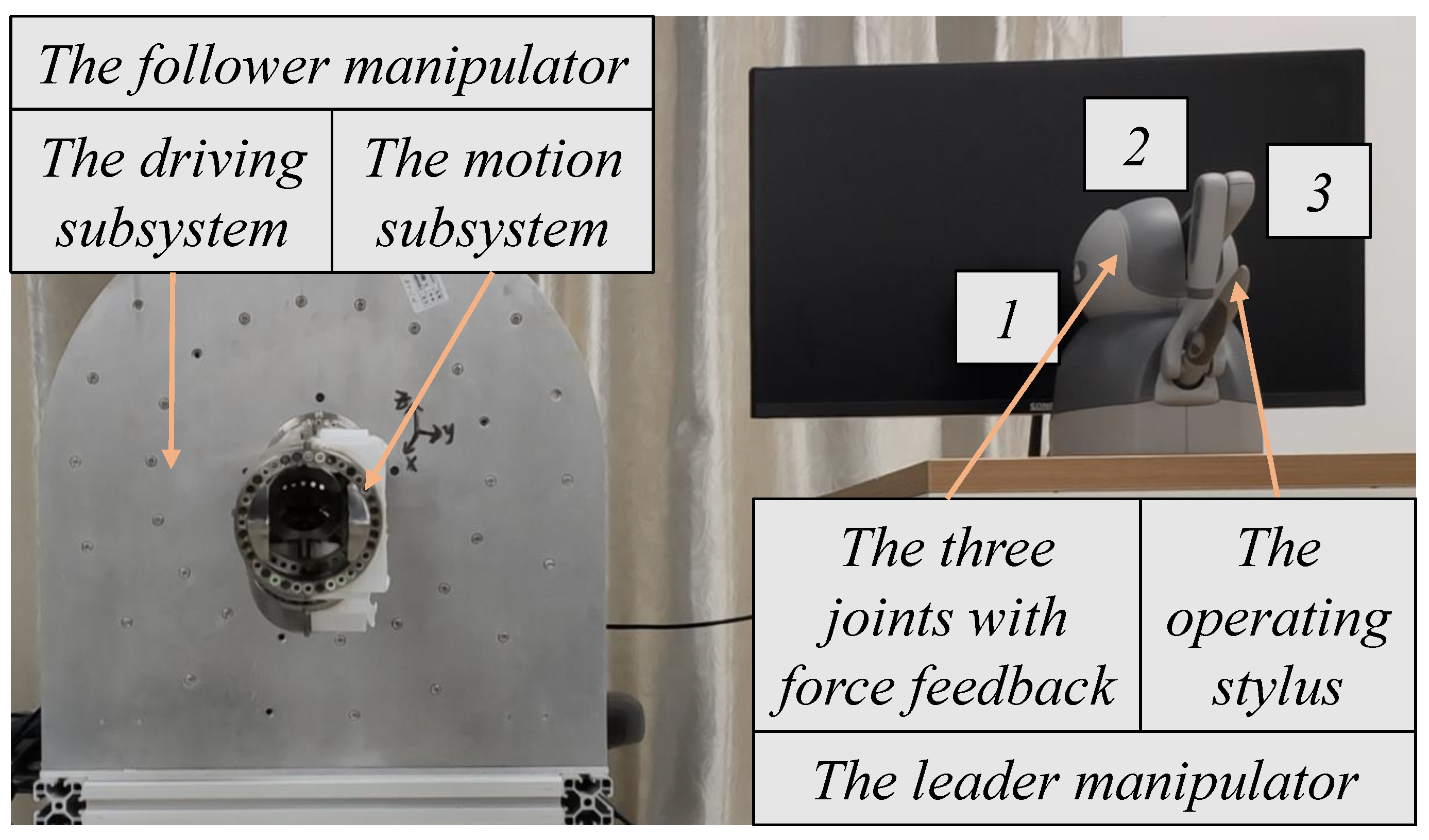
4.1. Experiment Platform

The experiments are implemented on the 3D Systems Touch device and CHCM connected by a real-time platform via the MATLAB/Simulink and QUARC, which represent the leader and follower robot respectively, as shown in Figure 9. The experiments are implemented via the leader and follower robots and a control platform composed of the MATLAB/Simulink and QUARC, a real-time control software made by Quanser. The follower robot, namely the CHCM introduced in the previous sections, is supposed to track the motion trajectory of leader. In addition, the leader robot is a commercially available haptic device named Touch made by 3D Systems, which could provide accurate position input and force feedback output and is a good choice for our experiment platform. The whole experiment platform is shown in Figure 9. The stylus of Touch generates desired motion trajectory with human operation and produces perceptible force feedback at 1 kHz. The desired trajectory is transmitted to the follower robot through the wave variable-based communication channel, and the commands generated by PID controller are sent to corresponding actuators through Quanser data acquisition card at 1 kHz. Specifically, some devices and software are listed in Table 2.

4.2. Experiment Setup

To verify the effectiveness of the proposed control scheme in this paper, two teleoperation schemes C1 and C2 were compared in two designed situation sets, Set1 and Set2. More concretely, a relatively new control method presented in [36] is experimentally compared, where all the experimental conditions and common parameters are the same to have a fair comparison. The different two control schemes are described as follows:
C1. The original wave variable-based control design reducing reflections proposed by in [36], where b = 10 and the constant time delay is set as T = 0.2 . In addition, the parameters of PID controller are selected as K P = 5 , K I = 2 , K D = 0.05 to achieve rapid and stable response of each actuator.
C2. The modified wave variable-based control scheme proposed in this paper to guarantee the position-tracking performance and improve the transparency of force feedback, where b, T and PID controller remain the same with C1 and the secondary parameter K is selected as a small value with K = 0.5 . Moreover, considering the frequency of desired trajectory, the parameter of low-pass filter is set as λ = 20 .
As illustrated by Equation (23), to provide operators with the perception of tracking errors and constrained location, a virtual force feedback is generated during the whole moving phase. Thus, two different situation sets are designed to show the transparency performance of the proposed control scheme in free or constrained motion space as follows:
Set1. The experiments into trajectory tracking in free motion space are carried out to show the accurate kinematics control of CHCM and the improvement of force feedback transparency adopting control scheme C2. During free motion, the parameter of force feedback k f is set as k f = 3 .
Set2. The experiments into trajectory tracking when reaching and released from the constrained space are carried out to show the rapid change of virtual force feedback with guaranteed tracking performance, which could reflect the influence of constrained space. The spring modulus and damping coefficient of the environment are set as k b = 0.5 , and c b = 1 respectively when CHCM reaches the setting boundary.

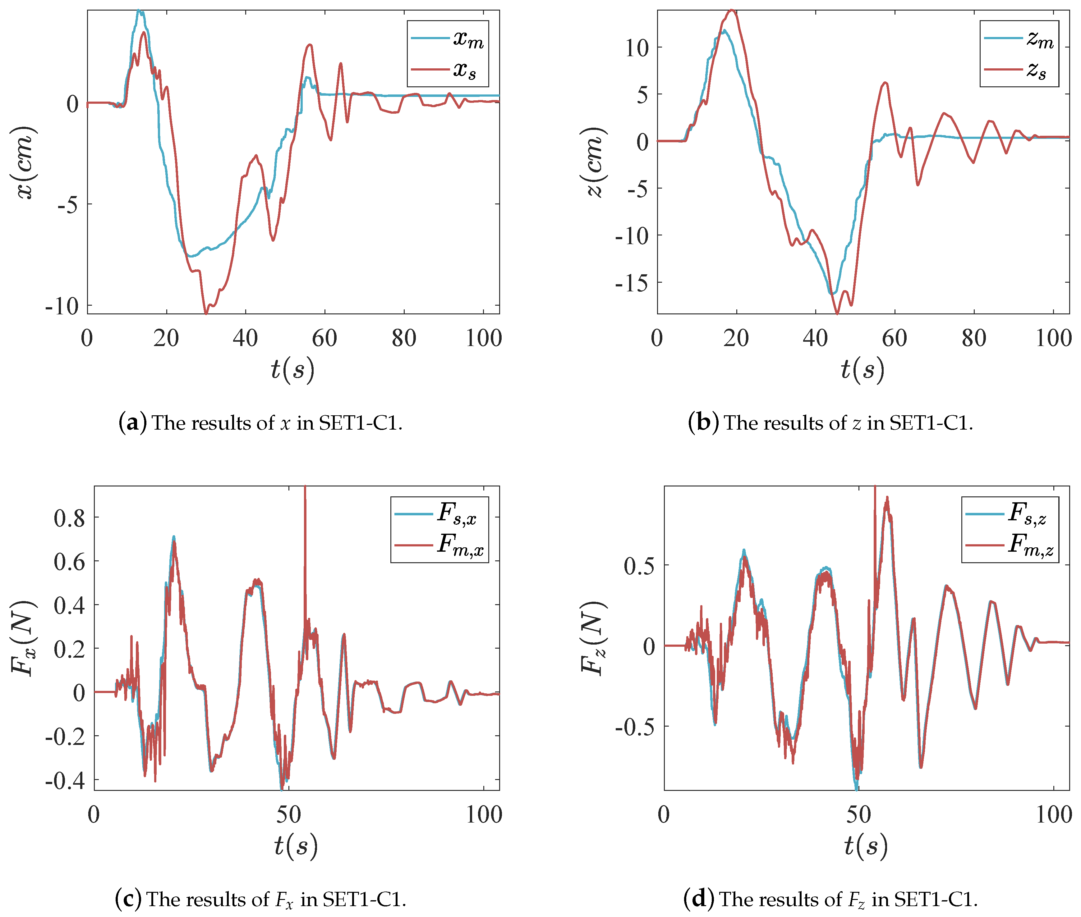
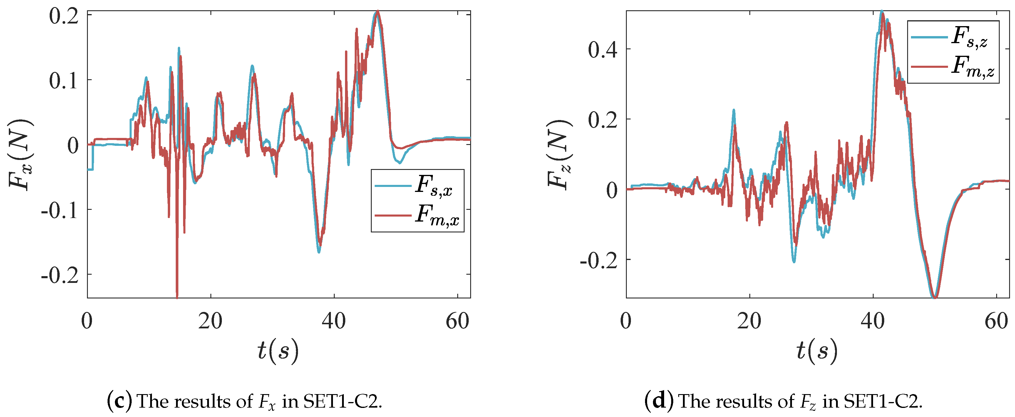
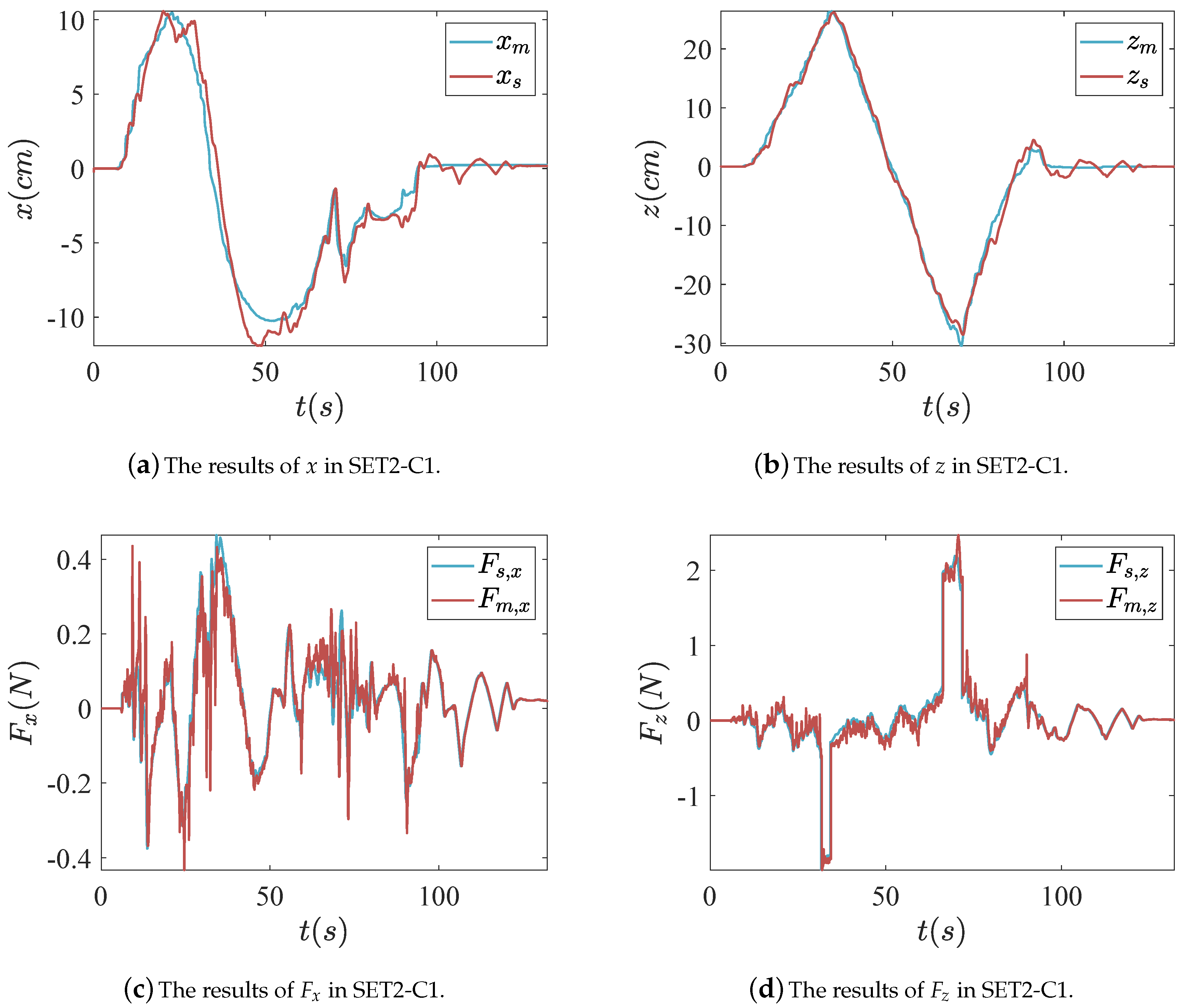
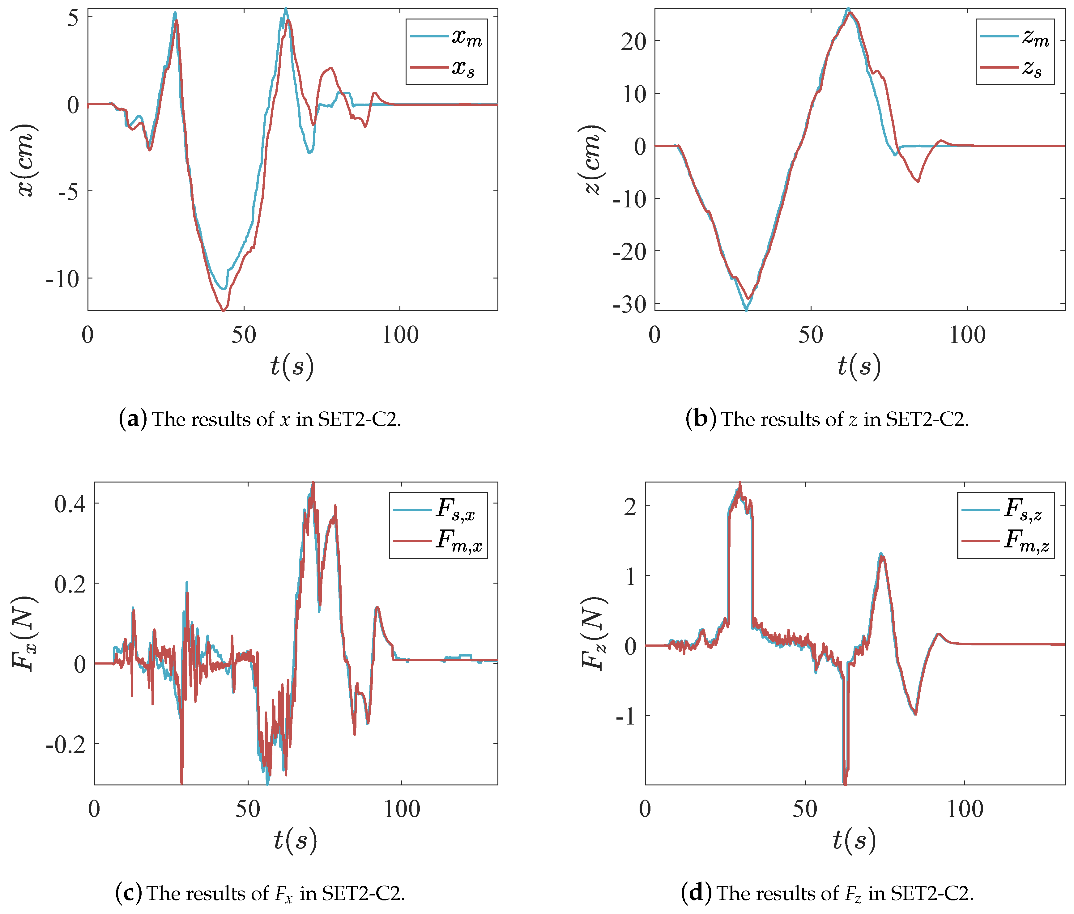
4.3. Experiment Results

The experiment results of free motion (Set1) are shown in Figure 10 and Figure 11, where the stylus is operated repletely with different control designs C1 and C2. To show the results of the practical teleoperation control experiments with virtual force feedback, the position signals and force signals of leader and follower robots are displayed by curves. x m denotes the position of the leader robot in X-axis, measured by the internal encoders of Touch device and z m denotes that in the Z-axis. Since there are no sensors in the motion subsystem of CHCM, its end-effector potions x m and z m are derived from actual cable lengths via established forward kinematics model, which are measured by the linear magnetic encoders of the driving structure of cables. Through the comparison of these position signals, the trajectory tracking performance of proposed teleoperation control scheme can be shown. F s , x represents the virtual force feedback in the X-axis produced by the virtual force feedback generation algorithm proposed in this paper, and that with subscript z denotes signals in the Z-axis. F m , x represents the force feedback signals transmitted to the leader robot through the modified wave transform structure. Through the comparison of the above signals, the system transparency can be verified.
It is shown that CHCM could track the desired motion trajectory and reach an ideal position when the force feedback is close to zero, which indicates the proposed method of forward and inverse kinematics solution is proper. Specifically, Figure 10a,b and Figure 11a,b show the response of CHCM among the X-axis or Z-axis during the free motion via control design C1 and C2, and that the position of follower could track the change of desired trajectory with a small error. Because of the similar expression of X ˙ s d and same value of b in C1 and C2, the position-tracking performance of C2 is approaching that of C1.
During free motion, the force feedback among the X-axis or Y-axis is generated only by the position-tracking error, which presents a state of flux shown in Figure 10c,d and Figure 11c,d. However, due to the influence of the velocity of leader X ˙ m caused by the wave variable architecture with regard to Equation (20), the transmitted force feedback to the leader is deteriorated in the control scheme C1, which may mislead the operator by providing imprecise perception of tracking errors, while the results of C2 show obviously better force feedback performance than that of C1 via introduction of K.
The experiment results of motion in free and constrained location (Set2) are shown in Figure 12 and Figure 13, where the end-effector of CHCM reaches and stays in constrained location, which is defined by a virtual boundary and described by a spring-damper.
The operator moves the stylus of leader robot toward an arbitrary direction in free space. It presents similar results to Set1 including position-tracking and force feedback performance, when the position of CHCM does not exceed the setting boundary (±18 cm in both X-axis or Z-axis). Then, the stylus is moved till the z coordinate value of follower robot reaches the boundary and remains for a short time, the generated virtual force feedback will show an observable sudden change shown in Figure 12c,d and Figure 13c,d.
When the stylus is released from constrained location, the follower robot comes back to free motion until reaching reverse boundary. In the process of the whole motion, the virtual force feedback in leader generated by Equation (22) provides the operator with information about position-tracking errors and how the follower robot gets touch with the boundary and constrained location. Thus, the collision between the follower and the setting boundary can be obviously perceived by the operator through the virtual force feedback generation algorithm. By comparing the force feedback curves in Figure 13 to those in Figure 12, it is shown that the negative effect of b on force feedback is reduced by the secondary parameter K, with more accurate force feedback in the leader.
As shown in Figure 10, Figure 11, Figure 12 and Figure 13, the control scheme C2 presents good trajectory tracking performance and more accurate force feedback compared to the control design C1 during motion in free or constrained locations, where the generation algorithm produces sensible force feedback.

5. Conclusions

In this paper, a cable-driven hyper-redundant continuum manipulator (CHCM) is introduced, then its forward and inverse kinematics model is established based on the geometry relationships of each joint module, which avoids time-consuming inversion and is applicable for real-time control in a teleoperation system. Inspired by a relatively new teleoperation control scheme, which could reduce wave reflections, a modified wave variable-based teleoperation control scheme is proposed with theoretically guaranteed stability and improved transparency via appropriate values of the impedance parameter b and the gain coefficient K, and a virtual force feedback generation algorithm is developed to provide operators with the perception of tracking errors and collision between the follower and the setting boundary.
The comparative experiments were carried out and the results show that the seamless combination of derived kinematics model of CHCM and teleoperation scheme with modified wave variable architecture achieves good trajectory tracking performance of CHCM and provides sensible and improved force feedback during free and constrained motion. This work provides a design of a remote control for a cable-driven manipulator and accurate perception of a follower’s motion state for operators.

Author Contributions

Conceptualization, Z.C. and W.S.; methodology, Z.C. and W.S.; software, L.Q.; validation, F.H., Z.C., W.S. and S.Z.; formal analysis, Z.C.; investigation, L.Q. and F.H.; resources, Z.C. and W.S.; data curation, L.Q.; writing—original draft preparation, L.Q.; writing—review and editing, F.H. and Z.C.; visualization, W.S. and S.Z.; supervision, Z.C. and W.S.; project administration, Z.C., W.S. and S.Z.; funding acquisition, Z.C. and W.S. All authors have read and agreed to the published version of the manuscript.

Funding

This work is funded by the National Natural Science Foundation of China (No.51705452 and No.52075476), and the Natural Science Foundation of Zhejiang Province, China (No. LY19E050016).

Conflicts of Interest

The authors declare no conflict of interest.

References

  1. Moran, M.E. Evolution of robotic arms. J. Robot. Surg. 2007, 1, 103–111. [Google Scholar] [CrossRef] [PubMed] [Green Version]
  2. Barbalata, C.; Dunnigan, M.W.; Petillot, Y. Coupled and decoupled force/motion controllers for an underwater vehicle-manipulator system. J. Mar. Sci. Eng. 2018, 6, 96. [Google Scholar] [CrossRef] [Green Version]
  3. Cianchetti, M.; Laschi, C.; Menciassi, A.; Dario, P. Biomedical applications of soft robotics. Nat. Rev. Mater. 2018, 3, 143–153. [Google Scholar] [CrossRef]
  4. McMahan, W.; Chitrakaran, V.; Csencsits, M.; Dawson, D.; Walker, I.D.; Jones, B.A.; Pritts, M.; Dienno, D.; Grissom, M.; Rahn, C.D. Field trials and testing of the OctArm continuum manipulator. In Proceedings of the 2006 IEEE International Conference on Robotics and Automation, Orlando, FL, USA, 15–19 May 2006. [Google Scholar]
  5. Anscombe, R.; Bryant, A.; Buckingham, R.; Ferguson, G.; Graham, A.; Lichon, M.; Green, B. Snake-Arm Robots: A New Approach to Aircraft Assembly; SAE Aerotech Congress: Warrendale, PA, USA, 2007. [Google Scholar]
  6. Tang, J.; Zhang, Y.; Huang, F.; Li, J.; Chen, Z.; Song, W.; Zhu, S.; Gu, J. Design and kinematic control of the cable-driven hyper-redundant manipulator for potential underwater applications. Appl. Sci. 2019, 9, 1142. [Google Scholar] [CrossRef] [Green Version]
  7. Webster, R.J.; Jones, B.A. Design and kinematic modeling of constant curvature continuum robots: A review. Int. J. Rob. Res. 2010, 29, 1661–1683. [Google Scholar] [CrossRef]
  8. Xu, W.; Liu, T.; Li, Y. Kinematics, dynamics, and control of a cable-driven hyper-redundant manipulator. IEEE/ASME Trans. Mechatron. 2018, 23, 1693–1704. [Google Scholar] [CrossRef]
  9. Zaraki, A.; Hayashi, Y.; Thorpe, H.; Strong, V.; Larsen, G.A.; Holderbaum, W. A leader-follower kinematic-based control system for a cable-driven hyper-redundant manipulator. In Proceedings of the International Conference on Advances in Robot Kinematics, London, UK, 18–19 November 2019. [Google Scholar]
  10. Liljebäck, P.; Pettersen, K.Y.; Stavdahl, ∅.; Gravdahl, J.T. A review on modelling implementation and control of snake robots. Robot. Auton. Syst. 2012, 1, 29–40. [Google Scholar] [CrossRef] [Green Version]
  11. Lipkin, K.; Brown, I.; Peck, A.; Choset, H.; Rembisz, J.; Gianfortoni, P.; Naaktgeboren, A. Differentiable and piecewise differentiable gaits for snake robots. In Proceedings of the 2007 IEEE/RSJ International Conference on Intelligent Robots and Systems, San Diego, CA, USA, 29 October–2 November 2007; pp. 1864–1869. [Google Scholar]
  12. Rollinson, D.; Choset, H. Pipe network locomotion with a snake robot. J. Field Robot. 2016, 33, 322–336. [Google Scholar] [CrossRef]
  13. Wright, C.; Buchan, A.; Brown, B.; Geist, J.; Schwerin, M.; Rollinson, D.; Tesch, M.; Choset, H. Design and architecture of the unified modular snake robot. In Proceedings of the IEEE International Conference on Robotics and Automation (ICRA), Saint Paul, MN, USA, 14–18 May 2012; pp. 4347–4354. [Google Scholar]
  14. Tesch, M.; Schneider, J.; Choset, H. Using response surfaces and expected improvement to optimize snake robot gait parameters. In Proceedings of the IEEE/RSJ International Conference on Intelligent Robots and Systems, San Francisco, CA, USA, 25–30 September 2011; pp. 1069–1074. [Google Scholar]
  15. Liljebäck, P.; Stavdahl, ∅.; Pettersen, K.Y.; Gravdahl, J.T. A modular and waterproof snake robot joint mechanism with a novel force/torque sensor. In Proceedings of the IEEE/RSJ International Conference on Intelligent Robots and Systems, Algarve, Portugal, 7–12 October 2012; pp. 4898–4905. [Google Scholar]
  16. Zhang, Z.; Yang, G.; Yeo, S.H. Inverse kinematics of modular cable-driven snake-like robots with flexible backbones. In Proceedings of the 2011 IEEE 5th International Conference on Robotics, Automation and Mechatronics (RAM), Qingdao, China, 17–19 September 2011; pp. 41–46. [Google Scholar]
  17. Hannan, M.W.; Walker, I.D. Kinematics and the implementation of an elephant’s trunk manipulator and other continuum style robots. J. Robot. Syst. 2003, 20, 45–63. [Google Scholar] [CrossRef]
  18. McMahan, W.; Jones, B.A.; Walker, I.D. Design and implementation of a multi-section continuum robot: Air-Octor. In Proceedings of the 2005 IEEE/RSJ International Conference on Intelligent Robots and Systems, Edmonton, AB, Canada, 2–6 August 2005; pp. 2578–2585. [Google Scholar]
  19. Wooten, M.; Frazelle, C.; Walker, I.D.; Kapadia, A.; Lee, J.H. Exploration and inspection with vine-inspired continuum robots. In Proceedings of the 2018 IEEE International Conference on Robotics and Automation (ICRA), Brisbane, Australia, 21–25 May 2018; pp. 1–5. [Google Scholar]
  20. Ananthanarayanan, H.; Ordóëez, R. Real-time inverse kinematics of (2n+1) DOF hyper-redundant manipulator arm via a combined numerical and analytical approach. Mech. Mach. Theory 2015, 91, 209–226. [Google Scholar] [CrossRef]
  21. Martín, A.; Barrientos, A.; Del, C.J. The Natural-CCD algorithm, a novel method to solve the inverse kinematics of hyper-redundant and soft robots. Soft Robot. 2018, 5, 242–257. [Google Scholar] [CrossRef] [PubMed]
  22. Espinoza, M.S.; Gonçalves, J.; Leitão, P.; Sánchez, J.L.G.; Herreros, A. Inverse kinematics of a 10 DOF modular hyper-redundant robot resorting to exhaustive and error-optimization methods: A comparative study. In Proceedings of the 2012 Brazilian Robotics Symposium and Latin American Robotics Symposium, Fortaleza, Brazil, 16–19 October 2012; pp. 125–130. [Google Scholar]
  23. Braganza, D.; Dawson, D.M.; Walker, I.D.; Nath, N. A neural network controller for continuum robots. IEEE Trans. Robot. 2007, 23, 1270–1277. [Google Scholar] [CrossRef]
  24. Chen, Z.; Pan, Y.J.; Gu, J. Integrated adaptive robust control for multilateral teleoperation systems under arbitrary time delays. Int. J. Robust Nonlinear Control 2016, 26, 2708–2728. [Google Scholar] [CrossRef]
  25. Chen, Z.; Huang, F.; Sun, W.; Gu, J.; Yao, B. RBF-Neural-Network-Based Adaptive Robust Control for Nonlinear Bilateral Teleoperation Manipulators With Uncertainty and Time Delay. IEEE/ASME Trans. Mechatron. 2020, 25, 906–918. [Google Scholar] [CrossRef]
  26. Chen, Z.; Huang, F.; Yang, C.; Yao, B. Adaptive Fuzzy Backstepping Control for Stable Nonlinear Bilateral Teleoperation Manipulators With Enhanced Transparency Performance. IEEE Trans. Ind. Electron. 2020, 67, 746–756. [Google Scholar] [CrossRef]
  27. Andrés, M.B.; Juan, R.G.; Iván, R.; Jaime, C.; Antonio, B. Design of a Hyper-Redundant Robot and Teleoperation Using Mixed Reality for Inspection Tasks. Sensors 2020, 20, 2181. [Google Scholar]
  28. Ren, L.; Omisore, O.M.; Han, S.; Wang, L. A master-slave control system with workspaces isomerism for teleoperation of a snake robot. In Proceedings of the 2017 39th Annual International Conference of the IEEE Engineering in Medicine and Biology Society (EMBC), Jeju Island, Korea, 11–15 July 2017; pp. 4343–4346. [Google Scholar]
  29. Rayne, P.B.; Leibrandt, K.; Gras, G.; Fraisse, P.; Crosnier, A.; Yang, G. Inverse kinematics control methods for redundant snakelike robot teleoperation during minimally invasive surgery. IEEE Robot. Autom. Lett. 2018, 3, 2501–2508. [Google Scholar] [CrossRef]
  30. Lawrence, D.A. Stability and transparency in bilateral teleoperation. IEEE Trans. Robot. Autom. 1992, 9, 625–637. [Google Scholar]
  31. Yang, X.; Hua, C.; Yan, J.; Guan, X. An exact stability condition for bilateral teleoperation with delayed communication channel. IEEE Trans. Syst. Man, Cybern. Syst. 2016, 46, 434–439. [Google Scholar] [CrossRef]
  32. Chen, Z.; Huang, F.; Chen, W.; Zhang, J.; Sun, W.; Chen, J.; Gu, J.; Zhu, S. RBFNN-based adaptive sliding mode control design for delayed nonlinear multilateral tele-robotic system with cooperative manipulation. IEEE Trans. Ind. Inform. 2020, 16, 1236–1247. [Google Scholar] [CrossRef]
  33. Tanner, N.A.; Niemeyer, G. Improving perception in time-delayed telerobotics. Int. J. Robot. Res. 2005, 24, 631–644. [Google Scholar] [CrossRef]
  34. Niemeyer, G.; Slotine, J.E. Stable adaptive teleoperation. IEEE J. Ocean. Eng. 1991, 16, 152–162. [Google Scholar] [CrossRef]
  35. Chen, Z.; Huang, F.; Sun, W.; Song, W. An improved wave-variable based four-channel control design in bilateral teleoperation system for time-delay compensation. IEEE Access 2018, 6, 12848–12857. [Google Scholar] [CrossRef]
  36. Bate, L.; Cook, C.D.; Li, Z. Reducing wave-based teleoperator reflections for unknown environments. IEEE Trans. Ind. Electron. 2011, 58, 392–397. [Google Scholar] [CrossRef]
  37. Ye, Y.; Liu, P.X. Improving trajectory tracking in wave-variable-based teleoperation. IEEE/ASME Trans. Mechatron. 2010, 15, 321–326. [Google Scholar]
  38. Ye, Y.; Liu, P.X. Improving haptic feedback fidelity in wave-variable-based teleoperation orientated to telemedical applications. IEEE Trans. Instrum. Meas. 2009, 58, 2847–2855. [Google Scholar]
  39. Hokayem, P.F.; Spong, M.W. Bilateral teleoperation: An historical survey. Automatica 2006, 42, 2035–2057. [Google Scholar] [CrossRef]
Figure 1. The general structure of CHCM, consisting of the driving subsystem and the motion subsystem.
Applsci 10 08031 g001
Figure 2. The details of driving or motion subsystems.
Applsci 10 08031 g002
Figure 3. The world coordinate system and joint angles definition.
Applsci 10 08031 g003
Figure 4. A geometric model of universal joint.
Applsci 10 08031 g004
Figure 5. Simplified kinematics model between joint angles and end-effector position.
Applsci 10 08031 g005
Figure 6. Modified wave variable architecture.
Applsci 10 08031 g006
Figure 7. Designed teleoperation control scheme for CHCM.
Applsci 10 08031 g007
Figure 8. The simulation result of the scattering matrix norm.
Applsci 10 08031 g008
Figure 9. The practical platform of proposed teleoperation system.
Applsci 10 08031 g009
Figure 10. The results of Set1-C1.
Applsci 10 08031 g010
Figure 11. The results of F z in SET1-C2.
Applsci 10 08031 g011aApplsci 10 08031 g011b
Figure 12. The results of Set2-C1.
Applsci 10 08031 g012
Figure 13. The results of Set2-C2.
Applsci 10 08031 g013
Table 1. The properties and values of some symbols.
SymbolPropertyValue
NNumber of all joints5
MNumber of through holes at endplates18
RRadius of tubular structure33.8 mm
DDistance from tubular structure to the center of universal joint12 mm
HLength of tubular structure106 mm
Table 2. Device models and software versions.
Device or SoftwareModel or Version
ActuatorsMaxon EC-max 30
Linear magnetic encoderLM10
Data acquisition deviceQuanser QPID-e
Real-time control softwareMATLAB 2018a, Quanser QUARC
Publisher’s Note: MDPI stays neutral with regard to jurisdictional claims in published maps and institutional affiliations.

