Article

Effects of Working Fluids on the Performance of a Roots Pump for Hydrogen Recirculation in a PEM Fuel Cell System

1
School of Energy and Power Engineering, Xi’an Jiaotong University, Xi’an 710049, China
2
Yantai Dongde Industry Co., Ltd., 331 Changjiang Road, Yantai 264006, China
*
Author to whom correspondence should be addressed.
Appl. Sci. 2020, 10(22), 8069; https://doi.org/10.3390/app10228069
Submission received: 11 September 2020 / Revised: 10 November 2020 / Accepted: 10 November 2020 / Published: 13 November 2020

Abstract

:
In this paper, the performance of a Roots pump for hydrogen recirculation in proton exchange membrane (PEM) fuel cell system is simulated based on CFD modeling. The Roots pump is in a three-lobe configuration with helical rotors, and it is developed specifically for fuel cell systems between 60 to 110 kW. A three-dimensional model of the Roots pump is established to predict the pump performance, including the flow rate and power consumption under various operating conditions. Extensive simulations were conducted and then verified experimentally by operating with working fluids of air and helium. Based on the validated CFD model, the contents of water vapor and nitrogen in the hydrogen recirculated are taken into account to evaluate the Roots pump performance numerically according to the actual conditions of the recirculating hydrogen at the stack outlet. It is shown that the volumetric efficiency and isentropic efficiency are improved with the increase fraction of water vapor and nitrogen. It is found that the performance of the Roots pump integrated in the PEM fuel cell system is between the performance of the pump working with air and helium. Finally, correlations of volumetric efficiency and isentropic efficiency are given based on the CFD results to show the general pattern of this kind of hydrogen pump. It is believed that these equations are very helpful to the design and operation control of the PEM fuel cell system.

Highlights

  • A three-dimensional (3D) CFD model of a hydrogen recirculation Roots pump with helical rotors is established to predict the performance.
  • The contents of water vapor and nitrogen in the hydrogen are taken into account in the model.
  • The characteristics of flow rate and power consumption are simulated based on the validated model by experiments.
  • Correlations of volumetric and isentropic efficiencies are given for the hydrogen pump in a PEM fuel cell system.

1. Introduction

The proton exchange membrane (PEM) fuel cell system has been used increasingly more often in the applications of various vehicles due to its advantages, such as high efficiency, compact structure and because it is easy to start [1]. In order to decrease hydrogen consumption and increase reliability, the configurations with hydrogen recirculation are widely adopted for the hydrogen supply to the stack of the fuel cell system in these applications [2]. A hydrogen pump is one of the most important components in the hydrogen supply loop and the behavior of the hydrogen pump has a significant impact on the performance the fuel cell system.
The accurate prediction of the hydrogen pump performance is an essential task in the design and operation of the PEM fuel cell system. On the one hand, a sub-model for describing the performance of the hydrogen pump is a critical part in the system-level simulation in the design of a PEM fuel system [3,4]. It is also very important for the realization of the control strategies during the operation of the fuel cell system [5,6]. On the other hand, the evaluation of the hydrogen pump performance is very challenging, both through experimental testing and theoretical modeling. The challenge comes mainly from the complex composition of the fluid recirculated by the pump. Despite that the hydrogen is excessively supplied to the stack of the fuel cell, there are usually some impurities being recirculated with the hydrogen, and these impurities include water vapor and nitrogen [7,8,9,10]. Regarding the experimental investigation, the performance measured with dry and pure hydrogen on a test rig differs greatly from the performance of the pump integrated in the PEM fuel cell system. It would be very expensive and time-consuming to evaluate the performance of the pump if all these impurities are presented and controlled in the experimental investigation. Therefore, the theoretical modeling and simulation of the performance of the hydrogen pump becomes a feasible and effective solution to meet this need from the fuel cell system [11,12].
The simulation of the hydrogen pump performance is of course dependent on the specific types of the pump. Up to now, the hydrogen pumps which have been widely used for hydrogen recirculation in the PEM fuel cell systems mainly include an ejector and mechanical pump. The ejector utilizes the pressure difference between the hydrogen tank and the fuel cell stack for providing energy. This kind of pump has advantages, such as having no moving parts, low maintenance cost and relatively high efficiency [13,14,15,16]. ‘Mechanical pump’ is actually the general name of a group of different pumps. According to the structures of the key components, the mechanical pump can be divided into several types such as the regenerative pump [17,18], claw pump [19], scroll pump [20,21] and Roots pump. The Roots pump belongs to the positive displacement machine and its advantages include high reliability, low cost and permission with reversible rotation. The hydrogen recirculation pump used in the fuel cell system of the Toyota Mirai is a Roots pump with two straight lobes [22].
Although the Roots pump has been used for hydrogen recirculation in the fuel cell system in the past, it is hard to find published papers related to the Roots pump for this application, except one primary simulation work by the current authors [23]. In our previous study, a three-dimensional unsteady flow simulation model of a three-lobes Roots pump in fuel cell system was established and solved based on the SST k-w turbulence model. The structured dynamic meshes of the deforming fluid domain was generated by Twinmesh software. The results revealed that the flow field is influenced by the pressure field and the mass flow fluctuation is affected greatly by the pressure ratio. The type of Roots pump studied previously has three straight lobes, instead of helical rotors in this study; moreover, the working gas is just pure hydrogen, and water vapor and nitrogen are not considered. In what way the working fluids affect the pump performance is the key consideration in this study. The vast majority of papers about Roots pump are related to applications such as air blowers and vacuum pumps. Nevertheless, all these studies provided invaluable insights and helpful information for theoretical modeling the performance of Roots pump for hydrogen recirculation. For example, it has been shown that the performance of the Roots pump can be calculated by thermo-fluid modeling based on one-dimensional chamber modeling with lumped parameters [24,25]. Moreover, it has also been indicated that the CFD simulation is more accurate and more detailed for predicting the performance of Roots machine, because it can simulate the velocity and pressure fields within the pump chamber and the leakage clearances [26,27,28,29,30]. Regretfully, as of the present study, simulations of a hydrogen pump [20,21] were based on pure hydrogen, and only together with water vapor considered for ejector [12,31,32]. These research results indicated that water vapor could apparently influence the entertainment performance of the ejector. Thus, there is still a big difference from real applications.
As mentioned above, the hydrogen recirculated by the Roots pump is associated with impurities including water vapor and nitrogen. The objective of this study is to find out the effects of these impurities on the performance of the Roots pump and to evaluate the performance of this kind of hydrogen pump under various operating conditions in the PEM fuel cell system. The investigation is performed by the simulation based on CFD modeling of the three-lobe Roots pump with helical rotors developed specifically for fuel cell systems between 60 to 110 kW. Furthermore, abundant verification experiments are conducted via running with air and helium. Based on this, the prediction of the flow rate and power consumption of this Roots hydrogen pump are carried out numerically under various operating conditions. The effects of water vapor and nitrogen that remained in the recirculated hydrogen on the pump performance are discussed in detail for the first time. In the end, correlations of volumetric efficiency and isentropic efficiency are given based on simulation results to show the general pattern of this kind of hydrogen pump. It is believed that these equations are very helpful to the design and operation control of the PEM fuel cell system.

2. Description of Anode Recirculation and Gas Composition

Figure 1 shows a simplified schematic diagram of the hydrogen recirculation loop in PEM fuel cell system. After throttling by a pressure regulator and an injector, the hydrogen from the hydrogen tank is mixed with the unreacted hydrogen recirculated by hydrogen pump and enters the fuel cell stack as anode fuel. The vast majority of the hydrogen entered into the stack is consumed to generate electric power, and the rest hydrogen is discharged from the stack together with water which is formed by the electrochemical process in the stack. Some contents of nitrogen diffusing from the cathode is usually in the fluid discharged from the anode of the stack, since the oxygen is supplied to the stack by means of compressed air. To limit the performance deterioration of the stack, the hydrogen purge valve is opened periodically if the content of the nitrogen exceeds a certain value. In the water separator before the pump, the liquid water is separated by cyclone or collision separation. Thus, the fluids that are recirculated by the hydrogen pump include hydrogen, nitrogen and water vapor. The effects of all these contents on the performance of the hydrogen pump should be investigated; this is the objective of this study.
In practice, the nitrogen concentration in the real system is difficult to determine because the temperature, relative humidity, current density and stoichiometric ratio could affect the concentration of nitrogen [33]. According to the research of Rabbani and Rokni [34], the nitrogen concentration in the PEMFC systems is below 3%. Wang et al. [35] performed a numerical study on the purging scheme of the anode cycle, and the nitrogen concentration at the outlet position changes between 0–60%. Karimaki et al. [36] measured experimentally the nitrogen fraction, which varies between 10–22% at the stack inlet for an 8-kW stack. It can be seen that the nitrogen concentration of different studies varies greatly, so the range of nitrogen concentration is considered as 5–25% in this study.

3. Simulation Model Development

3.1. Roots Pump Description

The Roots pump investigated in this study is in a three-lobe configuration with helical rotors, and it is developed specifically for a fuel cell system output power range from 60 to 110 kW. The pump is also required to operate steadily when the load of the fuel cell is down to 25%. The design parameters of the Roots pump are listed in Table 1 and the main parts are shown in Figure 2.
With the prototype of the Roots pump, extensive experimental testing was performed on test rigs with air, helium and hydrogen. The experimental results showed that the performance of the Roots pump is highly sensitive to the property of the working gas. Moreover, the Roots pump developed has been integrated successfully into three PEM fuel cell systems with an output of 60 kW, 80 kW and 110 kW. The operating parameters of the Roots pump in PEM fuel cell systems under various loads indicated that the efficiency of the Roots pump integrated in the fuel cell system is better than that measured with pure hydrogen on the test rig. This implies that the performance of the Roots pump is affected greatly by the impurities, such as water and nitrogen, which exist inevitably in the anode circuit of the PEM fuel cell system. Thus, this study is focused on the effects of the impurities on the performance of Roots pump through CFD simulation under various conditions.

3.2. Grid Generation

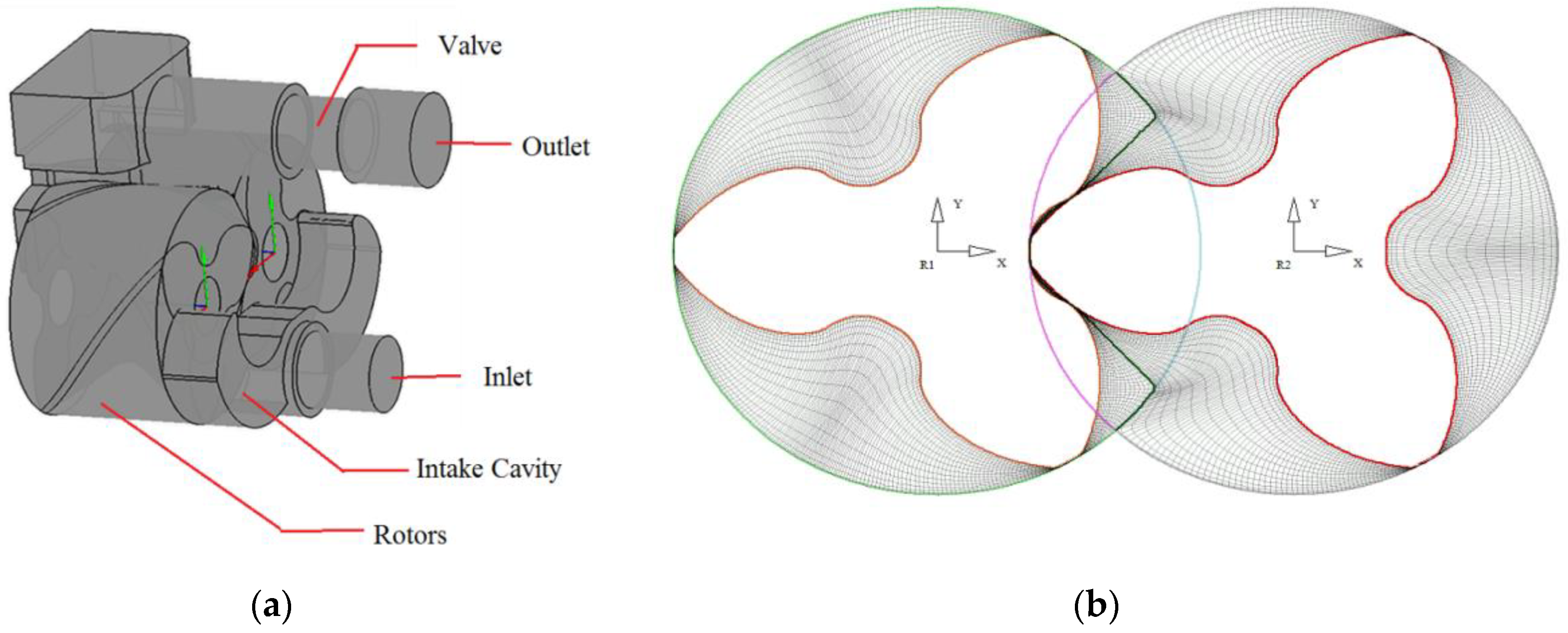
The Roots pump has two three-lobe rotors mounted on parallel shafts that rotate in opposite directions. The inlet and outlet domain are respectively connected with two end faces of the rotor, and the inlet and outlet pipes connect to the inlet and outlet domains respectively. Figure 3 shows the fluid domain and the rotor grids of the Roots pump. Stationary fluid domains are generated in ANSYS Meshing, which include the inlet domain, outlet domain and the solid regions in the casing. A valve is added in the outlet pipe to produce a discharge pressure in the actual system. The grids of the flow domain formed by the moving rotor are generated by the specific software named Twinmesh for dynamic grid generation. Stationary grids with 361,526 nodes and 0.2 mm first layer height are used in all cases, and four levels of rotor grids are generated to check the grid independence. It is acceptable because that mass flowrate result shows that the refinement of the grid result in a relatively slight change in flowrate no more than 0.5%. Rotor grids and stationary grids are combined with interfaces. The grids are generated and stored via Twinmesh for every one degree of the rotation angle, and the time step size is decided by both the rotation angle size and rotation speed.

3.3. Simulation Setup

The Ansys-CFX solver is used for the calculation by assuming the working fluid is an ideal gas. The working process is set as an adiabatic process, and the wall condition is assumed to be adiabatic. The SST turbulence model is adopted in the simulation and second order precision schemes are used. The pressure boundary condition is used for the inlet and outlet.
For a fluid of mixture, the gas constant can be defined by the mole fraction of each component:
R g = R Σ n i M i
where R is general gas constant which equals to 8.314 J/(mol·K).
In addition, its volumetric heat capacity c v and isobaric heat capacity c p are determined by the mass fraction of each component:
c p = Σ x i c p i
c v = Σ x i c v i
Assuming that the mixture is an ideal gas, its isentropic index κ can be defined as follows:
κ = c p c v = Σ x i κ i
The mole fraction of hydrogen n H 2 can be obtained according to Dalton’s law of partial pressure. According to the working principle of a fuel cell stack, a lot of water during operation will be produced, which needs to be separated before entering the Roots pump as shown in Figure 1. Thus, the mixture entering the Roots pump is saturated with water vapor.
n H 2 = p s p s a t , w a t e r ( T s ) p s n N 2
where p s is the suction pressure, T s is the suction temperature and p s a t , w a t e r is the saturation pressure of water vapor at a specific temperature.

3.4. Performance Parameters Definition

As a positive displacement machine, the performance of a Roots pump is mainly indicated by the volume flow rate and power consumption. In addition, volumetric efficiency and isentropic efficiency are introduced in order to compare the pumps with different sizes and various operating conditions.
The volume flow rate is defined as the volume of the gas delivered by the pump per unit time with the state of the gas being converted to the parameters at the inlet of the pump. It is the capability of the Roots pump to deliver the fluids in the anode recirculate loop of the fuel cell system. Moreover, the volume flow rate is also an indicator of the initial cost of the pump because the geometrical size of a Roots pump is dependent on its volume flow rate as well as rotation speed. In actuality, for a positive displacement pump or compressor, there is always an optimum speed for the best performance and minimum size. High speed can reduce the size and thus reduce the cost, but the performance will become worse for higher flow losses. That is to say, a pump or compressor with a certain volume flowrate implies the relation between size and speed. With the actual average mass flow rate calculated by the CFD simulation, the volume flow rate of the Roots pump can be obtained by the state equation of the ideal gas:
V = 60 m R g T s / p s
where Rg is the gas constant calculated by Equation (1).
The volumetric efficiency is defined as the ratio of the volume flow rate to the theoretical capacity of the Roots pump, and a higher volumetric efficiency implies better sealing within the Roots pump:
η V = V V t
The theoretical capacity Vt of the Roots pump is the geometric function of the rotor profile and is defined as the swept volume per revolution multiplied by the rotation speed of the pump:
V t = V r n = 2 Z A 0 L n
where V r is the displaced volume per rotation, Z is the lobe number, L is the rotor length, n is the rotation speed and A0 is the area between two lobes of the rotor and the casing.
The power consumption of the Roots pump is the electric power input to the controller of the pump. Most of the power is used to compress and deliver the fluid from the inlet to the outlet of the Roots pump, while a small part of it is used to compensate the losses in the controller and in the motor as well as the friction power consumed within the Roots pump by the timing-gears, bearing, and shaft seals. In the following sections of the present study, these losses are neglected in order to focus on the compression process of the Roots pump. Then, the power consumption of the pump can be calculated with the average torque M, which are obtained based on the CFD simulation results:
N = 2πMn/60
The isentropic efficiency is defined as the ratio of the isentropic compression power consumption to the power consumption of the Roots pump. A higher isentropic efficiency means a more efficient compression process and less power consumption of the pump. It can be calculated by the following equation:
η i s = N i s / N
where the isentropic compression power consumption N i s can be expressed as:
N i s = κ κ 1 p s V ( ( p d p s ) κ 1 κ 1 )
where κ is the isentropic index calculated by Equation (2).

4. Results and Discussion

4.1. Validation of the CFD Model

As mentioned in Section 3.1, the Roots pump studied has been tested extensively under various operating conditions. The experimental tests were built to calibrate and validate the results simulated by the CFD model established. The experimental test with working fluids of the helium and air were used instead of hydrogen for the sake of safety. The schematic diagram of the experimental test rig is shown in Figure 4. It should be noted that the supplied air was suctioned by the Roots pump from the environment when the working fluid is air. As seen in Figure 4, the fresh helium was supplied by a helium tank at the start-up stage of the experimental test. Then, the helium supply could be cut off by a tee valve, and the helium recirculation was performed to recycle the supplied helium. The low- and high-pressure regulators were used to adjust the inlet and outlet pressure of the Roots pump, respectively. The flow rate of helium recirculation was measured by a Coriolis mass flow meter with a maximum range of 1000 L/min and an uncertainty of 0.8%. The pressure and temperature of Roots pump inlet and outlet were measured by the pressure and temperature sensors, respectively.
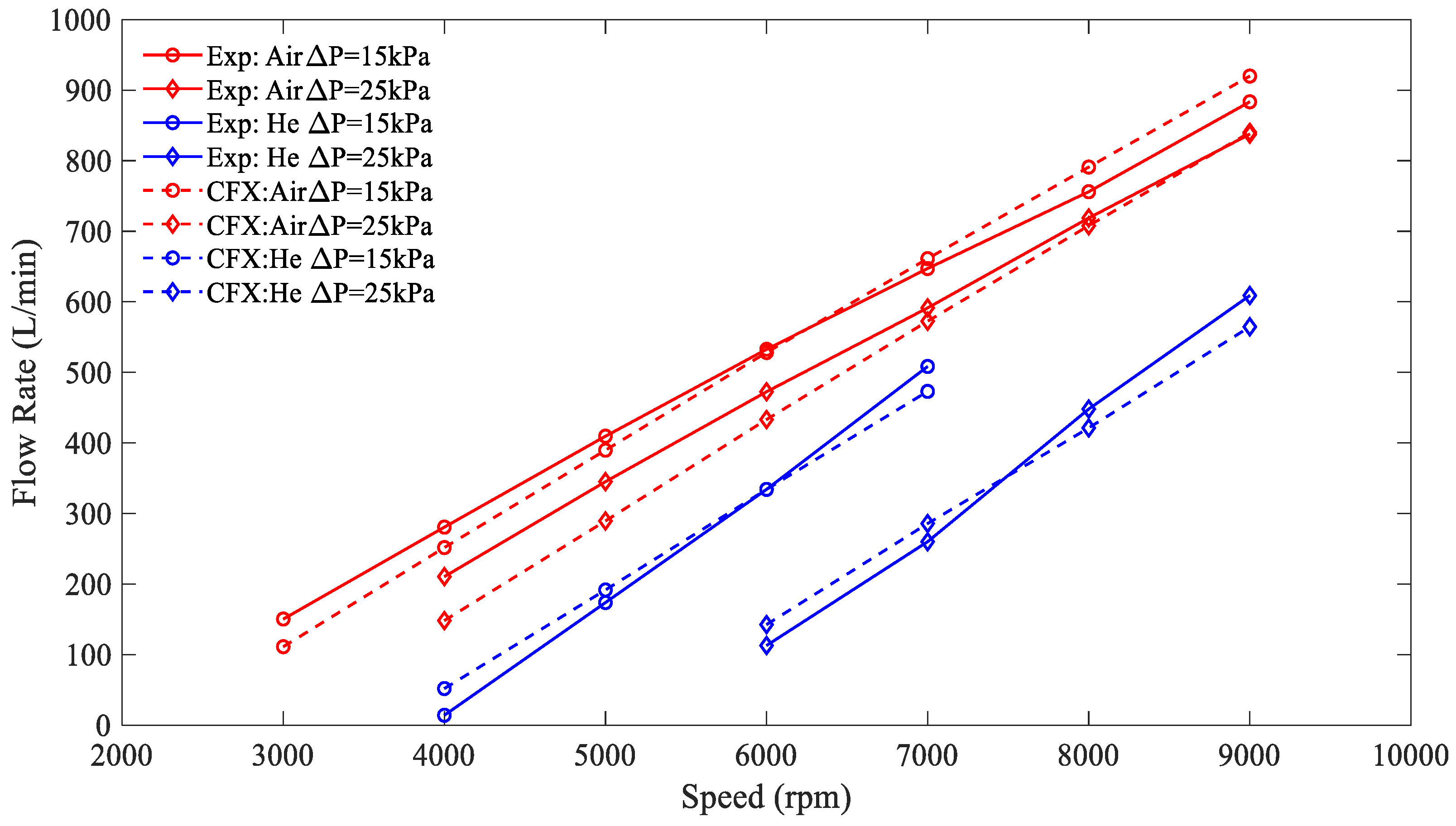
The suction temperature of the air and helium is 30 °C and the suction pressure of the helium is 200 kPa, while that of the air is the ambient pressure. As shown in Figure 5, the flow rate simulated for helium with a speed of 6000 rpm and pressure difference of 15 kPa is calibrated by changing the clearances within the Roots pump to have the error as small as possible between the data measured and that simulated. Then, all the volume flow rates under other operating conditions are simulated and validated based on these clearances adjusted as above. Except for the clearance at the discharge end, which is 0.15 mm, the values of other clearances are all of 0.1 mm for the clearance between the rotors, the clearance between the rotor tip and the casing as well as the clearance between the rotor end face and the casing at the suction end. The values of 0.1 mm and 0.15 mm are the normally applied clearances in most commercially available roots pumps.
Figure 5 indicates the flow rate comparison of Roots pump between the experimental values and the simulation results under various rotation speed and pressures difference with working as air and helium. As can be seen, the flow rate increases with the rising of the rotation speed and reduction of pressure difference, and this variation trend of the experiments and simulation is consistent. Moreover, the simulated flow rate under various conditions agreed very well with the measured data by the maximum deviations, which was less than ±10% within the main operating speed range between 5000 rpm and 9000 rpm, except for the very low speed condition, used rarely. Thus, it is believable that the CFD modeling can be used to predict and evaluate the performance of the Roots pump under various operating conditions and with gases having different properties.

4.2. Effect of Water Vapor

In order to study the performance of the Roots pump working with saturated wet hydrogen, the effect of water vapor on volumetric efficiency and isentropic efficiency under different suction temperature are conducted numerically. As indicated in Figure 6a, the volumetric efficiency increases almost linearly with an increase of the suction temperature, which is also an indication of the water vapor content. Furthermore, it shows that volumetric efficiency is improved greatly at a lower rotation speed and larger pressure difference with an increase of suction temperature. These results can be explained by the different properties of the mixture under various temperatures. In the CFD simulation, the dynamic viscosity and molar mass are considered for the working fluids. The dynamic viscosity of water vapor is close to that of hydrogen, but its molar mass is much higher. With the increase of suction temperature, the water vapor accounts for more of the mixture, since the saturation pressure goes up. At the same time, the molar mass of the mixture increases rapidly, while the dynamic viscosity increases slightly. Therefore, it could be deduced that the molar mass has a dominant effect on the leakage, and the water vapor helps to improve the volumetric efficiency.
A similar pattern to volumetric efficiency can also be found in isentropic efficiency between suction temperatures in Figure 6b. The difference is that the change of the isentropic efficiency with the temperature is slightly smaller than that of the volumetric efficiency. For example, when the pressure difference is 15 KPa and the rotation speed is 9000 rpm, the volumetric efficiency of the Roots pump is improved by 9% from 50% to 59%, while the isentropic efficiency is improved by 6% from 47% to 53% with the increasing of suction temperature from 60 °C to 80 °C. Similarly, this could also be caused by reduced leakage, which means reduced internal energy loss.

4.3. Effect of Nitrogen

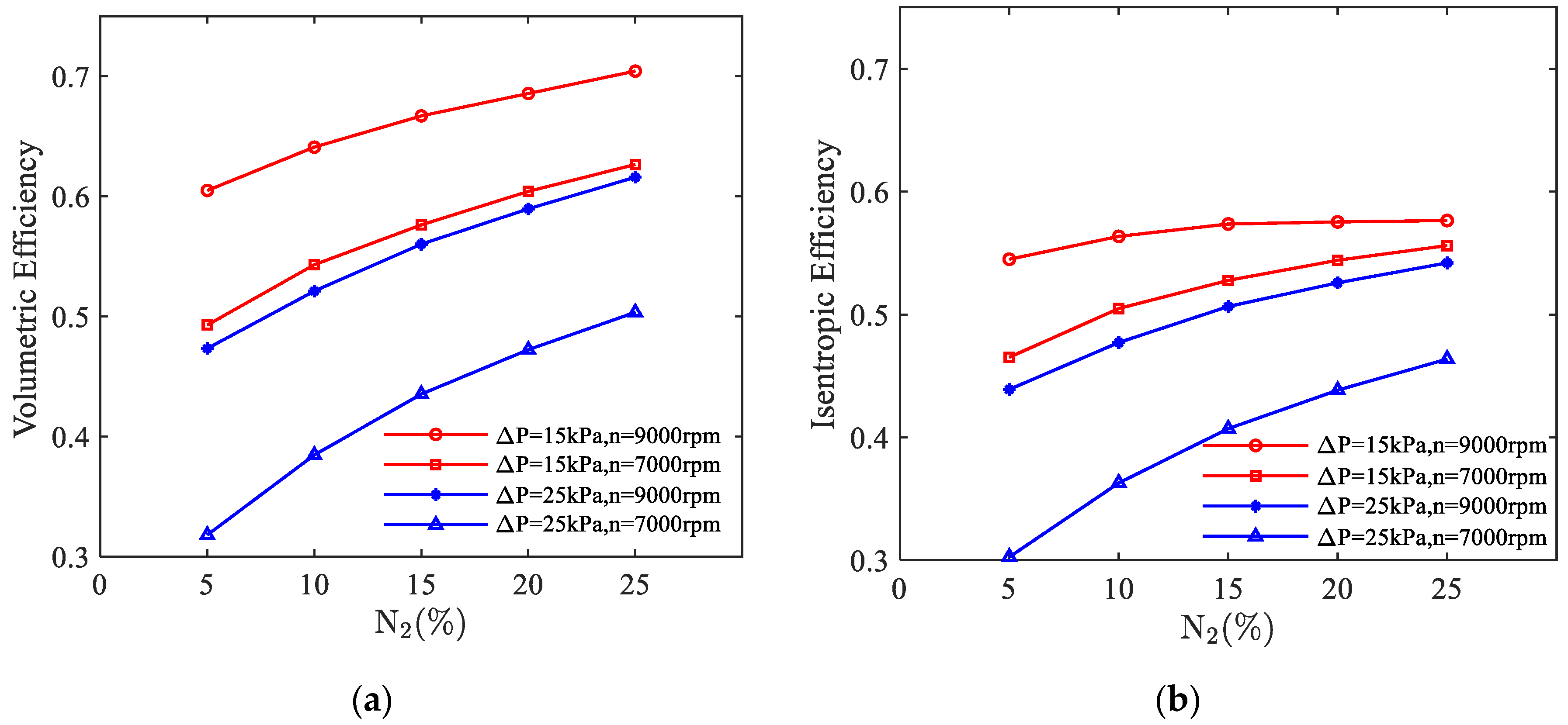
In actual operation of the fuel cell stack, there is more or less nitrogen mixed in the recirculating hydrogen, as mentioned in the previous section. Figure 7a reveals the effect of the nitrogen fraction on the volumetric efficiency under a different rotation speed and pressure difference. With the increase of nitrogen fraction, the volumetric efficiency increased rapidly at first and then increased slowly. From the four different conditions, a reduction of increment is displayed at a lower pressure difference or higher rotation speed, for the same reason as explained for water vapor. In fact, nitrogen plays the same role as water vapor in terms of leakage, with even higher mole mass and larger dynamic viscosity. Although as the proportion of nitrogen increases from 5% to 25% and the proportion of hydrogen decreases from 80% to 60%, the absolute volume flow of hydrogen still increases slightly at a pressure difference of 25 kPa. This result can be attributed to the improvement in volumetric efficiency. Figure 7b represents the effect of nitrogen on the isentropic efficiency, showing similar trends as volumetric efficiency but with smaller increments.
As can be seen from the Figure 7a,b, taking the condition of pressure difference of 15 KPa and speed of 9000 rpm for example, the volumetric efficiency increased by 10% from 60.5% to 70.4% with an increase of nitrogen fraction from 5% to 25%; however, the isentropic efficiency just increased by 3% from 54.5% to 57.6% with the same change in nitrogen fraction. The reason is likely because the volumetric efficiency is mainly affected by the leakage rate, but the isentropic efficiency is influenced both by the leakage and flow resistance. With the increasing of the nitrogen content, the molecular weight and density of the mixture increase, which will reduce the leakage rate and also increase the flow losses. Thus, the increase rate of the isentropic efficiency is smaller than that of the volumetric efficiency, which means that the volumetric efficiency is more sensitive to the change of nitrogen. When the speed is high and the pressure difference is low, the effect of flow resistance is more significant than that of the leakage due to the larger flowrate, while the isentropic efficiency is even less sensitive than the volumetric efficiency, as shown in Figure 7.

4.4. Comparison of Performance with Various Working Gases

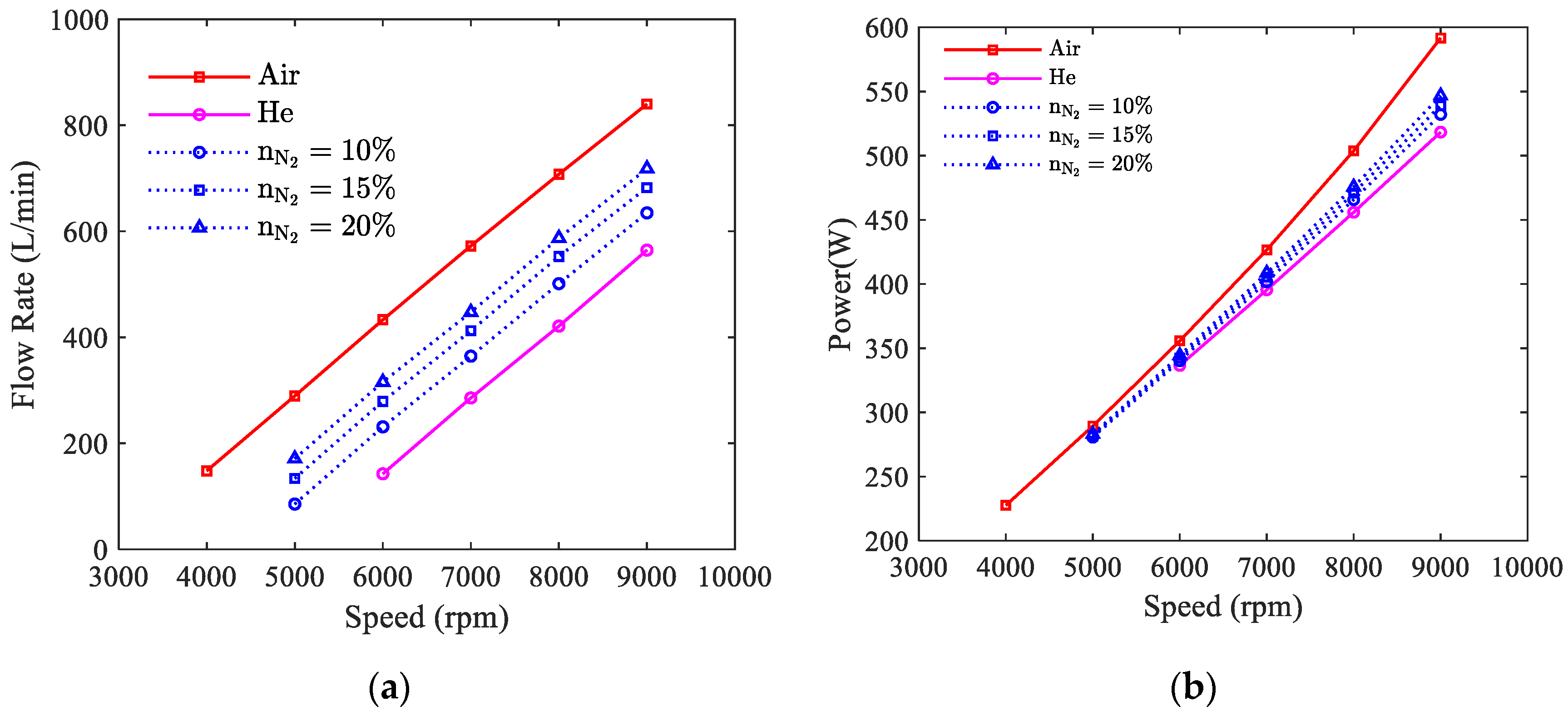
The simulation results of the volume flow rate and the power consumption of the Roots pump with various working gases are presented and compared in Figure 8. The suction temperature for both the air and helium is 30 °C and that for all cases with hydrogen is 70 °C. The pressure differences for all the cases are 25 kPa, and the suction pressures are all 200 kPa, except for the suction pressure for air, which is equal to the ambient pressure. For a given speed, it can be seen from Figure 8 that the volume flow rate of the Roots pump increases with the increase of the contents of nitrogen. Generally speaking, the performance of the Roots pump operating under the typical working conditions of the PEM fuel cell system is between the performance of the pump working with air and helium. As can be seen from the Figure 8a, the absolute volume flowrate with the mixture containing a nitrogen fraction of 15% is 158 L/min less than with air, but is 118 L/min more than with helium. This discrepancy is almost the same under the different speed conditions. This is because the absolute leakage is almost the same under different speeds. This implies that the performance of the Roots pump can be evaluated on the test rig with air or helium, and the testing results can be used to represent the performance of the hydrogen pump integrated in the PEM fuel cell system.

4.5. Correlations for the Volumetric and Isentropic Efficiency

The capacity and power consumption of the Roots hydrogen pump are influenced by the operation parameters and working fluids properties. In order to realize the fast and accurate matching between the hydrogen recycling content of stack and the capacity of the pump, a performance equation is needed for engineering application. Based on a great amount of the simulated data mentioned above, equations can be correlated for the volumetric efficiency and isentropic efficiency in function of the pressure difference, suction temperature, ration speed and nitrogen content. The basic form would be:
η = f ( Δ P , n , T s , n N 2 )
As shown in Figure 8, the flow rate of the pump presents an obvious linear relationship with the speed. This means that the absolute leakage is almost the same under different speed. Thus, the relative leakage is low and volumetric efficiency is high when the speed is high. Hence, the impact of rotation speed on volumetric efficiency can be considered as:
η v = 1 a / ( V r n )
Considering the pressure difference and composition separately, the correlation equation could be given as:
η v = 1 f ( T s , n N 2 ) / ( V r n ) g ( Δ P )
Applying the least square method, a specific correlation is obtained as:
η v = 1 ( 12 T s + 2667 ) n N 2 2 + ( 19.6 T s 2780 ) n N 2 5.1 T s + 1063 V r n Δ P 2.1 25 2.1
The most important value of this correlation equation is to supply a simple adjusting method to meet the quick response of the pump capacity with the stack requirement. By combining Equations (5) and (13), the rotation speed needed corresponding to the required flow rate of pump can be expressed as below:
n = V T a r g e t / V r [ ( 12 T s + 2667 ) n N 2 2 + ( 19.6 T s 2780 ) n N 2 5.1 T s + 1063 ] Δ P 2.1 25 2.1 / V r
Based on the derived volumetric efficiency, the correlation formula of isentropic efficiency can be obtained:
η i s = 0.4 V r n η V [ ( 1.6546 0.05 Δ P ) n N 2 + 0.1559 T s + 50.182 ] n / 1000 0.8363 T s ( 916 28 Δ P ) n N 2 25.94
Furthermore, the power consumption of the pump for compressing the gas in real conditions can be expressed as below. This can be used to show how much parasitic power is consumed by the hydrogen pump:
N = N i s / η i s
As shown in Figure 9, these two correlation equations can achieve high accuracy within the range of pressure difference of 15–25 kPa, a temperature of 70–80 °C, a rotation speed of 5000–9000 rpm and a nitrogen mole fraction of 5–25%. In most cases, the absolute error of the predicted value of volumetric efficiency did not exceed 1%, which could precisely reflect the influence of the four factors on volumetric efficiency. Although most of coefficients in the correlation equation are fitted at a speed of 7000 and a pressure difference of 25 kPa, we can see from Figure 9 that high accuracy can still be ensured at different speeds and pressure differences, which suggests that the assumption about correlation equation is feasible. Through these two correlations, the volumetric efficiency and isentropic efficiency of the Roots blower can be quickly estimated as the four factors change.

5. Conclusions

The performance of a Roots pump for hydrogen recirculation in PEM fuel cell system is simulated based on three-dimensional CFD modeling. The effects of the working fluids on the performance of the Roots pump are presented. Here is the summary of the major findings.
(1) The CFD model can be used to predict the performance of the Roots pump based on the validation with the experimental data measured with working gas of air and helium, respectively. The maximum deviation of the simulation results from the experiments is 9.4% for air and 9.8% for helium within the main operating speed range between 5000 rpm and 9000 rpm.
(2) The volumetric efficiency and isentropic efficiency of the Roots pump are improved separately by 9% and 6% with the increasing of suction temperature from 60 °C to 80 °C under the condition of pressure difference of 15 KPa and speed of 9000 rpm. With the increasing of nitrogen fraction from 5% to 25%, the volumetric efficiency and isentropic efficiency are improved by 10% and 3% under the same condition. This effect would clearly benefit the recirculation of hydrogen in the anode loop of the stack.
(3) The performance of the Roots pump integrated in the PEM fuel cell system is between the performance of the pump working with air and helium. The absolute volume flowrate with mixture containing nitrogen fraction of 15% is less 158 L/min than that of with air, but is more 118 L/min than that of with helium for the Roots pump studied. This implies that the performance of the Roots pump can be evaluated on the test rig with air or helium.
(4) The correlations of the volumetric efficiency and isentropic efficiency based on the CFD results are presented to reflect the general pattern of this kind of hydrogen pump. It is believed that these equations are very helpful to the design and operation control of the PEM fuel cell system.
Further experimental test should consider the performance measurements of the Roots pump with working gas of the mixture same as the discharge from the stack outlet to correct the correlation and also the low temperature start test is worth to be carried out to research the effects of water vapor and liquid on the reliability of the Roots pump.

Author Contributions

Conceptualization, J.F., L.X., B.W. and H.W.; validation, L.X., B.W. and H.W.; investigation, J.F. and L.X.; resources, Z.X.; writing—original draft preparation, J.F. and L.X.; writing—review and editing, J.F. All authors contributed to the final manuscript. All authors have read and agreed to the published version of the manuscript.

Funding

This work is supported by the National Key Research and Development Program of China (Grant No.2018YFB0105303) and the Technology Innovation and Application Development Program of Chongqing [Grant No. cstc2019jscx-zdztzxX0035].

Conflicts of Interest

The authors declare no conflict of interest.

Nomenclature

A0Area between two lobes of the rotor and the casing: mm2
LRotor length, mm
mMass flow rate, kg/min
MTorque, N m
nRotation speed of the rotor, rpm
n i mole fraction of component i
NPower consumption, W
PPressure, kPa
ΔPPressure difference, kPa
VVolume flow rate, L/min
V r Displaced volume per rotation (L/r)
R g Gas constant
x i Mass fraction of component i
ZLobe numbers of the rotor
Greek symbols
η i s Isentropic efficiency
η v Volumetric efficiency
κ Isentropic index
Subscripts
dDischarge
sSuction
thTheoretical
Abbreviation
CFDComputational Fluid Dynamic
PEMFCProton Exchange Membrane Fuel Cell
SSTShear-Stress Transport

References

  1. Chen, X.; Li, W.; Gong, G.; Wan, Z.; Tu, Z. Parametric analysis and optimization of PEMFC system for maximum power and efficiency using MOEA/D. Appl. Therm. Eng. 2017, 121, 400–409. [Google Scholar] [CrossRef]
  2. Shen, K.-Y.; Park, S.; Kim, Y.-B. Hydrogen utilization enhancement of proton exchange membrane fuel cell with anode recirculation system through a purge strategy. Int. J. Hydrogen Energy 2020, 45, 16773–16786. [Google Scholar] [CrossRef]
  3. Shao, Y.; Xu, L.; Zhao, X.; Li, J.; Hu, Z.; Fang, C.; Hu, J.; Guo, D.; Ouyang, M. Comparison of self-humidification effect on polymer electrolyte membrane fuel cell with anodic and cathodic exhaust gas recirculation. Int. J. Hydrogen Energy 2020, 45, 3108–3122. [Google Scholar] [CrossRef]
  4. Kim, M.S.; Kim, D.K. Parametric study on dynamic heat and mass transfer response in polymer electrolyte membrane fuel cell for automotive applications. Appl. Therm. Eng. 2020, 167, 114729. [Google Scholar] [CrossRef]
  5. He, J.; Choe, S.-Y.; Hong, C.-O. Analysis and control of a hybrid fuel delivery system for a polymer electrolyte membrane fuel cell. J. Power Sources 2008, 185, 973–984. [Google Scholar] [CrossRef]
  6. He, H.; Quan, S.; Wang, Y.-X. Hydrogen circulation system model predictive control for polymer electrolyte membrane fuel cell-based electric vehicle application. Int. J. Hydrogen Energy 2020, 45, 20382–20390. [Google Scholar] [CrossRef]
  7. Guo, Q.; Ye, F.; Guo, H.; Ma, C.F. Gas/Water and Heat Management of PEM-Based Fuel Cell and Electrolyzer Systems for Space Applications. Microgravity Sci. Technol. 2016, 29, 49–63. [Google Scholar] [CrossRef]
  8. Zhang, S.; Chen, B.; Shu, P.; Luo, M.; Xie, C.; Quan, S.; Tu, Z.; Yu, Y. Evaluation of performance enhancement by condensing the anode moisture in a proton exchange membrane fuel cell stack. Appl. Therm. Eng. 2017, 120, 115–120. [Google Scholar] [CrossRef]
  9. Pan, T.; Shen, J.; Sun, L.; Lee, K.Y. Thermodynamic modelling and intelligent control of fuel cell anode purge. Appl. Therm. Eng. 2019, 154, 196–207. [Google Scholar] [CrossRef]
  10. Li, F.; Du, J.; Zhang, L.; Li, J.; Li, G.; Zhu, G.; Ouyang, M.; Chai, J.; Li, H. Experimental determination of the water vapor effect on subsonic ejector for proton exchange membrane fuel cell (PEMFC). Int. J. Hydrogen Energy 2017, 42, 29966–29970. [Google Scholar] [CrossRef]
  11. Brunner, D.A.; Marcks, S.; Bajpai, M.; Prasad, A.K.; Advani, S.G. Design and characterization of an electronically controlled variable flow rate ejector for fuel cell applications. Int. J. Hydrogen Energy 2012, 37, 4457–4466. [Google Scholar] [CrossRef]
  12. Nikiforow, K.; Koski, P.; Karimäki, H.; Ihonen, J.; Alopaeus, V. Designing a hydrogen gas ejector for 5 kW stationary PEMFC system—CFD-modeling and experimental validation. Int. J. Hydrogen Energy 2016, 41, 14952–14970. [Google Scholar] [CrossRef]
  13. Maghsoodi, A.; Afshari, E.; Ahmadikia, H. Optimization of geometric parameters for design a high-performance ejector in the proton exchange membrane fuel cell system using artificial neural network and genetic algorithm. Appl. Therm. Eng. 2014, 71, 410–418. [Google Scholar] [CrossRef]
  14. Besagni, G.; Mereu, R.; Inzoli, F.; Chiesa, P. Application of an integrated lumped parameter-CFD approach to evaluate the ejector-driven anode recirculation in a PEM fuel cell system. Appl. Therm. Eng. 2017, 121, 628–651. [Google Scholar] [CrossRef]
  15. Kuo, J.-K.; Jiang, W.-Z.; Li, C.-H.; Hsu, T.-H. Numerical investigation into hydrogen supply stability and I-V performance of PEM fuel cell system with passive Venturi ejector. Appl. Therm. Eng. 2020, 169. [Google Scholar] [CrossRef]
  16. Xue, H.; Wang, L.; Zhang, H.; Jia, L.; Ren, J. Design and investigation of multi-nozzle ejector for PEMFC hydrogen recirculation. Int. J. Hydrogen Energy 2020, 45, 14500–14516. [Google Scholar] [CrossRef]
  17. Badami, M.; Mura, M. Theoretical model with experimental validation of a regenerative blower for hydrogen recirculation in a PEM fuel cell system. Energy Convers. Manag. 2010, 51, 553–560. [Google Scholar] [CrossRef]
  18. Badami, M.; Mura, M. Leakage effects on the performance characteristics of a regenerative blower for the hydrogen recirculation of a PEM fuel cell. Energy Convers. Manag. 2012, 55, 20–25. [Google Scholar] [CrossRef]
  19. Wang, J.; Jiang, X.; Cai, Y. Investigation of a novel circular arc claw rotor profile for claw vacuum pumps and its performance analysis. Vacuum 2015, 111, 102–109. [Google Scholar] [CrossRef]
  20. Zhang, Q.; Feng, J.; Wen, J.; Peng, X. 3D transient CFD modelling of a scroll-type hydrogen pump used in FCVs. Int. J. Hydrogen Energy 2018, 43, 19231–19241. [Google Scholar] [CrossRef]
  21. Zhang, Q.; Feng, J.; Zhang, Q.; Peng, X. Performance prediction and evaluation of the scroll-type hydrogen pump for FCVs based on CFD–Taguchi method. Int. J. Hydrogen Energy 2019, 44, 15333–15343. [Google Scholar] [CrossRef]
  22. Konno, N.; Mizuno, S.; Nakaji, H.; Ishikawa, Y. Development of Compact and High-Performance Fuel Cell Stack. SAE Int. J. Altern. Powertrains 2015, 4, 123–129. [Google Scholar] [CrossRef]
  23. Xing, L.F.; He, Y.N.; Wen, J.; Peng, X.Y. Three-dimensional CFD Modelling of a Roots Blower for Hydrogen Recirculation in Fuel Cell System. In Proceedings of the 2018 International Compressor Engineering Conference, Purdue University, West Lafayette, Indiana, 9–12 July 2018; Paper 2562. Available online: https://docs.lib.purdue.edu/icec/2562 (accessed on 21 December 2018).
  24. Mimmi, G.; Pennacchi, P. Compression Load Dynamics in a Special Helical Blower: A Modeling Improvement. J. Mech. Des. 1999, 123, 402–407. [Google Scholar] [CrossRef]
  25. Burmistrov, A.; Belyaev, L.; Ossipov, P.; Fomina, M.; Khannanov, R. Combined experimental and calculation study of conductance of Roots pump channels. Vacuum 2001, 62, 331–335. [Google Scholar] [CrossRef]
  26. Huang, Z.F.; Liu, Z.X. Numerical study of a positive displacement blower. Proc. Inst. Mech. Eng. Part C J. Mech. Eng. Sci. 2009, 223, 2309–2316. [Google Scholar] [CrossRef]
  27. Hsieh, C.-F. A new curve for application to the rotor profile of rotary lobe pumps. Mech. Mach. Theory 2015, 87, 70–81. [Google Scholar] [CrossRef]
  28. Hsieh, C.-F.; Deng, Y.-C. A design method for improving the flow characteristics of a multistage Roots pumps. Vacuum 2015, 121, 217–222. [Google Scholar] [CrossRef]
  29. Sun, S.-K.; Zhao, B.; Jia, X.-H.; Peng, X.-Y. Three-dimensional numerical simulation and experimental validation of flows in working chambers and inlet/outlet pockets of Roots pump. Vacuum 2017, 137, 195–204. [Google Scholar] [CrossRef]
  30. Singh, G.; Sun, S.; Kovacevic, A.; Li, Q.; Bruecker, C. Transient flow analysis in a Roots blower: Experimental and numerical investigations. Mech. Syst. Signal. Process. 2019, 134, 106305. [Google Scholar] [CrossRef]
  31. Wang, X.; Xu, S.; Xing, C. Numerical and experimental investigation on an ejector designed for an 80 kW polymer electrolyte membrane fuel cell stack. J. Power Sources 2019, 415, 25–32. [Google Scholar] [CrossRef]
  32. Yin, Y.; Fan, M.; Jiao, K.; Du, Q.; Qin, Y. Numerical investigation of an ejector for anode recirculation in proton exchange membrane fuel cell system. Energy Convers. Manag. 2016, 126, 1106–1117. [Google Scholar] [CrossRef]
  33. Baik, K.D.; Kim, M.S. Characterization of nitrogen gas crossover through the membrane in proton-exchange membrane fuel cells. Int. J. Hydrogen Energy 2011, 36, 732–739. [Google Scholar] [CrossRef]
  34. Rabbani, A.; Rokni, M. Effect of nitrogen crossover on purging strategy in PEM fuel cell systems. Appl. Energy 2013, 111, 1061–1070. [Google Scholar] [CrossRef] [Green Version]
  35. Wang, B.; Deng, H.; Jiao, K. Purge strategy optimization of proton exchange membrane fuel cell with anode recirculation. Appl. Energy 2018, 225, 1–13. [Google Scholar] [CrossRef]
  36. Karimäki, H.; Perez, L.; Nikiforow, K.; Keränen, T.; Viitakangas, J.; Ihonen, J. The use of on-line hydrogen sensor for studying inert gas effects and nitrogen crossover in PEMFC system. Int. J. Hydrogen Energy 2011, 36, 10179–10187. [Google Scholar] [CrossRef]
Figure 1. Schematic diagram of the hydrogen supply loop in a proton exchange membrane (PEM) fuel cell system.
Applsci 10 08069 g001
Figure 2. Roots pump: (a) components of pump body; (b) assembly of pump body and motor.
Applsci 10 08069 g002
Figure 3. Simulation model of the Roots pump: (a) fluid domain; (b) rotor grids.
Applsci 10 08069 g003
Figure 4. The schematic diagram of the experimental test rig.
Applsci 10 08069 g004
Figure 5. Simulation model validation.
Applsci 10 08069 g005
Figure 6. Effect of water vapor on the performance: (a) volumetric efficiency; (b) isentropic efficiency.
Applsci 10 08069 g006
Figure 7. Effect of nitrogen on the performance: (a) volumetric efficiency; (b) isentropic efficiency.
Applsci 10 08069 g007
Figure 8. Comparison of the performance with various working gases: (a) flow rate; (b) power consumption.
Applsci 10 08069 g008
Figure 9. Comparison between the simulated and fitted value: (a) volumetric efficiency; (b) isentropic efficiency.
Applsci 10 08069 g009
Table 1. Design parameters of the Roots pump.
ParametersValue
Volume flow rate (L/min)500
Suction temperature (°C)60~80
Suction pressure (kPa)180~220
Pressure difference (kPa)>20
Relative humidity100%
Lobes of rotor3
Center distance between the rotors (mm)43.4
Outside diameter of rotor (mm)64.2
Length of rotor (mm)40
Wrap angle of rotor (°)95
Displaced volume per rotation (L/r)0.135
Rated rotation speed of rotor (rpm)8000
Tip peripheral speed of rotor (m/s)26.9
Theoretical volume flow rate (L/min)1082
Publisher’s Note: MDPI stays neutral with regard to jurisdictional claims in published maps and institutional affiliations.