Article

The Effect of a Composite Nanostructure on the Mechanical Properties of a Novel Al-Cu-Mn Alloy through Multipass Cold Rolling and Aging

1
College of Materials and Metallurgy, Guizhou University, Guiyang 550025, China
2
Guizhou Electric Power Research Institute, Guiyang 550007, China
3
Guizhou Institute of Technology, College of Materials and Energy Engineering, Guiyang 550003, China
4
High Performance Metal Structure Material and Manufacture Technology National Local Joint Engineering Laboratory, Guiyang 550025, China
*
Authors to whom correspondence should be addressed.
Appl. Sci. 2020, 10(22), 8109; https://doi.org/10.3390/app10228109
Submission received: 21 October 2020 / Revised: 12 November 2020 / Accepted: 13 November 2020 / Published: 16 November 2020
(This article belongs to the Section Nanotechnology and Applied Nanosciences)

Abstract

:
An effective approach composed of solution treatment, multipass cold rolling and aging was developed to improve the strength and ductility of novel Al-Cu-Mn alloys. This approach increased the yield strength by 214 MPa over that of the conventional peak-aged samples while maintaining a good elongation of 8.7%. The microstructure evolution was examined by confocal laser scanning microscopy (CLSM), transmission electron microscopy (TEM) and X-ray diffraction (XRD). During postaging, deformed structures underwent a considerable decrease in dislocation density and typical dislocation network structures were formed. At the same time, highly dispersed nanoprecipitates and extensive ultrafine grains and nanograins were generated. These nanoprecipitations enabled effective dislocation pinning and accumulation during tension deformation. Therefore, composite nanostructures containing ultrafine grains, nanograins, dislocation network structures and nanoprecipitates were responsible for the simultaneous increases in strength and ductility. This paper provides a new understanding of designing composite nanostructure materials for achieving high strength and good ductility that is expected to be used for other age-hardenable alloys and steels.

1. Introduction

Traditional methods to increase the strength of Al alloys mainly include solid solution strengthening and precipitation hardening. In recent years, ultrafine-grained (UFG) and nanograined (NG) materials have proven to be effective means to strengthen aluminum alloys. Severe plastic deformation (SPD) techniques such as equal channel angular pressing (ECAP), accumulative roll bonding (ARB) and high pressure torsion (HPT) can refine aluminum alloys to UFG/NG materials [1,2,3,4,5], which can significantly improve the strength of the alloy. However, due to the low dislocation storage capacity of UFG/NG materials, the tensile ductility is often insufficient [2,3]. In addition, the above methods have their own disadvantages; for example, it is difficult to handle large samples using ECAP and HPT and the plates are easy to separate during ARB. Therefore, to improve the processing performance and commercial applications of UFG/NG aluminum alloys, it is essential to improve their work-hardening ability while ensuring their high strength, which can help delay local deformation (necking) under tensile deformation and thus improve uniform elongation.
At present, many methods have been used to improve the work-hardening ability of UFG/NG aluminum alloys: (i) the introduction of a bimodal structure of coarse grains and nanosized grains, in which the nanosized grains mainly enhance the strength and the coarse grains provide ductility [6,7]; (ii) the preparation of a large number of nanotwins to accommodate additional dislocations [8,9,10] and (iii) the introduction of nanoparticles/precipitates to effectively prevent dislocation movement [11,12]. Different methods have been used to build bimodal structures to improve the uniform elongation of UFG/NG materials [6,7] but these methods are inefficient and technically difficult. In addition, tensile ductility sometimes increases at the expense of strength [10]. In contrast, the introduction of nanoparticles/precipitates into UFG/NG aluminum alloys is a potential method to achieve both high strength and good tensile ductility. For example, cryorolling combined with low-temperature aging can simultaneously improve the strength and tensile ductility of nanograined 7075 aluminum alloys [12]. Introducing a large number of nanoprecipitates into the matrix by low-temperature reaging is conducive to the accumulation of dislocations during the tensile process, which can significantly improve the uniform elongation of nanograined alloys. However, this rolling method needs to be carried out in a cryogenic liquid nitrogen environment and a certain time of cryogenic treatment is needed between each pass, which involves high risk and high energy consumption. Therefore, it is of great significance to improve the mechanical properties of UFG/NG materials based on existing processing methods.
The above discussion shows that UFG/NG alloys with nanoparticles/precipitates not only exhibit enhanced strength but also possess good ductility. The main purpose of this paper is to achieve high strength and good ductility in a UFG/NG Al-Cu-Mn alloy through the design of a composite nanostructure (mainly involving UFG and NG, dislocations of specific density and high density of nanoparticle/precipitates). The composite nanostructures were prepared by a thermomechanical treatment process. The process included solution treatment, multipass cold rolling and aging. The microstructure evolution of the alloy during the process was quantitatively analyzed by confocal laser scanning microscopy (CLSM), transmission electron microscopy (TEM), X-ray diffraction (XRD) and scanning electron microscopy (SEM). The formation of composite nanostructures in this alloy is discussed. In addition, the relationship between the microstructure parameters and mechanical properties of the alloy is also discussed in detail.

2. Materials and Methods

2.1. Materials

The new Al-Cu-Mn alloy was independently developed by China, possesses good corrosion resistance and thermal intensity and has been used as a reflection panel for 500 m diameter radio telescopes. The Al-Cu-Mn alloy uses industrial pure Al as the raw material and Cu as the main strengthening element and microalloying elements such as Mn, Ti and Zr are also added. The main components (wt.%) of the material measured by an AS6 JAGUAR desktop wavelength dispersive X-ray fluorescence spectrometer are Cu (6.21%), Mn (0.37%), Si (0.12%), Cr (0.079%), Fe (0.07%), Zr (0.057%), Ti (0.051%) and balance Al.

2.2. Methods

Samples (40 mm × 20 mm × 5 mm) were taken from the raw materials and quenched immediately to room temperature after solution treatment at 803 K for 840 min. Such samples are referred to as the solution treated (ST) samples hereafter. A few of the ST samples were then aged at 433 K for up to 1500 min and reached the peak aging (PA) state at 600 min. The other ST samples were cold rolled (CR) with good lubrication conditions at room temperature from 5 mm to 0.5 mm by multiple passes to an accumulated true strain of ε = 2.3 with <5% for each rolling pass. The rolled sheet was water cooled after a few passes to avoid deformation heating. The rolled samples were then aged at 373 K, 403 K and 433 K for up to 1500 min. CR-373K (420 min) represented the CR sample aged at 373 K for 420 min and CR-373K (1200 min) represented the CR sample aged at 373 K for 1200 min. An FM800 microhardness tester was used to measure the Vickers microhardness of the samples on the rolling direction (RD)-transverse direction (TD) plane to track the evolution of aging hardening. A load of 200 gram force (gf) with a dwell time of 10 s was used. Ten points were tested for each sample and the average value was obtained. Room temperature tensile tests were carried out on an MTS810 universal testing machine along the RD with a tensile rate of 1 mm/min. The room temperature tensile samples were processed into a dog-bone shape with a gage length of 15 mm and a width of 5 mm. At least three specimens for each condition were tested to ensure the accuracy of the experimental results. Subsequently, the fracture behavior of the alloy in different states was observed by SEM. The samples for optical microscopy were prepared by standard metallographic techniques and the results were analyzed on a LEXT OLS5000 laser confocal microscope. To reveal the microstructural evolution of the alloy under different conditions, an FEI G2 F20 TEM instrument operating at 200 kV was used. The (111), (200) and (220) incomplete pole figures (χ = 0–80° and Φ = 0–360°) were obtained by a Bruker D8 Discover X-ray diffractometer. The orientation distribution functions (ODFs) were then calculated by the series expansion method based on these three-incomplete-pole data [13]. The volume fractions of the texture components were then calculated by the decomposition method [14]. To estimate the dislocation densities of the as-deformed samples and subsequent aging samples, the microcrystallite sizes and the lattice microstrain of the samples were measured by the Williamson–Hall method [15]. Through the equation Bcos θ = K λ d + ε sin θ (where λ is the wavelength of Cu Kα radiation (0.154 nm), K is a constant of approximately 0.9 and θ is the Bragg angle), Bcosθ and the sinθ were fitted linearly. The microstrains and microcrystallite size were calculated from the slopes and intercepts of the fitted curve and then used to calculate the dislocation densities of the CR and CR-373K samples according to the equation of ρ = 2 3 ε / db [16] (where ρ is the dislocation density and b is Burgers vector, which has a magnitude of 0.286 nm for aluminum alloys [17]).

3. Results

3.1. Mechanical Properties

Figure 1a shows hardness curves of CR samples aged at 373 K, 403 K and 433 K. Before aging, the hardness of the CR samples was 174 V. It can be seen that during the aging process at 433 K, the hardness decreased continuously with the aging time. After aging for 1500 min, the hardness of the alloy decreased from 174 HV to approximately 102 HV, a decrease of approximately 41.38%. During the aging at 403 K, the hardness of the alloy decreased smoothly. After aging for 1500 min, the alloy hardness decreased from approximately 174 HV to approximately 122 HV, a decrease of approximately 29.89%. When aging at 373 K, the hardness value peaked twice. At the beginning of the aging process, the hardness of the alloy decreased and the first hardness peak, at 420 min, had a value of 171 HV. The hardness then decreased and gradually increased after fluctuating. The hardness of the samples reached a second peak (181 HV) after 1200 min of aging and then decreased. Tensile results are shown in Figure 1b. After PA treatment, the ultimate tensile strength (UTS), yield strength (YS) and elongation to failure (Ef) were 475 MPa, 350 MPa and 11.8%, respectively. Figure 1b shows that the UTS, YS and Ef of the CR samples were 571 MPa, 528 MPa and 4.2%, respectively. For the CR-373K (420 min) samples, the UTS and YS decreased to 544 MPa and 484 MPa, respectively, whereas the Ef increased to 5.4%. It is worth noting that the UTS, YS and El significantly increased to 614 MPa, 564 MPa and 8.7% for the CR-373K (1200 min) samples compared with the CR samples.
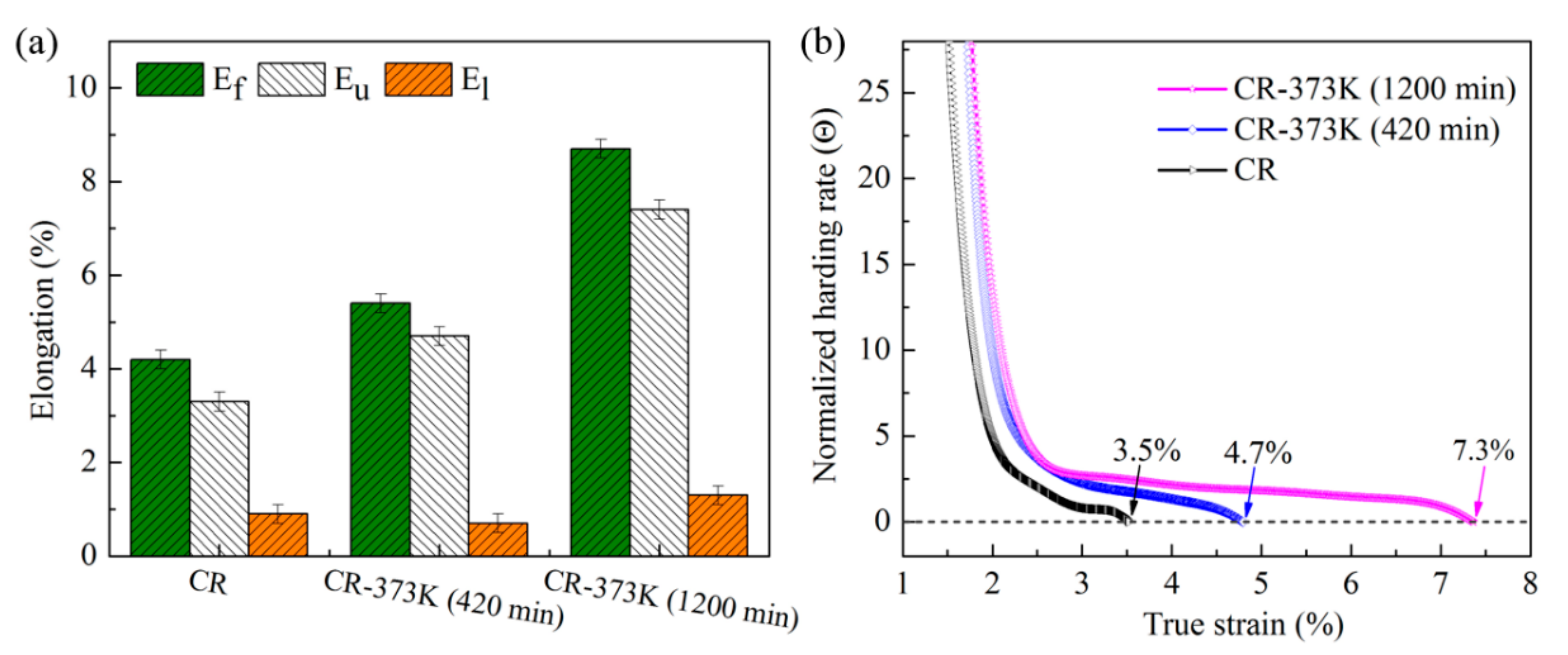
Based on the engineering stress-strain curve in Figure 1b, measuring the plastic strain increments before and after the peak stress resulted in the uniform elongation (Eu) and local elongation (El) of the tensile specimen in Figure 2a. Figure 2a shows that the Ef value of the tensile specimen was mainly contributed by Eu. In contrast, the El values contribute little. In general, the Eu value was employed to characterize the uniform deformation capability of a material, which could be determined using the Considère criterion σ = σ ε ε ˙ [12] (where σ is the true stress and ε is the true strain). As shown in Figure 2a, the CR samples had the lowest Eu value (3.3%). With prolonged aging, the Eu value increased gradually and the Eu value of the CR-373K (1200 min) samples was 7.4%. Moreover, the uniform deformation capability or Eu value of materials was directly related to the work-hardening rate, which was determined by the formula Θ = 1 σ σ ε ε ˙ [12]. When Θ > 0, dislocations could be further stored during deformation and then work-hardening occurred. When Θ < 0, deformation mainly occurred in a local area, which caused the alloy to enter the necking stage. Continued deformation broke the alloy. In the work-hardening rate curves of Figure 2b, the CR-373K sample had a higher Θ than the CR sample. In the CR-373K (1200 min) samples, the Θ value was still >0 when the true strain was >7% but the Θ values of the CR samples at true strain >3.5% were <0.

3.2. Microstructures

3.2.1. Optical Microstructures

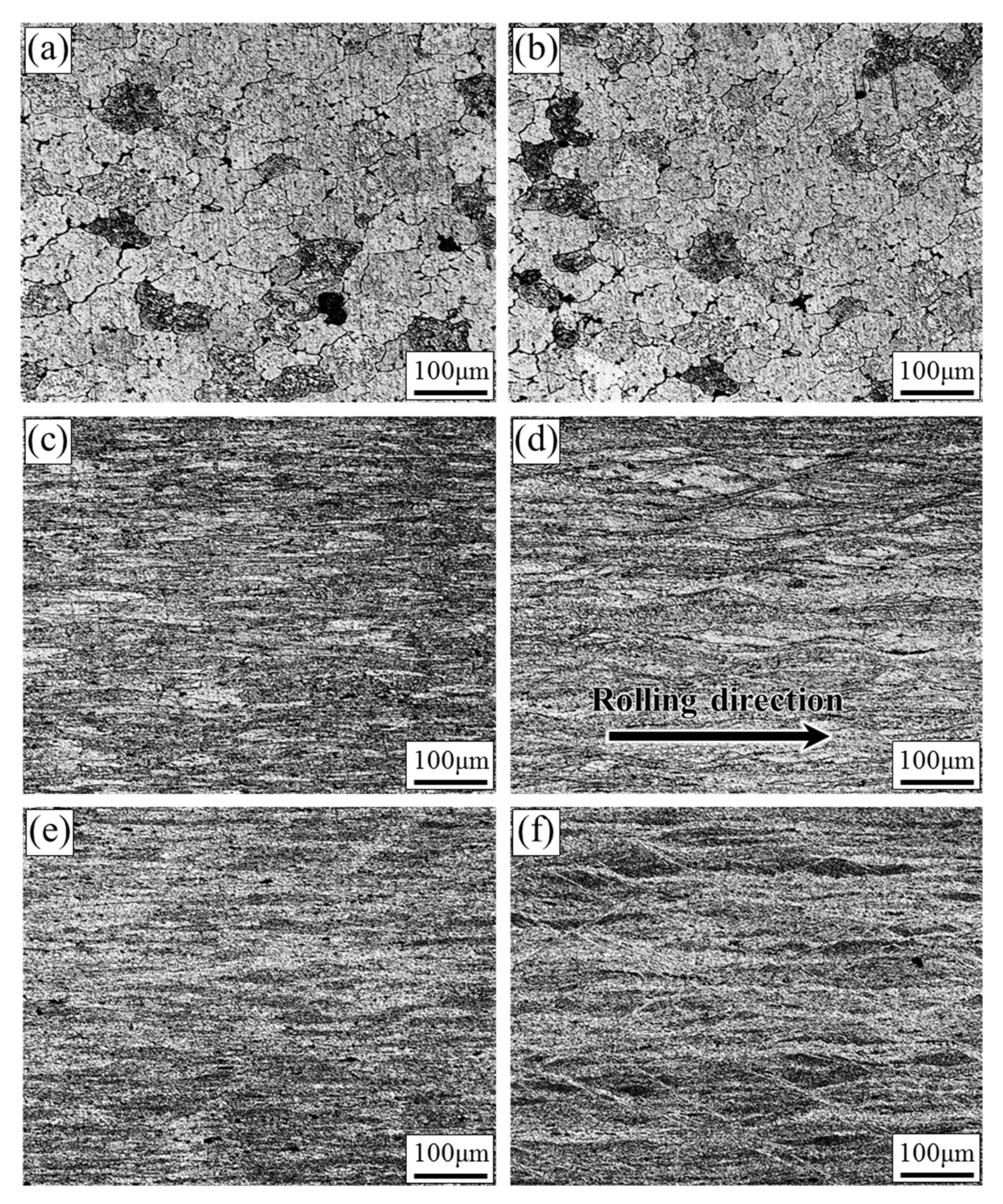
Figure 3a,c,e and Figure 3b,d,f show the longitudinal and transverse sections of the PA, CR and CR-373K (1200 min) samples, respectively. Figure 3a,b show that the microstructure of the PA samples contained equiaxed grains with an average size of 150 μm. Figure 3c,d shows the morphology of the CR samples and the principal microstructural characteristic was the presence of a typical fibrous structure. Compared with the PA sample boundaries, the grain boundaries had a low contrast and the microstructure displayed a low contrast overall because many dislocations were introduced into the matrix. As no recrystallization occurred, the microstructure after aging was almost the same as those of the CR samples.

3.2.2. TEM Microstructures

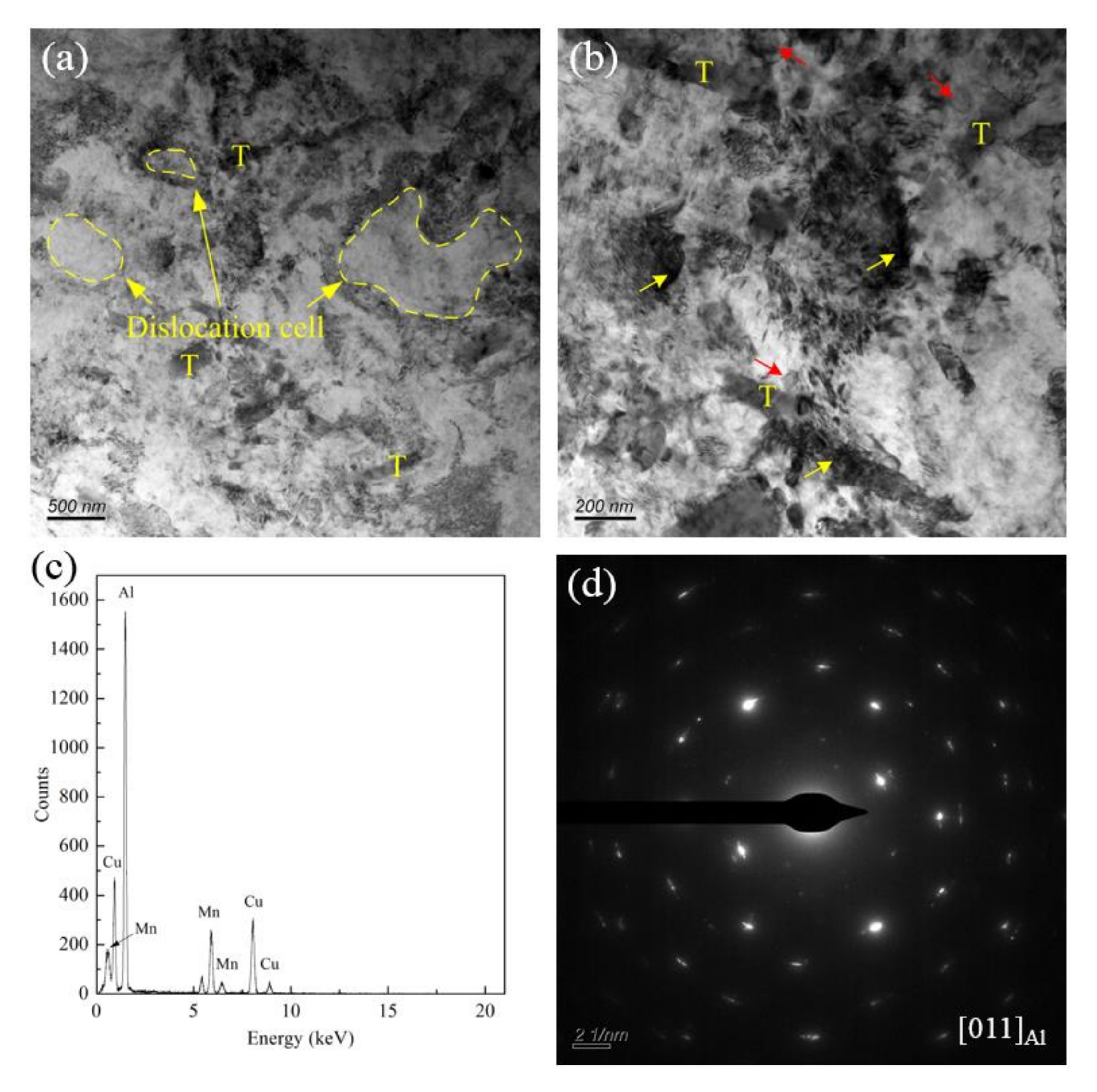
The microstructure of the CR samples was examined in more detail using TEM. Figure 4 shows a typical bright-field TEM micrograph of an as-deformed sample. Large rod-like dispersoids with an average size of 200 nm were found in Figure 4b and identified as the T phase with a composition of Al4(CuMn) by energy-dispersive X-ray spectroscopy (EDS) analysis (Figure 4c), which was consistent with the results in the literature [18,19,20]. These T phase particles were retained from the ST sample and played a critical role in dislocation accumulation and microstructure refinement during cold rolling [21]. After CR, a high density of dislocations was trapped around the T phase (yellow arrows in Figure 4b) while in areas without the T phase, the dislocation density was much lower and typical dislocation cell structures were formed (Figure 4a). It is worth noting that micro/nanoscale grains (~150–200 nm) appeared in local regions (red arrows in Figure 4b). In addition, apart from the T phase, no other precipitates (such as θ′-Al2Cu) were found in the CR samples. Selected area electron diffraction (SAED) patterns taken along the <011> zone axis for CR samples were distorted into discontinuous rings (insert). This indicates that there was a small misorientation between the refined structures.
Figure 5 shows the microstructures of the CR-373K (420 min) samples. When the CR samples were aged at 373 K for 420 min, the high dislocation density was recovered. On the other hand, precipitates preferentially nucleated and grew rapidly in areas where the dislocations were heavily tangled. However, the precipitates in severely deformed alloys were difficult to identify owing to their size and high contrast of defects (white frame in Figure 5a). Therefore, high-resolution transmission electron microscopy (HRTEM) was used to characterize the morphology of the precipitates (Figure 5b). As shown in Figure 5b, fine precipitates (red arrows) formed at this stage. The corresponding Fourier transform patterns (insert in Figure 5b) clearly show an additional diffraction pattern at the {200}Al position, indicating that the fine precipitates were θ″ phases, which was consistent with the results in a literature report [22]. In addition, the average width and length of θ″ phases were only approximately 0.2–3 nm and 4–10 nm, respectively. The density of the θ″ phase measured by HRTEM was o ~6 × 10¹⁴ m−2. Compared with the CR samples, these samples had more ultrafine grains, the grain boundaries were clearer (red arrows in Figure 5a) and the grain size remained almost unchanged (~150–200 nm). At the same time, the continuity of the SAED patterns (taken along the <110> zone axis) had further increased indicating that the misorientation between the refined structures had increased (Figure 5c).
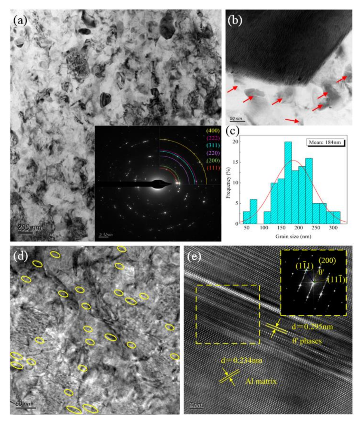
Figure 6 shows the microstructure of a CR-373K (1200 min) sample. More ultrafine grains were observed (Figure 6a). Figure 6a also shows the SAED along the <011> zone axis for the CR-373K (1200 min) samples (insert). The diffraction patterns developed into an approximately continuous ring, indicating that the orientation angle between adjacent structures increased and the grain size decreased. Notably, nanoscale grains with an average size of approximately 50 nm appeared (red arrows in Figure 6b) near some of the particles. According to statistics, the average grain size of the ultrafine grains was 184 nm (Figure 6c). The precipitates in the CR-373K (1200 min) samples are shown in Figure 6d,e. As shown in Figure 6d, densely distributed nanosized second-phase precipitates had formed at this stage as marked by yellow circles. The widths of the precipitates were approximately 2–6 nm and the lengths were 5–30 nm at the higher density of ~4.1 × 10¹⁵ m−2. Figure 6e shows the second-phase precipitates at a higher magnification and the strong 3/4{200}Al spots in the Fourier transform patterns. The <011> zone axis indicated that the precipitate was θ′-Al2Cu phase, which was consistent with the literature [22,23].
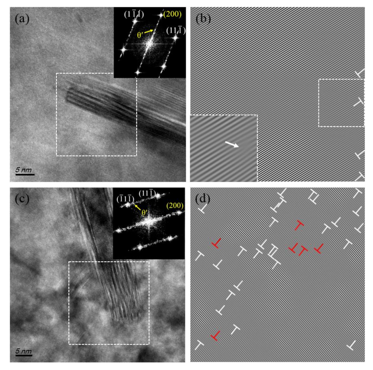
Figure 7 shows HRTEM micrographs and the corresponding inverse fast Fourier transform (IFFT) images from the regions containing θ′ phases from the CR-373K (1200 min) samples before (a,b) and after (c,d) tensile testing. As shown in Figure 7b, prior to tensile deformation, few dislocations existed around θ′ precipitates and no dislocations existed inside the precipitates. However, after tensile deformation dislocation piled up near the θ′ phase causing an increase in dislocation density (Figure 7d). In particular, the IFFT images showed that some dislocations (red mark in Figure 7d) were able to cut into the θ′-Al2Cu precipitates due to tensile deformation. The above experimental results showed that the θ′-Al2Cu precipitates could significantly increase the storage capacity of dislocations [24,25].

3.2.3. XRD Analysis

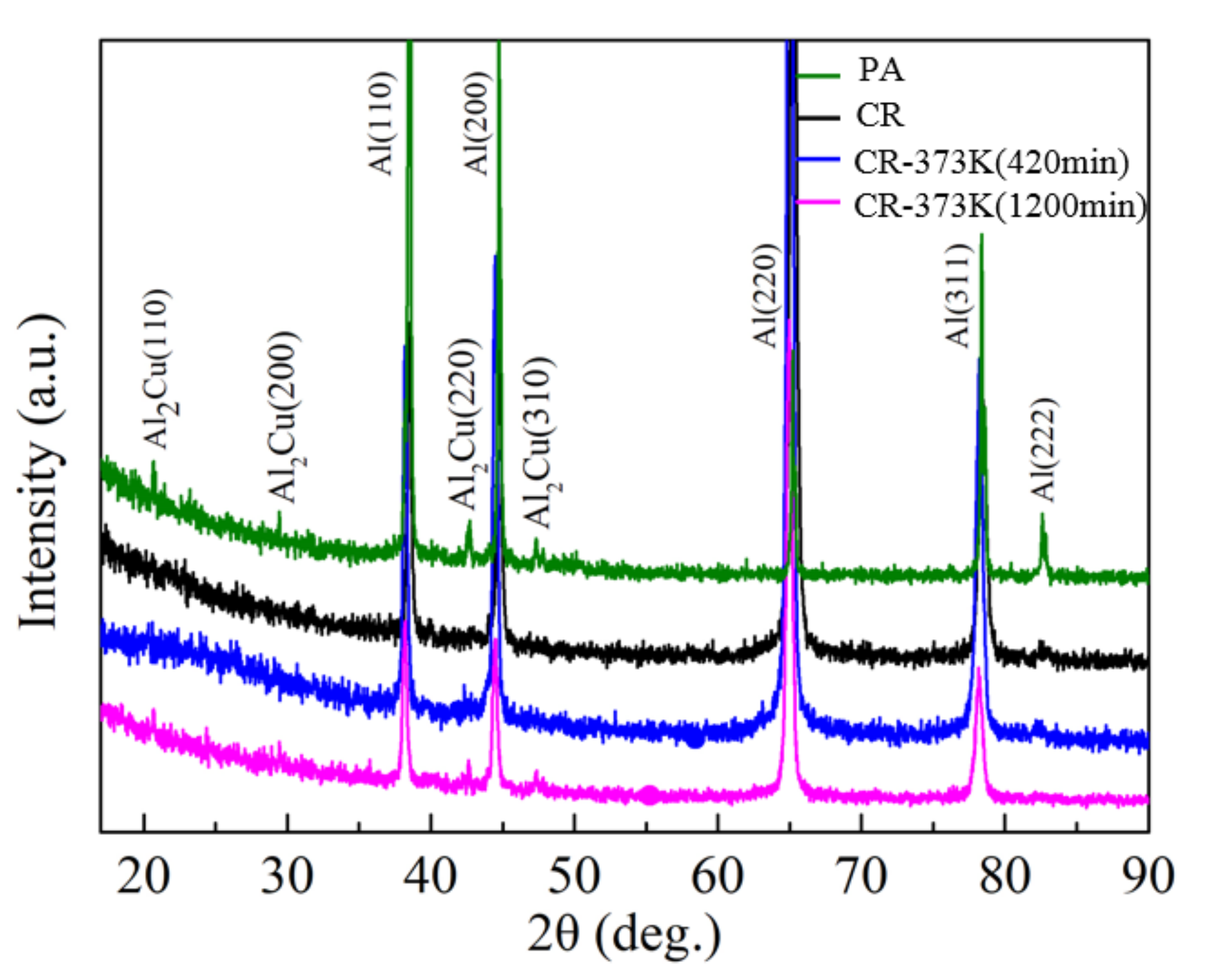
Based on the XRD patterns in Figure 8, the dislocation density of the CR and CR-373K samples was calculated by the Williamson–Hall method [15] and shown in Table 1. As shown in Table 1, the dislocation density of the CR-373K samples was reduced compared with that of the CR samples as a result of recovery caused by aging. For example, the dislocation density in the CR samples was 1.4 × 10¹⁵ m−2 while the dislocation density in the CR-373K (420 min) and CR-373K (1200 min) samples were 5.0 × 10¹⁴ m−2 and 3.9 × 10¹⁴ m−2, respectively. In addition, a θ′-Al2Cu precipitate peak with increased intensity was observed in the CR-373K samples (Figure 8). The relative intensities of the peaks in the CR-373K (1200 min) samples were higher than those in the CR-373K (420 min) and CR samples, indicating that the density of θ′-Al2Cu in the CR-373K (1200 min) sample was higher, which was consistent with the TEM results in Section 3.2.2.

3.2.4. Texture Evolution

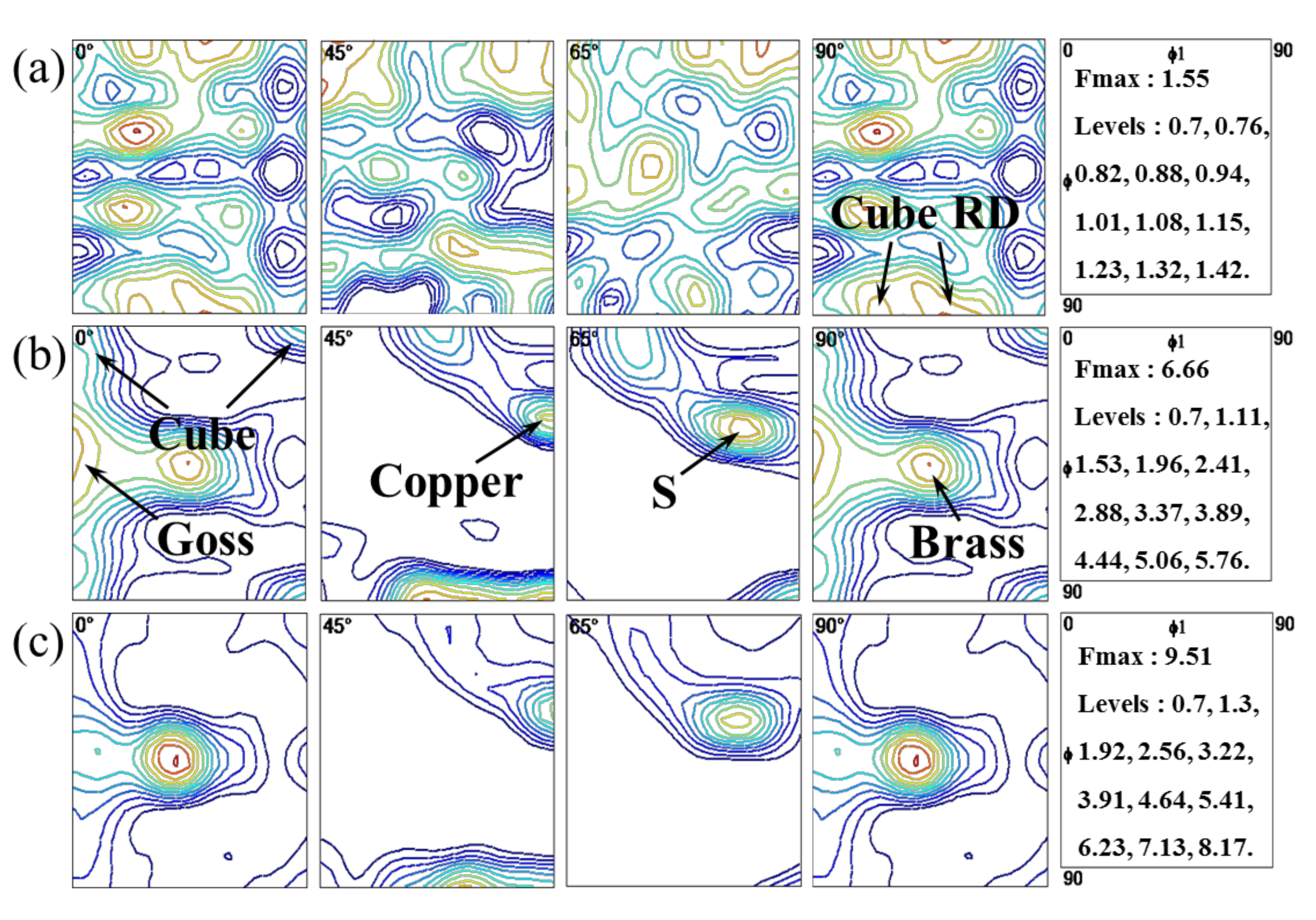
Figure 9 shows the ODFs for the PA, CR and CR-373K (1200 min) samples. The texture components and corresponding percentages are shown in Table 2. As shown in Figure 9 and Table 2, the rolling texture content of the PA samples was 15.17% and the random orientation accounted for a relatively large amount, which was 72.88%. In the CR sample, a typical β-fiber was formed from copper {112} <111> through S {123} <634> to brass {110} <112> [26]. Compared with those of the PA samples, the strength and percentage of the brass {110} <112>, S {123} <634> and copper {112} <111> textures in the CR samples increased significantly. The total rolling texture percentage was 59.16% and the random orientation proportion decreased to 23.15%. In addition, the strength and percentage of the cube {001} <100> and Goss {110} <001> textures increased slightly. The subsequent aging did not change the texture type of the CR samples. As shown in Figure 9c, the percentage of the rolled texture was 61.49% and the percentage of the other textures was 21.91%. Based on the above analysis of the texture type and percentage content, the Taylor factor was calculated using the following formula M A = Σ f i M i [27,28] (where fi and Mi are the percentage content and Taylor factor of different textures, respectively). Table 2 lists the Taylor factor values for the three samples. The Taylor factor value of the CR-373K (1200 min) samples was almost the same as that of the CR samples at 3.15 and 3.14, respectively; both were higher than the 3.04 value of the PA samples.
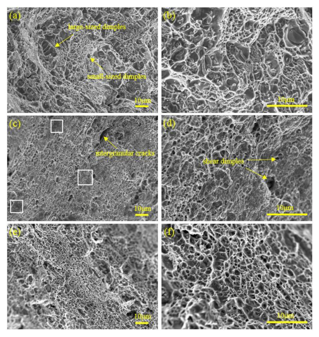
Figure 10 shows the SEM images for the fracture surfaces of the PA, CR and CR-AG373K (1200 min) samples. The PA sample exhibited a typical feature of ductile failure with large- and small-sized dimples over the entire fracture surface (Figure 10a,b). This indicated that the fracture mechanism of the PA samples was mainly a dimple-induced transgranular fracture. After fracture, smooth regions (white frame in Figure 10c) were detected on the CR sample in addition to the intergranular cracks and transgranular dimples. In addition, at higher magnifications, shallow shear dimples were also observed (yellow arrows in Figure 10d). Therefore, the fracture mechanism of the CR samples was also dominated by the dimple-induced transgranular fracture. As shown in Figure 10e,f, the fractographies of the CR-373K (1200 min) sample also consisted mainly of transgranular dimples. The above three samples were formed via ductile fracture mechanisms while the dimples in the CR and CR-373K (1200 min) samples were smaller than those in the PA samples due to their smaller grains.

4. Discussion

4.1. The Formation of Composite Nanostructures in the Al-Cu-Mn Alloy

For the CR-373K (1200 min) samples, a composite nanostructure composed of ultrafine grains, nanograins, a dislocation network structure and high density nanoscale precipitates was formed. The reasons for this formation were that the remaining T phase after ST could be used as a source of dislocations to emit dislocations during the deformation process [29] and that it could also promote the proliferation of dislocations or act as an obstacle to accumulate dislocations [21]. In addition, the T phase could also reduce the mean free path of dislocation movement and promote the conversion of dislocations to other structures. Moreover, there was a certain strain gradient between the T phase and the matrix during the deformation, which accelerated the evolution of the structure around the T phase. For example, in Figure 4b, nanoscale grains appeared near the T phase (as shown by the red arrow). In addition, when low-temperature aging was applied, many dislocations annihilated by meeting an opposite-sign dislocation, turning the highly entangled dislocation area into a dislocation network structure as shown in Figure 5a (white frame). The high density dislocations near the T phase formed nanograins through severe dislocation movements (such as gliding, accumulation and spatial rearrangement) during aging as shown in Figure 5a (red arrow). On the other hand, various types of defects formed around the T phase could accelerate the precipitation kinetics of the cold rolled samples during the postaging at a temperature lower than the 433 K of the traditional T6 treatment. For example, when the CR samples were aged at 373 K for 1200 min a large number of nanoprecipitates were formed at the expense of the supersaturated copper atoms (Figure 6d). In fact, dislocations were channels for the rapid diffusion of solute atoms at several orders of magnitude faster than the matrix, which was conducive to the nucleation of precipitates at the dislocations. Therefore, a mixed nanostructure consisting of dislocations and nanoprecipitates was observed as shown in Figure 6. In general, the interactions between various defects and solute atoms in the postaging process including recovery, partial recrystallization and precipitation ultimately led to the formation of the composite nanostructure in the Al-Cu-Mn alloy.

4.2. The Mechanism by Which Composite Nanostructures Influence Strength

The mechanical properties of the materials were determined by the microstructure. The contributions of composite nanostructures to strength were determined by the quantitative characterization of the dislocation density, grain size and characteristic parameters of precipitates in the long-aged structure. Generally, the YS of age-hardenable Al alloys could be calculated by the following equation [27]:
σ y = Δ g b + M A τ 0 + τ s + Δ τ d 2 + Δ τ p 2 1 / 2
where Δ g b is the grain boundary strengthening determined by the grain size, M A represents the Taylor factor that depends on the types and percentage of textures, τ 0 is the intrinsic critical resolved shear stress of pure Al that has a value of approximately 10 MPa, τ s is the solid solution strengthening that depends on the types and concentrations of solutes, Δ τ d is the dislocation strengthening from the dislocation density of the samples and Δ τ p is the precipitation strengthening attributed to the type, size and density of precipitates.
For the CR-373K (1200 min) samples containing composite nanostructures, the precipitation of a large number of nanoprecipitates introduced precipitation strengthening. Studies have shown [30] that deformed samples continuously consume solute atoms in supersaturated solid solutions during the subsequent aging to produce precipitates. When the peak-aged state is reached, the solid solution strengthening is almost removed. Figure 1a shows that the hardness of the deformed samples was the largest when they were aged at 373 K for 1200 min, which was when they could be considered to have reached the peak-aged state. Therefore, the contribution of solid solution strengthening to the strength of the CR-373K (1200 min) sample was approximately 0 MPa. On the other hand, Figure 6c shows that the average grain size of the CR-373K (1200 min) samples was 184 nm. At the same time, the dislocations in the CR-373K (1200 min) samples could still provide dislocation strengthening. Therefore, the YS of the CR-373K (1200 min) samples could be calculated with the following equation [16,25]:
σ y / CR 373 K   1200   min = Δ g b + M A τ 0 + Δ τ d 2 + Δ τ p 2 1 / 2 .
Generally, grain boundary strengthening is described by the Hall–Petch relationship [31]:
Δ g b = σ 0 + k 1 D 1 / 2
where σ 0 is the friction stress and k 1 D 1 / 2 is the grain boundary strengthening ( k 1 is the Hall–Petch slope and D is the effective grain size). In this paper, σ 0 and k 1 were approximately equal to 20 MPa and 0.04 MPa m−1/2, respectively [31]. Therefore, the calculated value for the CR-373K (1200 min) samples was 113.26 MPa.
In this paper, the classic Bailey–Hirsch relationship was used to determine how dislocation strengthening affects the YS [25]:
Δ τ d = α Gb ρ 1 / 2
where α is a constant with a value of 0.27, G is the shear modulus of the aluminum alloy that has a value of 26.2 GPa and b is the Burgers vector, whose magnitude is equal to 0.286 [17]. According to Equation (4), Δ σ d for the CR-373K (1200 min) samples was 39.95 MPa.
Precipitation strengthening is the most important strengthening mechanism for age-hardenable Al alloys and depends on the size, distribution and spacing of the precipitates. Δ σ P can be simply expressed by the following equation [27,28]:
Δ τ P = 0.85 Gbln x / b / 2 π l x
where the average diameter (x) and spacing (l) of the precipitated phases in the CR-373K (1200 min) samples were estimated from the HRTEM and TEM images and were equal to 16 nm and 44 nm, respectively. Therefore, the value of Δ σ p for the CR-373K (1200 min) samples was 140.12 MPa based on Equation (5).
The YS of the CR-373K (1200 min) samples was calculated to be 603.72 MPa from Equation (2) and the calculated results were close to the experimental values of 564 MPa. This indicates that the increase in precipitation strengthening and grain boundary strengthening in the CR-373K (1200 min) samples was higher than the decrease in solid solution strengthening and dislocation strengthening. Therefore, the above results indicated that the composite nanostructures formed in the CR-373K (1200 min) samples contributed to the improvement in strength.

4.3. The Mechanism by Which Composite Nanostructures Influence Ductility

The elongation (Ef) of metallic materials reflected the ability of the samples to accumulate dislocations during the tensile process including uniform elongation (Eu) and local elongation (E1). Among them, Eu reflected the dislocation accumulation ability of the alloy before the peak Stress. At this stage, the tensile samples mainly underwent uniform plastic deformation. El reflected the strain increments after the peak stress where the plastic deformation at this stage was mainly concentrated in a certain position [25]. As shown in Figure 2a, compared with that of the CR samples, the Eu of the CR-373K (1200 min) samples was significantly increased (~124%) while the difference in E1 was not significant. The above phenomenon could be attributed to: (i) a reduction in dislocation density (Table 1), (ii) high density nanoscale precipitates (Figure 6d) and (iii) a large number of ultrafine grains (Figure 6a). Compared with the CR samples, the reduction in the dislocation density in the CR-373K (1200 min) samples reclaimed a part of the lattice space of the matrix, which could accumulate more dislocations during tensile deformation thereby improving the work-hardening ability (Figure 2b). On the other hand, it could be inferred from the high density dislocations near the precipitates of the CR-373K (1200 min) samples after tensile deformation that the regularly arranged nanoscale precipitates produced stronger resistance than dislocation slip, which made them jam near the precipitates thus promoting crack initiation by greatly increasing the resistance. Therefore, compared with the CR samples, the CR-373K (1200 min) samples could accumulate more dislocations during tensile deformation, which greatly improved Eu. In addition, the recovery and the growth of the grains could also increase the Eu of the material but the effect could not play a leading role. At the same time, as shown in Figure 10e, the fracture surface consisted of fine dimples and the depth of the dimples was larger than that of the CR samples (Figure 10f) indicating that the composite nanostructure in the CR-373K (1200 min) samples could absorb more deformation energy before the final fracture thus showing a higher tensile ductility.

5. Conclusions

In summary, high strength and good ductility were achieved in the UFG/NG Al-Cu-Mn alloy through cold rolling and subsequent aging. The main conclusions are as follows:
(1)
The remaining T phase after ST effectively promoted the accumulation of dislocations during deformation. The high density dislocations promoted the formation of nanosized precipitates and ultrafine grains/nanograins in the postaging process, which significantly improved the strength of the CR samples.
(2)
Optimization of the postaging process improved the ductility of the CR samples. The nanoscale precipitated phases generated during the low-temperature aging not only compensated for a decrease in strength caused by a reduction in the dislocation density but also improved the work-hardening ability by pinning and accumulating dislocations. At the same time, the reduction in the dislocation density also increased the work-hardening rate.
(3)
Tensile fractures of the CR-373K (1200 min) samples mainly occurred via transgranular fractures induced by dimples.

Author Contributions

Conceptualization: K.F. and M.Y.; methodology: K.F. and S.L.; formal analysis: K.F., L.Y. and M.Y.; writing (original draft preparation): K.F.; writing (review and editing): K.F.; and supervision: M.Y., S.-l.L. and B.L. All authors have read and agreed to the published version of the manuscript.

Funding

This research was funded by the Engineering Research Center Project from the Department of Education of Guizhou Province (contract number [2017]016) and the Program Foundation for Talents of Guizhou University (grant number [2017]02).

Acknowledgments

The author states that there is no conflict of interest in the publication of this paper.

Conflicts of Interest

The funders had no role in the design of the study; in the collection, analyses, or interpretation of data; in the writing of the manuscript; or in the decision to publish the results.

References

  1. Ivanov, K.V.; Ovcharenko, V.E. Structural features of ultrafine-grained aluminum processed through accumulative roll bonding providing improved mechanical properties and thermal stability. Mater. Sci. Eng. A 2020, 775, 138988. [Google Scholar] [CrossRef]
  2. Yu, H.L.; Su, L.; Lu, C.; Tieu, K.; Li, H.; Li, J.; Godbole, A.; Kong, C. Enhanced mechanical properties of ARB-processed aluminum alloy 6061 sheets by subsequent asymmetric cryorolling and ageing. Mater. Sci. Eng. A Struct. Mater. Prop. Microstruct. Process. 2016, 674, 256–261. [Google Scholar] [CrossRef] [Green Version]
  3. Howeyze, M.; Eivani, A.R.; Arabi, H.; Jafarian, H.R. Effects of deformation routes on the evolution of microstructure, texture and tensile properties of AA5052 aluminum alloy. Mater. Sci. Eng. A 2018, 732, 120–128. [Google Scholar] [CrossRef]
  4. Braga, D.P.; Camilo-Magalhes, D.C.; Kliauga, A.M.; Della-Rovere, C.A.; Sordi, V.L. Microstructure, mechanical behavior and stress corrosion cracking susceptibility in ultrafine-grained Al-Cu alloy. Mater. Sci. Eng. A 2020, 773, 138865. [Google Scholar] [CrossRef]
  5. Okeke, U.; Yilmazer, H.; Sato, S.; Boehlert, C.J. Strength enhancement of an aluminum alloy through high pressure torsion. Mater. Sci. Eng. A Struct. Mater. Prop. Microstruct. Process. 2019, 760, 195–205. [Google Scholar] [CrossRef]
  6. Zha, M.; Li, Y.; Mathiesen, R.H.; Bjørge, R.; Roven, H.J. Microstructure evolution and mechanical behavior of a binary Al-7Mg alloy processed by equal-channel angular pressing. Acta Mater. 2006, 84, 42–54. [Google Scholar] [CrossRef]
  7. Wang, Y.; Chen, M.; Zhou, F.; Ma, E. High tensile ductility in a nanostructured metal. Nature 2002, 419, 912–915. [Google Scholar] [CrossRef]
  8. Zhao, Y.H.; Bingert, J.F.; Liao, X.Z.; Cui, B.Z.; Han, K.; Sergueeva, A.V.; Amiya, K. Simultaneously Increasing the Ductility and Strength of Ultra-Fine-Grained Pure Copper. Adv. Mater. 2006, 18, 2949–2953. [Google Scholar] [CrossRef]
  9. Dao, M.; Lu, L.; Shen, Y.F.; Suresh, S. Strength, strain-rate sensitivity and ductility of copper with nanoscale twins. Acta Mater. 2006, 54, 5421–5432. [Google Scholar] [CrossRef]
  10. Lu, L.; Shen, Y.; Chen, X.; Qian, L.; Lu, K. Ultrahigh strength and high electrical conductivity in copper. Science 2004, 304, 422–426. [Google Scholar] [CrossRef] [Green Version]
  11. Horita, Z.; Ohashi, K.; Fujita, T.; Kaneko, K.; Langdon, T.G. Achieving High Strength and High Ductility in Precipitation-Hardened Alloys. Adv. Mater. 2005, 17, 1599–1602. [Google Scholar] [CrossRef]
  12. Cheng, S.; Ma, E. Simultaneously Increasing the Ductility and Strength of Nanostructured Alloys. Adv. Mater. 2006, 18, 2280–2283. [Google Scholar]
  13. Bunge, H.J.; Morris, P.R. Texture Analysis in Materials Science: Mathematical Methods; Butterworths: London, UK, 1982. [Google Scholar]
  14. Tang, J.G.; Zhang, X.M.; Deng, Y.L.; Du, Y.X.; Chen, Z.Y. Texture decomposition with particle swarm optimization method. Comput. Mater. Sci. 2006, 38, 395–399. [Google Scholar] [CrossRef]
  15. Williamson, G.K.; Hall, W.H. X-ray line broadening from filed aluminum and wolfram. Acta Metall. 1953, 1, 22–31. [Google Scholar] [CrossRef]
  16. Wang, Z.; Chen, M.; Jiang, H.; Li, H.; Li, S. Effect of artificial ageing on strength and ductility of an Al-Cu-Mg-Mn alloy subjected to solutionizing and room-temperature rolling. Mater. Charact. 2020, 165, 110383. [Google Scholar] [CrossRef]
  17. Seidman, D.N.; Marquis, E.A.; Dunand, D.C. Precipitation strengthening at ambient and elevated temperatures of heat-treatable Al(Sc) alloys. Acta Mater. 2002, 50, 4021–4035. [Google Scholar] [CrossRef]
  18. Vulf, B.K.; Chernov, M.N. Influence of ternary intermetallic compounds on the heat resistance of deformed aluminium alloys (in Russian). Tsvet. Metall. 1960, 2, 147–152. [Google Scholar]
  19. Polesya, A.F.; Kovalenko, V.V. Phase diagram of rapidly solidified Al–Cu-Mn alloys. Russ. Metall. 1970, 1, 114–117. [Google Scholar]
  20. Feng, Z.Q.; Yang, Y.Q.; Huang, B.; Li, M.H.; Chen, Y.X.; Ru, J.G. Crystal substructures of the rotation-twinned T (Al 20 Cu 2 Mn 3) phase in 2024 aluminum alloy. J. Alloys Compd. 2014, 583, 445–451. [Google Scholar] [CrossRef]
  21. Cheng, S.; Zhao, Y.H.; Zhu, Y.T.; Ma, E. Optimizing the strength and ductility of fine structured 2024 Al alloy by nano-precipitation. Acta Mater. 2007, 55, 5822–5832. [Google Scholar] [CrossRef]
  22. He, H.; Yi, Y.; Huang, S.; Zhang, Y. Effects of cold predeformation on dissolution of second-phase Al 2 Cu particles during solution treatment of 2219 Al-Cu alloy forgings. Mater. Charact. 2018, 135, 18–24. [Google Scholar] [CrossRef]
  23. Rakhmonov, J.; Liu, K.; Pan, L.; Breton, F.; Chen, X.G. Enhanced mechanical properties of high-temperature-resistant Al-Cu cast alloy by microalloying with Mg. J. Alloys Compd. 2020, 827, 154305. [Google Scholar] [CrossRef]
  24. Xu, P.; Luo, H. Improving the ductility of nanostructured Al alloy using strongly textured nano-laminated structure combined with nano-precipitates. Mater. Sci. Eng. A 2016, 675, 323–337. [Google Scholar] [CrossRef]
  25. Li, H.; Chen, P.; Wang, Z.; Zhu, F.; Song, R.; Zheng, Z. Tensile properties, microstructures and fracture behaviors of an Al-Zn-Mg-Cu alloy during ageing after solution treating and cold-rolling. Mater. Sci. Eng. A 2019, 742, 798–812. [Google Scholar] [CrossRef]
  26. Gu, J.; Wang, X.; Bai, J.; Ding, J.; Williams, S.; Zhai, Y.; Liu, K. Deformation microstructures and strengthening mechanisms for the wire+arc additively manufactured Al-Mg4.5Mn alloy with inter-layer rolling. Mater. Sci. Eng. A 2018, 712, 292–301. [Google Scholar] [CrossRef]
  27. Starink, M.J.; Wang, S.C. A model for the yield strength of overaged Al–Zn–Mg–Cu alloys. Acta Mater. 2003, 51, 5131–5150. [Google Scholar] [CrossRef] [Green Version]
  28. Song, R.; Wei, H.; Zheng, Z.; Wang, Z.; Fang, B. Effects of re-ageing treatment on microstructure and tensile properties of solution treated and cold-rolled Al-Cu-Mg alloys. Mater. Sci. Eng. A 2016, 650, 254–263. [Google Scholar]
  29. Wu, X.; Tao, N.; Hong, Y.; Xu, B.; Lu, J.; Lu, K. Microstructure and evolution of mechanically-induced ultrafine grain in surface layer of AL-alloy subjected to USSP. Acta Mater. 2002, 50, 2075–2084. [Google Scholar] [CrossRef]
  30. Ma, K.; Wen, H.; Hu, T.; Topping, T.D.; Isheim, D.; Seidman, D.N.; Lavernia, E.J.; Schoenung, J.M. Mechanical behavior and strengthening mechanisms in ultrafine grain precipitation-strengthened aluminum alloy. Acta Mater. 2014, 62, 141–155. [Google Scholar] [CrossRef]
  31. Hansen, N. Hall-Petch relation and boundary strengthening. Scr. Mater. 2004, 51, 801–806. [Google Scholar] [CrossRef]
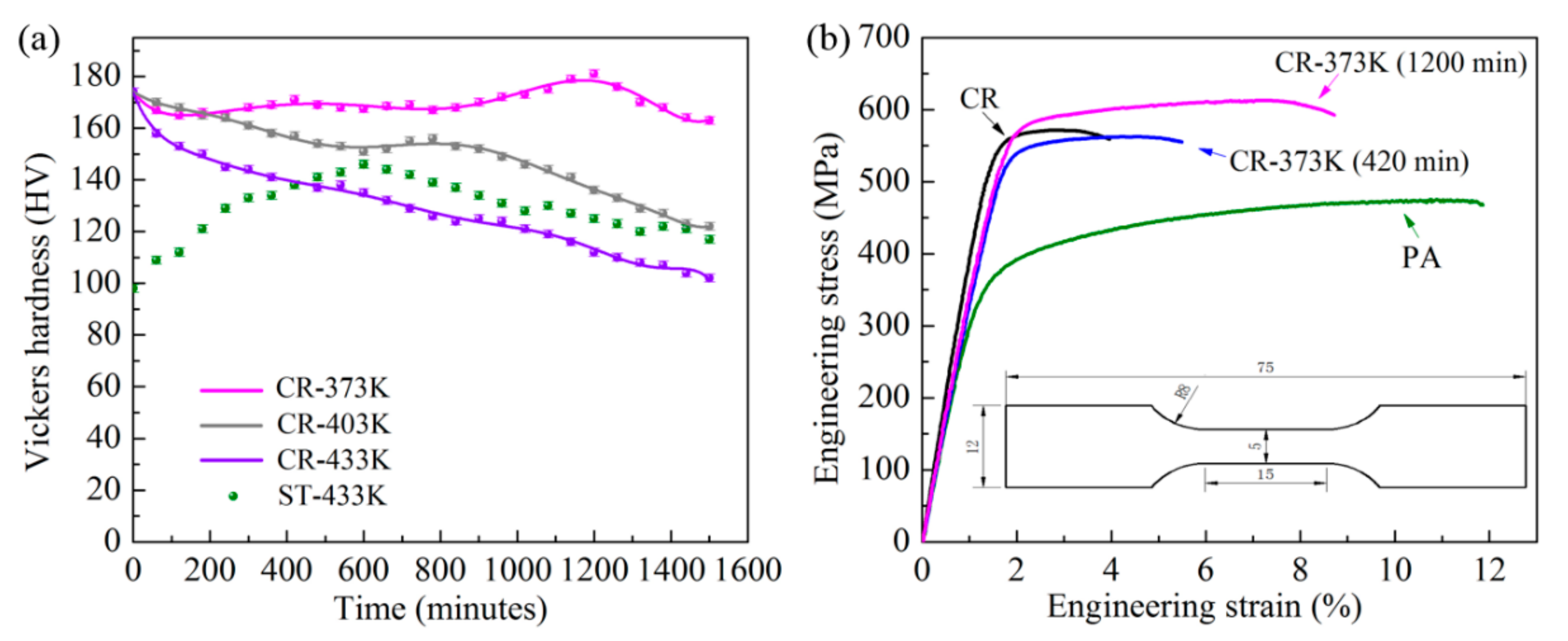
Figure 1. (a) Hardness curve of ST samples aged at 433 K for up to 1500 min and cold rolled (CR) samples aged at 373 K, 403 K and 433 K for up to 1500 min; (b) engineering stress-strain curves of the alloy in different states.
Applsci 10 08109 g001
Figure 2. (a) The Ef, Eu and El values and (b) the normalized work-hardening rate-true stress curves of the alloy in different states.
Applsci 10 08109 g002
Figure 3. Optical microstructures of the alloys: (a,b) PA; (c,d) CR; (e,f) CR-373K (1200 min).
Applsci 10 08109 g003
Figure 4. (a) Bright-field TEM micrograph of CR samples showing typical dislocation cell structures in the aluminum matrix; (b) corresponding high-magnification TEM micrograph showing the high dislocation density and subgrain morphologies and boundaries; (c) EDS spectra for the large rod-like dispersoids in (b); (d) the SAED pattern with the <011> zone axis.
Applsci 10 08109 g004
Figure 5. (a) Bright-field TEM micrograph of CR-373K (1200 min) samples; (b) high-resolution transmission electron microscopy (HRTEM) micrograph of the white frame in (a) and corresponding Fourier transform patterns of the red frame; (c) the SAED pattern with the <011> zone axis.
Applsci 10 08109 g005
Figure 6. TEM micrograph for the CR-373K (1200 min) samples: (a) Bright-field TEM image showing ultrafine grains (inset is the SAED pattern taken along the <011> zone axis); (b) nanoscale grains; (c) statistical grain size distribution; (d) bright-field TEM image of the precipitates; (e) HRTEM and Fourier transform patterns of a typical precipitate.
Applsci 10 08109 g006
Figure 7. HRTEM micrograph of the CR-373K (1200 min) samples before (a) and after fracture (c); inset is the Fourier transform patterns taken from the white wireframe; (b) corresponding IFFT pattern of (a) with lower dislocation density (marked by “T”); (d) corresponding IFFT pattern of (c) with higher dislocation density. Red dislocations “T” represent the introduction of dislocations into the θ′ precipitates.
Applsci 10 08109 g007
Figure 8. XRD patterns of the Al-Cu-Mn alloy in the CR and CR-373K conditions.
Applsci 10 08109 g008
Figure 9. Orientation distribution functions (ODFs) of the Al-Cu-Mn alloy: (a) PA; (b) CR; (c) CR-373K (1200 min).
Applsci 10 08109 g009
Figure 10. SEM fractograph for tensile test specimens of the alloy: (a,b) PA; (c,d) CR; (e,f) CR-373K (1200 min).
Applsci 10 08109 g010
Table 1. Microcrystallite sizes, microstrains and dislocation densities of the CR and CR-373K samples.
Alloy Sampled/nm ε / % ρ / m 2
CR160.181.4 × 1015
CR-373K (420 min)510.215.0 × 1014
CR-373K (1200 min)710.233.9 × 1014
Table 2. Texture components (%) and average Taylor factors for peak aging (PA), CR and CR-373K (1200 min) samples.
Alloy SampleCube (2.45)Goss (2.45)Brass (3.17)S (3.33)Copper (3.7)Random (3.07)Rolling TextureMA
PA5.256.135.835.424.4972.8815.173.04
CR6.8910.8011.5636.6710.9323.1559.163.14
CR-373K (1200 min)6.5010.1015.1933.7712.5321.9161.493.15
Publisher’s Note: MDPI stays neutral with regard to jurisdictional claims in published maps and institutional affiliations.