Abstract
The present work deals with natural and whirl frequency analysis of a porous functionally graded (FG) rotor–bearing system using the finite element method (FEM). Stiffness, mass and gyroscopic matrices are derived for porous and non-porous FG shafts by developing a novel two-noded porous FG shaft element using Timoshenko beam theory (TBT), considering the effects of translational inertia, rotatory inertia, gyroscopic moments and shear deformation. A functionally graded shaft whose inner core is comprised of stainless steel (SS) and an outer layer made of ceramic (ZrO2) is considered. The effects of porosity on the volume fractions and the material properties are modelled using a porosity index. The non-linear temperature distribution (NLTD) method based on the Fourier law of heat conduction is used for the temperature distribution in the radial direction. The natural and whirl frequencies of the porous and non-porous FG rotor systems have been computed for different power law indices, volume fractions of porosity and thermal gradients to investigate the influence of porosity on fundamental frequencies. It has been found that the power law index, volume fraction of porosity and thermal gradient have a significant influence on the natural and whirl frequencies of the FG rotor–bearing system.
1. Introduction
An important aspect to take into consideration for a superior structural performance is the material strength of the system. Traditional composite materials are impotent when they are subjected to thermo-mechanical loading, due to inter-laminar stresses which cause the de-lamination of layers. Generally, metals are preferred because of their high strength and toughness [1]. However, at high temperatures, the strength of the metal drastically deteriorates. On the other hand, ceramics are heat resistant; however, their applications are restricted due to their low toughness. The development of a new class of composites, functionally graded materials (FGMs), mitigated the problems of de-bonding, de-lamination and residual stresses in fibre-reinforced composites at elevated temperature, while making use of the advantages of both metal and ceramic material properties. FGM is an inhomogeneous micromechanical composite typically made from different phases of metal and ceramic material constituents. The volume fraction of constituent materials is arranged in the desired direction based on material laws for smooth and continuous change from one layer to another.
The term FGM was coined by a group of Japanese scientists in the mid-1980s. There are numerous types of methods based on material applications to fabricate FGMs—they include plasma spraying, chemical vapour deposition, physical vapour deposition, slurry dipping, electroplating, sintering, combustion synthesis, centrifugal casting, tape casting, hot pressing, powder metallurgy, etc. Suresh and Mortensen [2] and Miyamoto et al. [3] discussed some of the manufacturing processes of functionally graded materials. The initial functionally graded materials were made for the aerospace industry, as the highest temperature of the surface of spacecrafts is estimated to reach as high as 2100 K; hence, the material used on the surface should withstand that high temperature [4]. Moreover, on account of wide range of applications in many other industries, such as automotive, electronics, biomedical, marine, defence and construction, functionally graded materials have become a topic of interest for many researchers. Most of the previous works have reported on the dynamic characteristics of beams. Since the modelling of the FG shaft in the present work is based on Timoshenko beam theory with rotating effects, the literature review is arranged around the dynamic analysis of FG beams, FG rotors and then porous FG beams and rotors.
Many investigations were executed to analyse FG structures, and excellent review papers are reported in the literature [5,6,7]. Liu et al. [8] developed a shell element to analyse the nonlinear response of FG structures. Liu and Jeffers [9] performed an isogeometric analysis of FG sandwich plates based on layer wise displacement theory. Simsek [10] investigated a static analysis of a functionally graded simply supported beam under a uniformly distributed load by the Ritz method, using Timoshenko and higher order shear deformation beam theories. The fundamental frequency of FG beams using classical, first order and different higher order shear deformation theories for different boundary conditions was analysed [11]. Aydogdu and Taskin [12] performed a free vibration analysis of simply supported FG beams using parabolic shear deformation beam theory, classical beam theory and exponential shear deformation beam theory. Pydah and Sabole [13] performed a static analysis of an FG bi-directional circular beam based on Euler–Bernoulli theory. The free vibration analysis of Euler and Timoshenko FG beams using the Rayleigh–Ritz method subjected to different boundary conditions is investigated by Pradhan and Chakraverty [14]. Li et al. [15] developed a beam model for the accurate analysis of FG beams based on a material-based higher-order shear theory.
Rotor–bearing systems play a crucial role in the mechanical industry, and several researchers analysed rotor–bearing systems based on various models. Dimentberg [16] examined viscous and hysteretic internal damping of a rotating shaft. Ruhl and Booker [17] developed a finite element model of a turbo-rotor system by including the effects of translational kinetic energy and elastic bending energy. Nelson and McVaugh [18] generalised the Ruhl’s element by including the effects of rotatory inertia, gyroscopic moments and axial load. Extending this work, Nelson [19] developed a finite shaft element using Timoshenko beam theory by including the effects of transverse shear deformation. The works reported above are related to steel or uniform shafts. Very few works reported on the dynamic analysis of an FG rotor–bearing system. Gayen and Roy [20], based on Timoshenko beam theory (TBT), presented a work on the vibration and stability analysis of a functionally graded spinning shaft using three node beam elements. Bose and Sathujoda [21] performed natural frequency analysis of a functionally graded rotor system using a three-dimensional element, modelled in ANSYS (ANSYS 18.0, ANSYS, Canonsburg, PA, USA). As FGMs have an extensive variety of applications, it is important to consider the effect of temperature on FG structures and rotors. Recently, Mahi et al. [22] investigated the temperature-dependent free vibration analysis of FG beams with general boundary conditions. The thermo-mechanical buckling and non-vibration analysis of FG beams on a nonlinear elastic foundation are examined [23]. Zhang [24] analysed the thermal post buckling and nonlinear vibration behaviour of functionally graded beams based on the concept of physical neutral surfaces, von Karman strain–displacement relationships and higher order shear deformation theory. Kiani and Eslami [25] analysed the thermal buckling of FG beams. Very few works are reported to investigate the effect of temperature on FG rotors. The effect of thermal gradients on the natural frequencies of functionally graded rotor–bearing systems is investigated by Bose and Sathujoda [26]. The natural frequency of the FG rotor–bearing system for different temperature gradients is analysed by Gayen et al. [27]. Gayen et al. [28] also analysed the influence of temperature gradients on the whirl frequencies of a cracked rotor.
Amid all of the fabrication techniques, sintering is one of the ways to fabricate an FGM, but due to huge differences in the solidification temperatures of material constituents, micro voids and porosities are formed within the inter-layers of FGM while fabricating with this technique [29]. Wattanasakulpong et al. [30] deduced that porosities are also formed when a functionally graded material is fabricated using a multi-step sequential infiltration technique. The density and strength of an FGM are reduced due to the presence of porosities in the structure of FGM. Since the formation of porosities is inevitable while fabricating, the effect of porosity has become extremely prominent for analysing an FG system. Akbas [31] explored the forced vibration analysis of FG porous deep beams under dynamic loads. Ebrahimi and Jafari [32] investigated the vibration analysis of porous FG beams subjected to various thermal loadings based on higher order shear deformation theory carried out by utilising the Navier solution method. Ebrahimi and Mokhtari [33] presented a transverse vibration analysis of rotating porous functionally graded beams using the differential transform method. Atmane et al. [34] presented a free vibration analysis of thick, porous, functionally graded beams resting on elastic foundations using efficient shear and normal deformation beam theory. Wattanasakulpong and Chaikittiratana [35] investigated the flexural vibration analysis of a porous functionally graded beam using Timoshenko beam theory. Wattanasakulpong and Ungbhakorn [36] investigated the linear and nonlinear vibration analysis of elastically end-restrained FG beams with different porosities. Researchers have been analysing FG rotor systems with crack defects. A vibration analysis of an FG rotor–bearing system whose FG shaft had a transverse crack and a surface crack was performed using finite element formulation [27,28]. Sathujoda et al. [37] investigated the natural and whirl frequencies of a corroded FG rotor–bearing system using the finite element method (FEM). Even though a few works on the natural frequency analysis of cracked and corroded FG rotor systems are available [27,28,37] in the literature, to the best of the authors’ knowledge, research on the dynamic analysis of a porous FG rotor system is rarely found. Recently, an attempt was made by Bose and Sathujoda [38] to analyse the natural frequencies of a porous FG rotor–bearing system without thermal effects using ANSYS three-dimensional finite elements. However, this is an approximate analysis without any thermal effects and the model is not suitable for time dependent steady-state and transient dynamic vibration analyses. Since FG rotors are generally subjected to elevated temperatures to make use of FG material properties, a comprehensive and accurate study of the natural and whirl frequencies of a porous FG rotor system using efficient modelling is required, which is addressed in the present work.
This literature review reveals that the research on the vibration analysis of porous FG rotor–bearing systems is extremely limited. Since the porosity affects the dynamic characteristics of an FG rotor system, it is important to analyse the dynamic properties, such as natural and whirl frequencies, to avoid rotor failures. Our main interest in the present work is to investigate the natural and whirl frequencies of a porous FG rotor–bearing system using a novel two-node porous FG shaft element. Dimensionless natural frequencies and whirl frequencies are computed for different power law indices (k) and volume fractions of porosity (α) at different temperature gradients (∆T).
2. Materials and Methods
Material modelling of a porous FG shaft is reported in this section. Detailed descriptions of the non-linear temperature distribution (NLTD), as well as the power law gradation of nonporous and porous FG shafts, are presented in Section 2.1, Section 2.2 and Section 2.3, respectively.
Material gradation is divided into three categories: continuously graded microstructure, discretely graded microstructure and multi-phase graded microstructure [39]. Generally, in FGM, material properties (thermal conductivity K, Young’s modulus E, density and Poisson’s ratio) are diversified along the gradation direction. The radial direction is considered the gradation direction in the case of circular FG shafts; as the precise details of the graded microstructure of FGM are obscured, the volume fraction of different phases is used for material gradation. The distribution of metal and ceramic phases along the radial direction of the FG shaft is represented in Figure 1. The properties of FGM must be position and temperature dependent for a precise model of the FG shaft. The position dependency of material properties can be achieved by the Voigt model [40], which is a simple rule for mixtures of composites. The material properties of a specific layer Pl are expressed as in Equation (1).
where and are the material properties of metal and ceramic; and are the volume fractions of metal and ceramic of the respective layers. The temperature dependency of material properties given by Touloukian [41] can be expressed as a non-linear function of temperature, as shown in Equation (2). Although there are many other non-linear variations in the rotating systems [42,43], the non-linear gradation of material properties and non-linear temperature distribution are considered in the present work.
where T is temperature in Kelvin, and , , , and are coefficients of temperature that are different for different material constituents. Reddy and Chin [44] listed these coefficients and they are represented in Table 1.
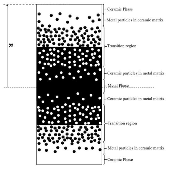
Figure 1.
Distribution of metal and ceramic phases along the radial direction of a functionally graded (FG) shaft.

Table 1.
Thermal coefficients of the constituent materials of functionally graded materials (FGMs).
2.1. Non-Linear Temperature Distribution (NLTD)
It is presumed that the temperature is varied only along the radial direction of the shaft. The temperature variation in a hollow cylinder at any radial distance r is given by a 1-D Fourier heat conduction equation, as shown in Equation (3). and are inner and outer temperatures of a cylinder, while are the innermost and outermost radii of the cylinder, respectively, is thermal conductivity at radius r.
Considering that there is no heat generation and, for boundary conditions, gives the non-linear temperature distribution , Equation (4) is the solution of Equation (3). Only the first seven terms of a polynomial series are considered as the solution [45]. and
2.2. Power Law Gradation of Non-Porous FG Shaft
There are various gradation laws such as the power law, sigmoidal law and exponential law for material gradation. Amongst these gradation laws, the power law is the most widely used and is the simplest for controlling the gradation of material properties. As FGM is especially made for high-temperature conditions, it is considered that material properties vary nonlinearly with temperature (T). Thus, NLTD is always used alongside the power law. For an FG shaft with a circular cross-section, the power law is expressed as in Equation (5) [28].
where P(r,T) represents the varying material properties along with the radius. Ri and Ro represent the inner and outer radius of the shaft, r is the radial coordinate of the shaft and k is the power law index. The value of k can range from 0 to ∞.
2.3. Material Gradation of Porous FG Shaft
The porosity of an FG system can be classified into even porosity and uneven porosity. The even distribution of the porosities is represented in Figure 2. The distribution of porosity in an FG rectangular beam is available in the literature [36]; however, in the present work, porosities are distributed in FG circular shafts. An FG shaft whose inner core is comprised of stainless steel (SS) and an outer layer made of ceramic (ZrO2) is considered to have porosities that are evenly distributed within the cross-section of the shaft. Typically, these porosities are formed in the shaft during the process of fabrication. Due to these porosities, the material properties of layer are modified as shown in Equation (6).
where α () is the porosity volume fraction for the porous FG shafts and for the FG shaft without porosity. Here, in Equation (6), , and , represent material properties and volume fraction of metal and ceramic. The sum of the volume fractions of metal and ceramic is shown in Equation (7).

Figure 2.
Even distribution of porosity in an FGM.
Since the FG shaft consists of porosities, the material properties of the FG shaft also depend on the volume fraction of the porosity. Hence, the modified power law for even porosity is expressed as shown in Equation (8).
The material properties such as Young’s modulus, Poisson’s ratio and the material density of imperfect FGM with an even porosity are expressed as shown in Equations (9a)–(9c).
where represents the inner radius, represents the outer radius of the shaft, r is the radial coordinate of the shaft and k is the power law index.
A porous, functionally graded rotor–bearing system is considered in the present work. The rotor shaft is made of an FGM; it is assumed that porosity is evenly distributed in the FG shaft. The disc, made of uniform steel, is precisely located at the mid-span of the FG shaft. The ends of the shaft are mounted on linear bearings. Python (IDLE Python 3.6.1, 64-bit, Python Software Foundation, Wilmington, DE, USA) code is developed to assign the material properties using the power law and NLTD. Finite element modelling of the porous FG shaft element provides the novelty of the current research work, and is described in Section 3.
3. Finite Element Modelling of Porous FG Rotor–Bearing System
The finite element formulations have been developed using Timoshenko beam theory (TBT) for natural frequency analysis of porous and nonporous FG rotor systems. A two-noded porous FG shaft element stiffness and mass matrices are derived in this work, and is, to the best of the authors’ knowledge, not available in the literature. The effects of rotatory inertia, gyroscopic moments, elastic bending energy, translational kinetic energy, and transverse shear deformation are included in shaft element modelling. A typical FG rotor–bearing system is shown in Figure 3a. A uniform steel disc is located precisely at the mid-span of the shaft and the ends of the shaft are supported on linear bearings. The component equations of motion of the FG rotor system are discussed in the following Sections (Section 3.1, Section 3.2 and Section 3.3).
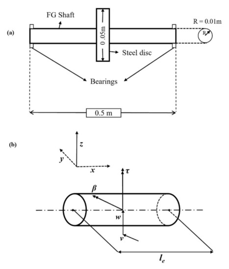
Figure 3.
(a) An FG rotor–bearing system. (b) A porous FG shaft element.
3.1. Finite Porous FG Shaft Element
The FG shaft was divided into ten finite elements. A two-node FG shaft element was developed based on Timoshenko beam theory. Each node of the element was considered to have four degrees of freedom (two translational and two rotational) as shown in Figure 3b. As the analysis was performed for natural bending frequencies, which are appropriate in the case of a Jeffcott rotor supported on linear bearings in transverse directions, the axial translational degree of freedom was not considered. The equation of motion of the uniform shaft element is mentioned in the work of Nelson and McVaugh [16]. The equation of motion of the porous FG shaft element (Equation (10)) can be developed by the application of Hamilton’s extended principle and by using the equation of energy and work functions discussed in [19]. However, in the present work, the individual matrices are also the functions of the volume fraction of porosity, the radial variation in the material properties and the temperature gradients, unlike the uniform shaft element.
The coefficient matrices are
Equation (10) represents the elemental equation of motion of a porous FG shaft. is the spin speed of the shaft in . is the elemental stiffness matrix, is the elemental translational mass matrix, is the elemental rotatory matrix and is the elemental gyroscopic matrix of the porous FG shaft. , , are symmetric matrices, whereas is a skew symmetric matrix. is the transverse shear effect and is shown in Equation (12a). As the shaft element is composed of FGM, it also depends on radial distance, as well as the volume fraction of porosity and temperature.
where, is Young’s Modulus, is the moment of inertia, is the transverse shear form factor, is the Shear Modulus of the shaft element, le is the length of the element and is the thickness of the shaft element whose inner radius is and outer radius is . A solid FG shaft whose inner radius and outer radius is shown in Equation (12b).
The spatial constraint matrix associated with translational shape functions is shown in Equation (13).
The spatial constraint matrix associated with rotational shape functions is shown in Equation (14).
These spatial constraint matrices are taken from the lines of Nelson [19]. The shape functions are established using Timoshenko beam theory. The spatial constraint matrices, which are associated with translational and rotational shape functions, are used to derive the elemental stiffness matrix, translational mass matrix, rotatory mass matrix and gyroscopic matrix of a porous FG shaft element. These elemental matrices are derived using the equations below.
Elemental stiffness matrix:
Elemental translatory mass matrix:
Elemental rotatory mass matrix:
Elemental gyroscopic matrix:
While solving the elemental matrices of a porous FG shaft element, coefficients arise for every elemental matrix. C1, C2, C3 and C4 are the coefficients of the elemental stiffness matrix, elemental translatory mass matrix, elemental rotatory mass matrix and elemental gyroscopic matrix, respectively, and these coefficients depend on the radial distance, temperature and volume fraction of porosity.
The coefficient of stiffness matrix [] of a solid porous FG shaft element for radius R is
The coefficient of the translatory mass matrix of a solid porous FG shaft element for radius R is
The coefficient of the rotatory mass matrix [] of a solid porous FG shaft element for radius R is
The coefficient of gyroscopic matrix [] of a solid porous FG shaft element for radius R is
where is the moment of inertia and is the area of a thin layer of the shaft whose inner radius is , while the outer radius of the layer is .
3.2. Uniform Steel Disc
The equation of motion of a uniform steel disc [18] is
where is the translational mass matrix of the disc, is the rotatory mass matrix of the disc, is the gyroscopic matrix of the disc, is the nodal displacement vector of the disc and is the external loading vector of the disc. Here, v and w are translational displacements, while β and τ are rotational displacements along the y and z axes.
3.3. Linear Bearings
The bearings used in this work obey the equation of motion [18] shown in Equation (19).
where is the damping matrix of the bearings, is the stiffness matrix of the bearings, is the nodal displacement vector and is the external loading vector.
The bearings used in the system are isotropic in nature and .
4. System Equation of Motion and Solution Procedure
The assembled equation of motion of the FG rotor–bearing system with and without porosity is
where is the global mass matrix, which is incorporated into the elemental translational and rotary mass matrices of the porous FG shaft and disc mass, while is the global gyroscopic matrix, which includes the gyroscopic moments of the FG shaft and disc. is the global stiffness matrix, which includes all the elemental stiffness matrices of the porous FG shaft and the stiffness matrix of the bearings.
Equation (21) can be expressed as
where
Equation (23) is assumed as the solution of Equation (22)
Equation (24) can be obtained by substituting Equation (23) into Equation (22),
Eigen values can be calculated by solving the Eigen value problem; see Equation (25).
The Eigen values are of the form
where is the damping constant and is the natural frequency. The inverse of the imaginary part at Ω (spin speed) = 0 gives the value of the natural frequency in rad/s.
5. Validations
A finite element code was developed in Python using the formulation discussed in Section 4 to obtain the natural and whirl frequencies of the FG rotor–bearing system. The Python code was validated using the data available in the literature. A step-by-step code validation of the power law gradation, nonlinear temperature distribution, natural and whirl frequencies was carried out and is presented in the following subsections.
5.1. Non-Linear Temperature Distribution and Power Law Gradation in Circular FG Shaft
The non-linear temperature distribution as a function of radial distance is expressed as in Equation (4). A solid FG shaft with a radius of 0.05 m, an inner core (SS) temperature of 300 K and an outer ceramic layer temperature (ZrO2) of 900 K is considered. The computed NLTD of the circular FG shafts for different power law indices, using Python code, is shown in Figure 4a. For k = 0, the temperature distribution is linear and for k = 0.5, 1, 3 and 5, the temperature distribution is nonlinear. This is because the thermal conductivity is a function of temperature. The computed values of the plot are in good accordance with the literature [28].

Figure 4.
Variation in material properties across the radius. (a) Temperature; (b) Young’s modulus.
Power law gradation and NLTD method are used to obtain the material properties as a function of the radius and temperature of an FG shaft. The variation in the computed Young modulus of the FG (SS-ZrO2) shaft due to the radial distance is shown in Figure 4b. The computed values are in good accordance with the literature [28].
5.2. Natural Frequencies of Simply Supported Non-Rotating FG Shaft
The dimensionless natural frequencies (DNFs) of a simply supported non-rotating FG shaft whose inner core is comprised of stainless steel (SS) with an outer layer made of zirconia (ZrO2) are considered for validation. The power law is used for material gradation, DNFs are computed for the power law indices, k = 0.5, 1, 5, and for the slenderness ratio (R/2L) of 0.02. The length of the shaft is taken as 1.25 m and the radius of the cross-section is taken as 0.05 m. The shaft is assumed to be at 300 K. The computed values are tabulated in Table 2 and it can be seen that the percentage of error is almost negligible. The computed values are in good accordance with the natural frequencies in the literature [28].
Table 2.
Dimensionless natural frequencies of simply supported non-rotating FG shaft.
5.3. Natural Frequencies of Simply Supported Porous Functionally Graded Square Cross-Sectional Beam
The dimensionless fundamental natural frequency of the simply supported functionally graded beam with porosity is calculated using Python code and is validated with the published results of Ebrahimi et al. [32] in this section. The validation was performed to verify the porosity formulation and the Python code. The materials used in the porous functionally graded beam are Si3N4 and SUS304 and the temperature-dependent coefficients of Young’s modulus, the mass density and Poisson’s ratio of these materials are tabulated in Table 3. The slenderness ratio of the beam L/h is taken as 20. The natural frequencies are validated for the different material distributions of the metal–ceramic (k = 0.5, 1, 2, 5) and porosity models (α = 0, 0.1, 0.2). The validations are tabulated in Table 4. The computed values are in good agreement with the values found in the literature. Hence, based on this validation, we ensured that the porosity formulation and FE code used to compute the DNFs were accurate.
Table 3.
Material properties of Stainless Steel and Zirconia.
Table 4.
Dimensionless natural frequencies of a simply supported, functionally graded square cross-sectional beam with porosity.
5.4. Whirl Frequencies of a Double-Disc Steel Rotor System
Since there is no research available to validate the whirl frequencies of the FG rotor, the whirl frequencies of the steel rotor–bearing system are considered. The computed whirl frequencies, using the developed FE code, are given in Table 5. The rotor system is kept at room temperature. The length and diameter of the shaft are 1.5 m and 0.5 m, respectively. The shaft is discretised into 15 elements. The thickness of the two discs is 0.07 m; the radius of the left (first) disc is 0.14 m and the radius of the right (second) disc is 0.175 m. The stiffness of the bearings is 1 MN/m. It can be seen from Table 5 that the computed values are in good accordance with the whirl frequencies in the literature [46].
Table 5.
Backward and forward whirl (BW and FW) frequencies of a steel double-disc rotor.
6. Results and Discussions
Jeffcott FG rotor systems with FG porous and non-porous shafts, whose inner cores are comprised of stainless steel with outer layers made of ZrO2, as shown in Figure 3a, are considered in the present work. The shaft is divided into ten finite elements based on convergence. The power law and the non-linear temperature distribution method are used for the gradation of material properties in the radial direction. Rotor–bearing data used for this analysis are given in Table 6 and material properties are defined in Table 3. The effect of different parameters such as the volume fraction of porosity, power law index, and the thermal gradients of the natural and whirl frequencies are investigated and discussed in detail in this section.
Table 6.
Data used in the present work.
6.1. Effect of Porosity on Material Properties
The material properties of the FG shaft are the functions of the power law parameters, temperature and volume fraction of porosity. The temperature of the inner core is considered to be 300 K, whereas the outer layer is considered to be 900 K. The variation in the Young modulus of the porous FG shaft through the radius is shown in Figure 5a,b for volume fractions with porosities of 0.1 and 0.2. Young’s modulus of the FG shaft reduces due to the presence of porosities in the FG shaft. Similarly, other material properties such as density and Poisson’s ratio are affected due to the presence of porosities in the FG shaft. The effect on material properties is more prevalent with the increase in the volume fraction of porosity.
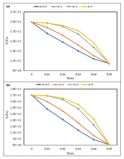
Figure 5.
Variation in Young’s modulus along the radial direction of a porous FG shaft (a) for α = 0.1 (b) for α = 0.2.
6.2. Mode Shapes of Rotor–Bearing System
The first, second and third mode shapes of porous and non-porous FG rotor–bearing systems are plotted in Figure 6a–c for volume fractions of porosity, α = 0.3 and a power law index of 0.5. The dotted line represents the modal displacement curve of a non-porous FG rotor–bearing system, whereas the solid line represents the modal displacement curve of a porous FG rotor–bearing system. The plotted graphs are as expected and can be compared with the mode shapes of rotors with intermediate bearings described in the literature [47]. The natural frequencies corresponding to each mode shape are given in Figure 6a–c.
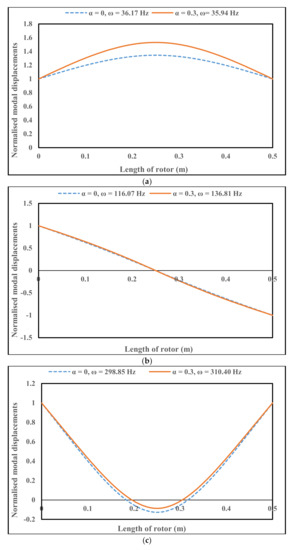
Figure 6.
(a) First mode shape of a porous and non-porous FG rotor–bearing system; power law index (k) = 0.5. (b) Second mode shape of a porous and non-porous FG rotor–bearing system; power law index (k) = 0.5. (c) Third mode shape of a porous and non-porous FG rotor–bearing system; power law index (k) = 0.5.
6.3. The Effect of Porosity on DNFs for Different Power Law Indices (k)
The dimensionless natural frequencies () of the FG rotor–bearing system for different volume fractions of porosity are calculated using , where is the density of stainless steel, is the area of the cross-section of the shaft, is the length of the shaft, is the natural frequency of the shaft in rad/s, is Young’s modulus of stainless steel at room temperature and I is a diametrical moment of inertia. Dimensionless natural frequencies (DNFs) of FG rotor–bearing systems at different volume fractions of porosity are plotted for different power law indices in Figure 7. It has been observed that the DNFs decrease with an increase in the volume fraction of porosity. The DNFs decrease due to a reduction in the material properties such as Young’s modulus and density, while there is an increase in the volume fraction of porosity. Young’s modulus and density for various volume fractions of porosity are tabulated in Table 7. However, the DNF curves of different power law indices converge at α = 0.4 due to a proportional drop in the stiffness and mass of the porous FG shaft for all power law indices. DNFs also decrease with the increase in k. The reason for this is explained in Section 6.4.

Figure 7.
Variation in dimensionless natural frequency (DNF) for different volume fractions of porosity (α).
Table 7.
Young’s modulus and density of ZrO2 and stainless steel (SS) at different α.
6.4. The Effect of Power Law Index on DNFs for Different Volume Fractions of Porosity
Figure 8 shows the variation in DNFs against the power law index for different volume fractions of porosity. It has been observed that the DNFs reach their maximum at k = 0. Since the FG shaft is completely composed of ceramic at k = 0, the ratio of Young’s modulus to the density of a ceramic is high. However, the DNFs of the system decrease with the increase in the power law index. As the power law index increases from zero to five, the composition of the FG shaft alters from an absolute ceramic to an FG shaft that is comprised of a combination of metal and ceramic. The percentage of metal increases in the FG shaft and hence the ratio of Young’s modulus to the density decreases. Eventually, the DNFs of the system are reduced. DNFs with volume fractions that have porosities (α) = 0.1, 0.2 are slightly higher than the DNFs without porosity. This is due to the fact that the reductions in the material properties lead to an increase in the ratio of stiffness and mass as compared to the ratio of the FG shaft without porosity.
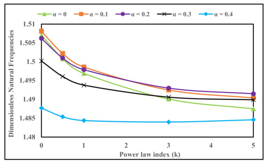
Figure 8.
Variation in DNF for different power law indices (k).
6.5. The Effect of Temperature Gradient on DNFs for Different Values of k and α
The variation in DNFs with the power law index of an FG rotor system with and without porosity for different thermal gradients is plotted in Figure 9a,b. Dimensionless natural frequencies decrease with the increase in the temperature gradient, as expected. This is due to the reduction in material properties, especially Young’s modulus, at higher temperatures. However, the presence of porosities in the FG shaft result in a reduction in Young’s modulus and other material properties, which would lead to the abrupt drop in the DNFs at high temperatures (Toi = To − Ti = 300 or 600). Later, the DNFs slightly increase initially with the power law index (k), but the surge in DNFs eventually becomes barely detectable.
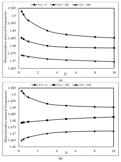
Figure 9.
(a) Variation in DNF of an FG rotor system at different thermal gradients without porosity. (b) Variation in DNFs of a porous FG rotor system for α = 0.2 at different thermal gradients.
6.6. The Effect of Power Law Index, Volume Fraction of Porosity, Thermal Gradient on Whirl Frequencies
The whirl frequencies of the porous FG rotor–bearing system at a shaft speed of 4000 rpm are calculated for different power law indices, volume fractions of porosity and temperature gradients in this work. The results are tabulated in Table 8. As the power law index increases, the whirl frequencies of the FG rotor system decrease. The whirl frequencies decrease with the increase in the temperature gradient as expected due to the reduction in stiffness at higher thermal gradients. The split between 1BW-1FW and 3BW-3FW is minimal compared to the split between 2BW and 2FW. Campbell diagrams for k = 0.5, α = 0, 0.1 and Ω = 4000 rpm, 10,000 rpm at different temperature gradients are shown in Figure 10a–d. The split between 1FW-1BW and 3FW-3BW is barely detectable in the figures.
Table 8.
Whirl frequencies of a porous FG rotor–bearing system for different values of k, α and ∆T.
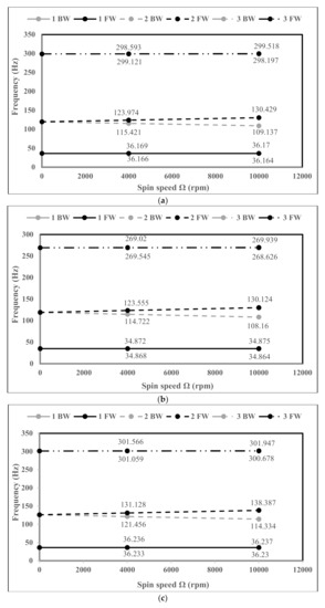
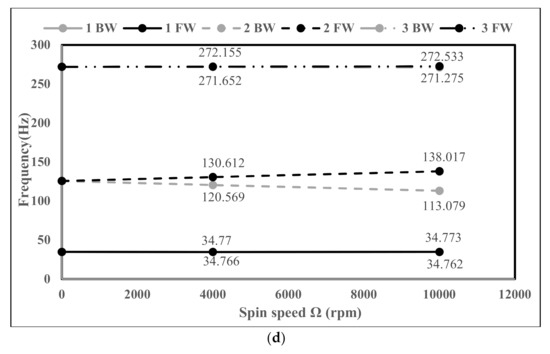
Figure 10.
(a) Campbell diagram of an FG rotor–bearing system for k = 0.5 and ∆T = 0, without porosity. (b) Campbell diagram of a porous FG rotor–bearing system for k = 0.5, α = 0 and ∆T = 600. (c) Campbell diagram of a porous FG rotor–bearing system for k = 0.5, α = 0.1 and ∆T = 0. (d) Campbell diagram of a porous FG rotor–bearing system for k = 0.5, α = 0.1 and ∆T = 600.
7. Conclusions
A dynamic analysis of a porous functionally graded rotor–bearing system has been carried out using the finite element method. The stiffness and mass matrices of a two-noded porous FG shaft are derived in this work. The FG rotor shaft’s inner core is comprised of stainless steel and its outer layer is made of ceramic ZrO2. The effects of porosity, power law index and thermal gradients on the natural and whirl frequencies of an FG rotor system have been analysed and the following conclusions can be drawn from the analysis:
- DNFs decrease with an increase in the volume fraction of porosity (α) due to the reductions in the material properties, which lead to a drop in the stiffness and mass of the porous FG shaft.
- DNFs of the FG shaft with low volume fraction porosity are slightly higher than the DNFs of the FG shaft without porosity. The drop in stiffness and mass escalated the DNFs of the porous FG shaft.
- DNFs of the FG rotor system initially decrease with the increase in k, but later the rate of decrease in DNFs is comparatively low. This is because the percentage of metal is significantly higher at higher power law indices.
- DNFs decrease with an increase in thermal gradients—the reason being that Young’s Modulus reduces at elevated temperatures, which, in turn, reduces the stiffness of the system. However, due to the presence of porosities in the FG shaft, the DNFs drop abruptly at low values of k; however, later, the growth is hardly detectable.
- Whirl frequencies decrease with an increase in the power law index and thermal gradients. The split between the second forward and backward whirl frequencies is significant compared to the split between the first and third whirls.
As the natural and whirl frequencies are affected by various factors of a porous FG rotor system, such as the power law index, volume fraction of porosity and thermal gradients, it is important to analyse the effects of these factors to accurately predict the critical speeds of an FG rotor–bearing system in order to avoid any rotor failures due to resonance. The present analysis provides an important insight into the natural frequency analysis of a porous FG rotor system, which can be used to analyse the dynamic behaviour of a porous FG rotor system at its critical speeds. Further work in this direction could include the modelling of uneven porosity distributions in an FG rotor system in order to investigate their effects on the dynamic properties of the system.
Author Contributions
Conceptualisation, P.S.; methodology and validation, P.S., A.B. and B.O.; writing—original draft preparation, A.B. and B.O.; writing—review and editing, P.S., G.C., R.C. and A.M. All authors have read and agreed to the published version of the manuscript.
Funding
This research received no external funding.
Conflicts of Interest
The authors declare no conflict of interest.
References
- Krishnan, K. Composite Materials: Science and Engineering; Springer Science and Business Media: Berlin, Germany, 2013. [Google Scholar]
- Suresh, S.; Mortensen, A. Fundamentals of Functionally Graded Materials; IOM Communications Ltd.: London, UK, 1998. [Google Scholar]
- Miyamoto, Y.; Kaysser, W.; Rabin, B. Functionally Graded Materials; Springer: New York, NY, USA, 2013. [Google Scholar]
- Koizumi, M. FGM activities in Japan. Compos. Part B Eng. 1997, 28, 1–4. [Google Scholar] [CrossRef]
- Swaminathan, K.; Naveenkumar, D.; Zenkour, A.; Carrera, E. Stress, vibration and buckling analyses of FGM plates—A state-of-the-art review. Compos. Struct. 2015, 120, 10–31. [Google Scholar] [CrossRef]
- Dai, H.; Rao, Y.; Dai, T. A review of recent researches on FGM cylindrical structures under coupled physical interactions, 2000–2015. Compos. Struct. 2016, 152, 199–225. [Google Scholar] [CrossRef]
- Thai, H.; Kim, S. A review of theories for the modeling and analysis of functionally graded plates and shells. Compos. Struct. 2015, 128, 70–86. [Google Scholar] [CrossRef]
- Simsek, M. Static analysis of a functionally graded beam under a uniformly distributed load by Ritz method. Int. J. Eng. Appl. Sci. 2009, 1, 1–11. [Google Scholar]
- Liu, N.; Ren, X.; Lua, J. An isogeometric continuum shell element for modeling the nonlinear response of functionally graded material structures. Compos. Struct. 2020, 237, 111893. [Google Scholar] [CrossRef]
- Liu, N.; Jeffers, A. Isogeometric analysis of laminated composite and functionally graded sandwich plates based on a layerwise displacement theory. Compos. Struct. 2017, 176, 143–153. [Google Scholar] [CrossRef]
- Simsek, M. Fundamental frequency analysis of functionally graded beams by using different higher-order beam theories. Nucl. Eng. Des. 2010, 240, 697–705. [Google Scholar] [CrossRef]
- Aydogdu, M.; Taskin, V. Free vibration analysis of functionally graded beams with simply supported edges. Mater. Des. 2007, 28, 1651–1656. [Google Scholar] [CrossRef]
- Pydah, A.; Sabale, A. Static analysis of bi-directional functionally graded curved beams. Compos. Struct. 2017, 160, 867–876. [Google Scholar] [CrossRef]
- Pradhan, K.; Chakraverty, S. Free vibration of Euler and Timoshenko functionally graded beams by Rayleigh–Ritz method. Compos. Part B Eng. 2013, 51, 175–184. [Google Scholar] [CrossRef]
- Li, W.; Gao, W.; Chen, S. A material-based higher-order shear beam model for accurate analyses of FG beams with arbitrary material distribution. Compos. Struct. 2020, 245, 112253. [Google Scholar] [CrossRef]
- Dimentberg, F. Flexural Vibrations of Rotating Shafts; Butterworths: London, UK, 1961. [Google Scholar]
- Ruhl, R.; Booker, J. A Finite Element Model for Distributed Parameter Turborotor Systems. J. Eng. Ind. 1972, 94, 126–132. [Google Scholar] [CrossRef]
- Nelson, H.; McVaugh, J. The Dynamics of Rotor-Bearing Systems Using Finite Elements. J. Eng. Ind. 1976, 98, 593–600. [Google Scholar] [CrossRef]
- Nelson, H. A Finite Rotating Shaft Element Using Timoshenko Beam Theory. J. Mech. Des. 1980, 102, 793–803. [Google Scholar] [CrossRef]
- Gayen, D.; Roy, T. Finite element based vibration analysis of functionally graded spinning shaft system. Proc. Inst. Mech. Eng. Part C J. Mech. Eng. Sci. 2014, 228, 3306–3321. [Google Scholar] [CrossRef]
- Bose, A.; Sathujoda, P. Natural frequency analysis of a functionally graded rotor system using three-dimensional finite element method. Vibroeng. Procedia 2019, 29, 70–75. [Google Scholar] [CrossRef]
- Mahi, A.; Bedia, E.A.; Tounsi, A.; Mechab, I. An analytical method for temperature-dependent free vibration analysis of functionally graded beams with general boundary conditions. Compos. Struct. 2010, 92, 1877–1887. [Google Scholar] [CrossRef]
- Fallah, A.; Aghdam, M. Thermo-mechanical buckling and nonlinear free vibration analysis of functionally graded beams on nonlinear elastic foundation. Compos. Part B Eng. 2012, 43, 1523–1530. [Google Scholar] [CrossRef]
- Zhang, D. Thermal post-buckling and nonlinear vibration analysis of FGM beams based on physical neutral surface and high order shear deformation theory. Meccanica 2013, 49, 283–293. [Google Scholar] [CrossRef]
- Kiani, Y.; Eslami, M. Thermal buckling analysis of functionally graded material beams. Int. J. Mech. Mater. Des. 2010, 6, 229–238. [Google Scholar] [CrossRef]
- Bose, A.; Sathujoda, P. Effect of Thermal Gradient on Vibration Characteristics of a Functionally Graded Shaft System. Math. Model. Eng. Probl. 2020, 7, 212–222. [Google Scholar] [CrossRef]
- Gayen, D.; Chakraborty, D.; Tiwari, R. Free Vibration Analysis of Functionally Graded Shaft System with a Surface Crack. J. Vib. Eng. Technol. 2018, 6, 483–494. [Google Scholar] [CrossRef]
- Gayen, D.; Chakraborty, D.; Tiwari, R. Whirl frequencies and critical speeds of a rotor-bearing system with a cracked functionally graded shaft—Finite element analysis. Eur. J. Mech. Solids 2017, 61, 47–58. [Google Scholar] [CrossRef]
- Zhu, J.; Lai, Z.; Yin, Z.; Jeon, J.; Lee, S. Fabrication of ZrO2–NiCr functionally graded material by powder metallurgy. Mater. Chem. Phys. 2001, 68, 130–135. [Google Scholar] [CrossRef]
- Wattanasakulpong, N.; Prusty, B.G.; Kelly, D.; Hoffman, M. Free vibration analysis of layered functionally graded beams with experimental validation. Mater. Des. (1980–2015) 2012, 36, 182–190. [Google Scholar] [CrossRef]
- Akbas, S. Forced vibration analysis of functionally graded porous deep beams. Compos. Struct. 2018, 186, 293–302. [Google Scholar] [CrossRef]
- Ebrahimi, F.; Jafari, A. A Higher-Order Thermomechanical Vibration Analysis of Temperature-Dependent FGM Beams with Porosities. J. Eng. 2016, 2016, 1–20. [Google Scholar] [CrossRef]
- Ebrahimi, F.; Mokhtari, M. Transverse vibration analysis of rotating porous beam with functionally graded microstructure using the differential transform method. J. Braz. Soc. Mech. Sci. Eng. 2015, 37, 1435–1444. [Google Scholar] [CrossRef]
- Ait Atmane, H.; Tounsi, A.; Bernard, F. Effect of thickness stretching and porosity on mechanical response of a functionally graded beams resting on elastic foundations. Int. J. Mech. Mater. Des. 2015, 13, 71–84. [Google Scholar] [CrossRef]
- Wattanasakulpong, N.; Chaikittiratana, A. Flexural vibration of imperfect functionally graded beams based on Timoshenko beam theory: Chebyshev collocation method. Meccanica 2015, 50, 1331–1342. [Google Scholar] [CrossRef]
- Wattanasakulpong, N.; Ungbhakorn, V. Linear and nonlinear vibration analysis of elastically restrained ends FGM beams with porosities. Aerosp. Sci. Technol. 2014, 32, 111–120. [Google Scholar] [CrossRef]
- Sathujoda, P.; Obalareddy, B.; Batchu, A.; Canale, G.; Maligno, A.; Citarella, R. Effect of Corrosion on the Natural and Whirl Frequencies of a Functionally Graded Rotor-Bearing System Subjected to Thermal Gradients. Materials 2020, 13, 4546. [Google Scholar] [CrossRef] [PubMed]
- Bose, A.; Sathujoda, P. Natural Frequency Analysis of a Porous Functionally Graded Shaft System. Int. J. Aerosp. Mech. Eng. 2020, 14, 123–131. [Google Scholar]
- Aboudi, J.; Pindera, M.; Arnold, S. Higher-order theory for functionally graded materials. Compos. Part B Eng. 1999, 30, 777–832. [Google Scholar] [CrossRef]
- Shen, H. Functionally Graded Materials; CRC Press: Boca Raton, FL, USA, 2009. [Google Scholar]
- Touloukian, Y. Thermophysical Properties of High Temperature Solid Materials; Macmillan: New York, NY, USA, 1967. [Google Scholar]
- Jagtap, K.; Lal, A.; Singh, B. Uncertainty quantification in non-linear dynamic response of functionally graded materials plate. Mech. Adv. Mater. Struct. 2017, 25, 1081–1100. [Google Scholar] [CrossRef]
- Fu, C.; Xu, Y.; Yang, Y.; Lu, K.; Gu, F.; Ball, A. Response analysis of an accelerating unbalanced rotating system with both random and interval variables. J. Sound Vib. 2020, 466, 115047. [Google Scholar] [CrossRef]
- Reddy, J.; Chin, C. Thermomechanical analysis of functionally graded cylinders and plates. J. Therm. Stress. 1998, 21, 593–626. [Google Scholar] [CrossRef]
- Lanhe, W. Thermal buckling of a simply supported moderately thick rectangular FGM plate. Compos. Struct. 2004, 64, 211–218. [Google Scholar] [CrossRef]
- Friswell, M. Dynamics of Rotating Machines; Cambridge University Press: Cambridge, UK, 2010. [Google Scholar]
- Swanson, E.; Powell, C.D.; Weissman, S. A practical review of rotating machinery critical speeds and modes. Sound Vib. 2005, 39, 10–17. [Google Scholar]


Publisher’s Note: MDPI stays neutral with regard to jurisdictional claims in published maps and institutional affiliations. |
© 2020 by the authors. Licensee MDPI, Basel, Switzerland. This article is an open access article distributed under the terms and conditions of the Creative Commons Attribution (CC BY) license (http://creativecommons.org/licenses/by/4.0/).