1. Introduction
Torque sensors are devices used to measure axial torque in rotating systems such as motors, engines, robot joints, and so on. A torque applied to a cylinder can be calculated by measuring the torsional deformation of the cylinder surface, just like measuring the applied axial force using a strain gauge on a component. The performance of the torque sensors can be largely evaluated by measurement range and sensitivity, but it is difficult for them to be compatible together. Increasing the sensor sensitivity reduces the measurement range, whereas a sensor with a wider measurement range must be less sensitive. When using conventional torque sensors, an appropriate compromise between the required measurement range and sensitivity suitable for the purpose is essential at the purchasing stage of the sensor.
Recently, force/torque sensors are being used in a variety of fields to improve systems with high performance control of robots, beyond simple measurement [
1]. Kim et al. developed a multi-axial force/torque sensor that can measure six-axial force and torque for robotic application [
2], and Estevez et al., also developed a 6-DOF sensor for micro manipulation [
3]. Some studies have developed methods to improve the accuracy of torque measurements [
4,
5,
6], while others have developed torque sensors that can have wide measurement range [
7,
8]. Meanwhile, some torque sensors have been developed for biomedical purposes [
9,
10]. Minimally invasive surgical robots to which force/torque sensors are applied for safe operation are still being studied actively [
11,
12]. Recently, research has been conducted by Guo et al., to apply a force/torque sensor to a system that enables catheterization at a distance [
13]. Song et al., tried to secure the safety of minimally invasive robotic surgery (MIRS) by using an optical fiber Bragg grating (FBG) force sensor [
14].
For these various purposes of force and torque measurement, different types of force/torque sensors have been developed. The most representative strain gauge type torque sensors are widely used due to their high accuracy. Force/torque measurement using non-contact displacement sensors such as optical, capacitive and inductive sensors requires a large displacement to obtain high sensitivity, which inevitably lowers the stiffness of the sensor. The FBG sensor has the advantage of accurate measurement of strain on an object like the traditional electronic strain gauge, and it is also sterilizable with a small size. However, its application is limited due to the complexity and high cost of the sensor system. Therefore, so far, electronic strain gauge-based force/torque sensors or simple strain gauge load cells are mainly used in robotic applications with high measurement accuracy and relatively low price [
15].
Torque sensors for robot joints must simultaneously satisfy torsional stiffness and sensitivity in a compact size. Khan et al. developed a square-cut torque sensor (SCTS) by modifying a conventional planar hub-sprocket type torque sensor, and they applied it to a hydraulic quadruped robot [
16,
17]. Similarly, Ubeda et al. have developed a torque sensor that can be manufactured inexpensively using a computerized numerical control (CNC) milling machine [
18]. Along with these, torque sensors with two stacked hollow disks with wing pairs are also commonly used. In particular, Aghili et al. proposed a hexaform torque sensor composed of an increased number of wing pairs to satisfy both stiffness and sensitivity [
19]. It is also possible to measure multi-axial force/torque by applying a similar structure such as the Stewart platform [
20,
21]. However, the high-priced multi-axial sensors are not always better than single axis sensors, because excessive measurable dimensions that are not suitable for a given situation can cause inaccurate output force/torque or inaccurate motion due to low sensor stiffness.
Torque sensors are required in a variety of industries, but in many cases, these industries cannot afford expensive products. Unnecessarily high specifications and various functions of the sensors definitely result in high cost, making it difficult to satisfy industries that require simple and rough torque measurements only. Complex usage and limited measurement capacity also make it difficult to use them with limited time and cost. Some studies have suggested methods for measuring torque at relatively low cost [
22,
23,
24]. Especially for medical purposes, various studies on disposable torque sensors that can be discarded are being actively pursued to avoid the risk of infection [
25,
26]. Unlike the medical systems, which are developed long-term, manufacturing fields are directly related to the practical use of the torque sensors. Qin et al. developed a high performance torque sensor that can be applied to a milling system using microelectromechanical systems (MEMS) strain gages [
27]. For a similar purpose, Wu et al. are developing a multi-axial sensor that can be applied to a drilling bit [
28]. However, in most of these torque measurements it is impossible to adjust the measurement range and sensitivity of the sensor, since the measuring sensor is tightly assembled to a specific part of a system.
As can be seen from the history of the dynamometer, measuring the reaction torque using lever arms and load cells is one of the most typical torque measurement methods [
29]. However, the ratio of the measured force to the converted torque is still not adjustable due to the fixed length of the lever arm. In general, the lever arm length acts as a moment arm that generates torque, so that the length and the accuracy can be easily changed by adjusting the moment arm length. Nevertheless, the physical limitation of the moment arm limits the measurement range and sensitivity. Lever arms cannot be infinitely long due to problems of weight and deformation. On the contrary, it is also difficult to make its length very short for the connection part of the load cell.
In this study, we propose a cost-effective torque sensor that can adjust the measurement range and sensitivity by changing the length of a moment arm attached to the load cell in accordance with a measurement situation. First, a vertical model to install a load cell vertically with a simple and intuitive way is presented. Then, it is extended to a generalized oblique model in which the arrangement of the load cell and lever/base arms is tilted to further adjust the length of the moment arm. By using the oblique model, an extremely short moment arm length can be achieved, which can guarantee very high sensitivity for torque measurement. In addition, the proposed torque sensor is combined with a dc motor, so that it can continuously measure the applied torque while changing the angle of the joint or other object. In order to verify the performance of the proposed torque sensor, a sinusoidal output torque is measured by rotating weights on a weight arm. Experiments are carried out by changing the applied torque and the moment arm length of the installed load cell. Furthermore, the sensor is applied to evaluate the performance of a commercial product to show a practical application example. Finally, discussion and conclusion regarding this study are presented in the last section.
2. Torque Sensor Design
The torque sensor developed in this study basically has a structure similar to a general dynamometer using a lever arm. Force measured on the load cell assembled with the lever arm is multiplied by the length of the moment arm to compute the applied torque. In order to measure the torque in both directions with cost effectiveness, a general S-type low-capacity load cell can be utilized. Furthermore, the assembly position of the lever arm to which the load cell is connected must be changeable so that the measurement range and sensitivity of the torque sensor can be adjusted. Additionally, the proposed sensor can be combined with a dc motor in order to continuously measure the torque required to rotate an object. Therefore, the design of the torque sensor is proposed by dividing this section into three parts as follows. First, a vertical model in which the load cell is vertically coupled to the lever arm and the base arm is described. The angular error is estimated by considering the deformation of the two arms due to the applied torque. Next, we propose an oblique model that generalizes the vertical model. The oblique model enables extremely sensitive torque sensors to be implemented. The last part shows a prototype of the actual sensor assembly that was designed and manufactured.
2.1. Vertical Model
Torque is defined as the product of the force and the moment arm length. Utilizing this simple definition, it is possible to measure torque without commercial torque sensor.
Figure 1 shows a schematic of the proposed torque sensor using a load cell with simple other components. The lever arm and the base arm have a number of assembly holes to fix the ends of the load cell on them. In order to measure high torque with the limited capacity of the load cell, long lever and base arms are essential. However, it is physically impossible to make them infinitely long for high inertia and large bending deformation. Especially, if the arms are not rigid enough, the assembled sensor can show considerable hysteresis. Therefore, it is required to predict the deformation of the two arms to minimize the sensor inaccuracy.
If the lever arm and the base arm have same cross-sectional dimensions: width
b and height
h, their area moment of inertia are expressed as
IL =
bLhL3/12 and
IB =
bBhB3/12, where the subscripts
L and
B represent
lever and
base, respectively. Furthermore, if a counter-clockwise torque is applied to the motor shaft, the two arms will deform for the vertical reaction force
F applied by the load cell as shown in
Figure 2. It is assumed that the two arms are nearly parallel to each other and the load cell is assembled vertically for the simple vertical model. Then, the Euler–Bernoulli beam theory yields the deflections of the arms on the load cell position as follows:
where
EL and
EB denote Young’s modulus of the lever and the base arms, and they have the same length of
L. In addition, the longitudinal deformation of the load cell
δLC by the applied normal force
F can be expressed as follows by using the stiffness of the load cell
kLC:
δLC =
F/
kLC or
δLC =
τ/
LkLC. If their deformation is small, the resultant angular deflection or the error of the measured angle will be
Here, if the two arms have same cross-sectional dimension and Young’s modulus:
EB =
EL and
IB =
IL, the angle error or torsional deformation can be simplified as follows:
As a result, torsional stiffness of this torque sensor
KT =
τ/
θT can be expressed as follows:
For example, if the linear stiffness of the load cell is kLC = 0.5 × 10⁶ N/m with the 200 mm long two arms of bL = 5, hL = 20 (mm) and EL = 69 GPa, the maximum payload capacity of the load cell Fmax = 50 N or maximum applied torque τmax = 10 N·m yields: δL + δB + δLC = 1.26 mm and θT = 0.36°. This angular deflection will be negligible for most applications, and moreover it can be reduced by design modification. It will also work to substitute the arms material with another of higher elasticity.
The torsional stiffness of this sensor is determined by two terms, as can be seen in Equation (4): bending of the two arms and axial deformation of the load cell. Depending on the length
L, the governing term that affects the torsional deformation and stiffness of the sensor changes.
Figure 3 shows the changes in torsional deformation and stiffness by changing the length
L in the example just above. In this example, when
L = 88 mm, the influence of the arms bending and axial deformation of the load cell on the torsional deformation becomes the same. In addition,
L = 70 mm leads to the minimum torsional deformation
θT = 2.1 × 10
−3 degree, and
L = 111 mm results in the maximum torsional stiffness
KT = 2066 Nm.
If the arm length L is short, or if the bending stiffness of the base and lever arms is sufficiently large, to neglect the bending deflection the two arms, Equations (4) and (5) can be simplified as: θT ≈ τ/L2kLC and KT ≈ L2kLC. Therefore, in that case, the torsional stiffness of the sensor will be proportional to the square of the arms length L. On the contrary, if the length L is long enough, the arms bending has a major effect on the torsional deformation and stiffness. Unfortunately, the long arms also have a bad effect on the bandwidth, one of the important specifications of this sensor. The longer the length L, the larger the mass moment of inertia of the rotary parts and the torsional stiffness decreases. Therefore, a long L will greatly reduce the natural frequency of this torque sensor, resulting in a narrow bandwidth.
2.2. Generalized Obique Model
Generalizing the vertical model described previously, the load cell can be installed slantly on purpose as shown in
Figure 4. In this oblique model, if the load cell can rotate freely about the joints connecting with the base and lever arms, only pure axial force is applied to the load cell. Here,
LL and
LB mean the lengths of the lever arm and the base arm, respectively, while
dL and
dB represent the vertical distances from the motor shaft to the arms.
LLC means the length of load cell between the upper and lower connecting points on the lever and base arms. With this information, the following moment arm length of the exerted force on the lever arm by the load cell,
dLC, can be provided by applying Heron’s formula to the area of the triangle
OBC:
Here, the length
hL and
hB are the hypotenuse of the two right angle triangles
OCD and
OAB, respectively, and they can be substituted with the followings:
If the lever arm line
CD is parallel with the base arm line
AB, Equation (6) can be expressed as
or
without
LLC. This expression must be more desirable, because
LLC can be adjusted to make the lever arm parallel to the base arm in practical use. Again, if the motor axis is on the lever arm line
CD (
dL = 0), the moment arm is simplified as follows.
With this method utilizing the oblique load cell installation, an extremely short moment arm can be accomplished.
Figure 5 shows an example to obtain the short moment arm using this oblique model. It is evident that a small
dLC can be achieved by small
dB and
LL with a fixed length of
LB. As a result, it is possible to make
dLC = 6.608 mm when
LB = 200,
dB = 20 and
LL = 50 mm, even with the parallel
AB and
CD: in this case,
LLC = 151.327 mm. They are very practical values for use, and
dB cannot be zero in a general way for physical limitation. Furthermore, in order to achieve shorter moment arm, it is needed to return to Equations (6)–(8). Utilizing Equation (6), the following condition can be obtained to make
dLC = 0:
Among the four possible solution sets for this relation, the most intuitive one with regard to
Figure 4 is following:
hB =
LLC +
hL. It means that the upper connecting point of the load cell on the lever arm
C needs to be close to the straight line between the motor axis and the lower connecting point of the load cell on the base arm
OB.
If the lever arm line
CD is below the motor axis
O, or
dL has negative length, the moment arm
dLC can be much shorter, as can be seen from Equations (9) and (10). Although the line
CD is above the axis
O, a negative value of
LL can similarly lead to a very short moment arm. Even when the lengths of the all components are fixed, it is still possible to reduce the moment arm
dLC by adjusting the load cell length
LLC. For example, a condition of
LL = 50,
dL = 0,
LB = 200 and
dB = 20 mm with
LLC = 151.005 mm can yield a short moment arm
dLC = 1 mm, although the two lines
AB and
CD are not parallel. Therefore, any desirable length of the moment arm can be obtained by adjusting other components length; especially adjusting the load cell length
LLC is helpful for fine moment arm. From Equation (6), the unknown
LLC for the fixed other values is expressed as follows:
for the case of the parallel
AB and
CD.
The problem here is that a small
dLC is hypersensitive to
LLC. It means that a slight adjustment error of
LLC causes a considerable difference in
dLC, which will result in measurement inaccuracy.
Figure 6 demonstrates how dependent
dLC is on
LLC and the curve starts at
LLC = 150.9975 mm. On the starting point the curve has an infinite slope, which can be derived from Equation (6) as follows:
From this curve, it is implied that an excessively short moment arm is difficult to guarantee its length, because it is susceptible to the deformation of the components or to the clearance of the component connections. Moreover, in this oblique model, not only pure bending moment, but also axial load is applied together to the lever and base arms, consequently reducing the sensor stiffness. In order to prevent such undesirable distortion of the moment arm length for the oblique model, it is essential to design the components to minimize deformation and clearance. On the other hand, the vertical model described in the previous section is relatively far less affected by the components deformation and the connection clearance.
2.3. Design and Prototype
The proposed sensor is designed in detail as shown in
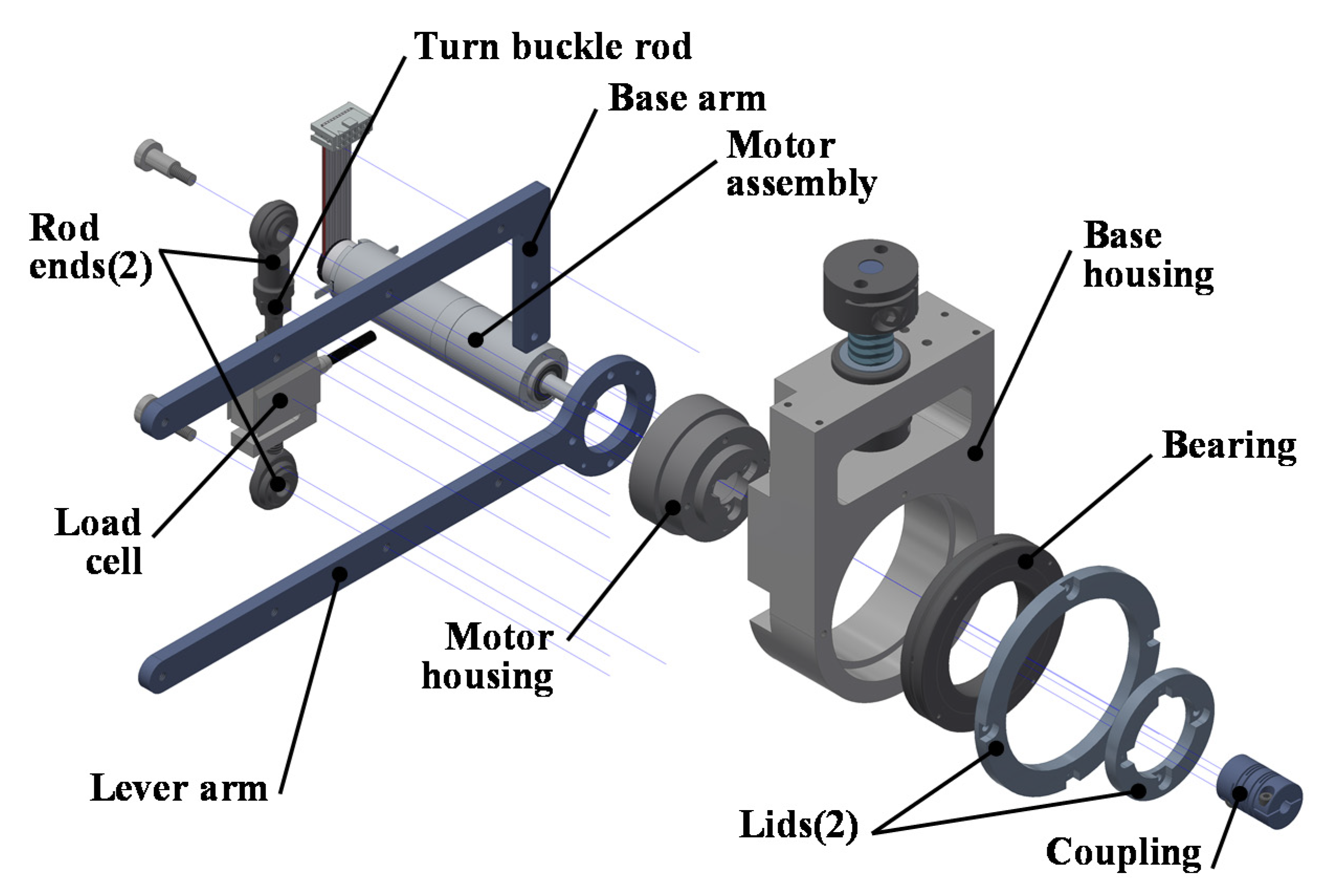
Figure 7, so that the two arms are parallel. Based on the assembly position of the load cell, the length of the lever and base arms can be selected from 50, 100, 150 and 200 mm. The load cell is connected to the two arms via rod end bearings, one of which utilizes a turn buckle rod to adjust the length of the load cell. The base arm is fixed to the base housing, while the lever arm combined with the motor assembly and the motor housing can rotate with respect to the base housing. The crossed roller bearing (CRB) reduces friction between the two housing parts, allowing for smooth rotation. Among the two lids, the larger one fixes the outer ring of the CRB to the base housing, while the smaller one fixes the inner ring of the CRB to the motor housing. The distal coupling connects the motor shaft to a test object shaft. The following components are utilized for the sensor configuration: (Bongshin) DBCM-5 load cell, (Misumi) PHSOSN6 and PHSSLN6 rod ends, SLBRS6-30 turnbuckle rod, (THK) RB4010UUC0 CRB, (Maxon motor) DCX22L motor, GPX22 243:1 planetary gearhead, and ENX16 EASY 1024IMP encoder sensor.
The previously designed torque sensor is assembled with a base frame as shown in
Figure 8. A weight is located on a long weight arm connected to the motor shaft. The weight arm is symmetrical about the rotating axis for counter-balancing of the arm itself, therefore only the distal weight applies torque to the torque sensor. As shown on the right side of the figure, it is possible to acquire various moment arm length by means of the multiple holes to assemble the rod ends of the load cell on the base and lever arms; the
Figure 8c utilizes another base arm link to minimize the vertical distance from the motor shaft to the base arm (
dB = 20 mm). Since the number of holes on the two links is limited, a tilted load cell assembly as mentioned in the oblique model is required for a very short moment arm length of less than 50 mm. The shortest moment arm
dLC = 6.608 mm is obtained by
LL = 50,
dL = 0,
LB = 200 and
dB = 20 mm, even though the lever arm is parallel with the base arm. If the utilized motor is not limited and other parts are not replaced, the maximum measurable torque of this torque sensor is 9.81 Nm.
5. Discussion and Conclusions
Using the suggested torque sensor, the measurement range is determined by the length of the moment arm in which the load cell is installed. Accordingly, the proposed torque sensor has the advantage of easy adjustment of the measurement range and sensitivity by changing the load cell position without further manufacturing or changing other components. However, what is clear is that, thanks to the structure of the adjustable moment arm, it can be modified immediately to have the required sensitivity or measurement range for users. For example, if the length of the moment arm is reduced from 1000 mm to 10 mm, the measurement range of this sensor decreases to 1/100, but the sensitivity increases by 100 times. Additionally, this is not the only advantage that the proposed torque sensor has due to its structural features. This sensor has the property of resisting other-axes torque/force structurally by applying the CRB. Additionally, the ball end bearings at both ends of the load cell transmit only pure axial force to the load cell, thereby fundamentally blocking the influence of other torque/force on the torque measurement. Resultantly, it is possible to accurately measure only the torque in the direction of interest.
However, in return for gaining this huge advantage of adjustment, this sensor has distinct limitations. The most important specifications in the proposed torque sensor are directly affected by the arms length L. By the relationship of F = τ/L, sensitivity of this sensor will be inversely proportional to L. Consequently, in order to secure high sensitivity of the proposed sensor, a short L is required. The output resolution will decrease in inverse proportion to L, like the sensitivity. Furthermore, the measurement range of this torque sensor is also directly affected by length L. If the applied load cell is not changed, the measurement range increases in proportion to L. Additionally, the long L lowers the physical natural frequency of the torque sensor with the weight of the load cell far from the center of rotation, which inevitably narrows its bandwidth. Excluding the motor part from the sensor prototype, the natural frequency of this sensor can be predicted by using the weight and stiffness of the load cell, lever arm and base arm. For example, it is calculated to have the natural frequencies of about 147 Hz and 116 Hz, respectively, when the load cell is integrated at a distance of 50mm and 200mm. Therefore, it will be reasonable to estimate the measurement bandwidth of this torque sensor prototype used in the experiment at the level of about 100 Hz.
With a small-capacity load cell, it is possible to change a variety of measurement ranges, but it is difficult to simultaneously satisfy the specifications for high impact applications, such as high sensitivity, high bandwidth and wide measurement range. For the high impact applications, therefore, a huge-capacity load cell and a short moment arm with high bending stiffness will be essential. Consequently, in order to meet the required level of the sensor specifications, it is very important to properly select the arms length L together with the specifications of the utilized load cell itself.
Despite the structural advantages of this torque sensor, the advantages were not conspicuously revealed in the previous experiments. In particular, it was difficult to confirm the change in sensitivity by changing the moment arm in the result of the second fundamental experiment. However, without a reference sensor, the new and simple method of evaluating the performance of the torque sensor using the weight rotation showed satisfactory results. It is also necessary to discuss the experimental method of measuring the performance of the torque sensor, which is not desirable but notable, used in this study. As shown in the two experiments of
Section 3, the measured torque errors were not negligible. The major cause of this problem was the backlash of the gear train inside the driving motor. It is reasonable to regard this phenomenon as a result of the actuator performance rather than the torque sensor.
Figure 13 is the simulation result to show the inaccuracy of the measured torque when an input torque is applied to the torque sensor, by rotating a distal weight in one direction using an actuator with a huge reducer backlash. When a maximum input torque of 117.2 mNm is applied as in Experiment 2, a 10° sampling interval and 40° actuator backlash leads to a resultant torque RMSE of 27.88 mNm, exaggeratedly. More practically, in the case of 0.01° sampling interval and 1.9° actuator backlash, the resultant torque RMSE 1.3753 mNm is substantially similar to the first RMSE measured in the experiment (1.2454, 1.2226 and 1.2444 mNm). Therefore, it can be said that the error in
Section 3 was mostly caused by the actuator backlash. As evidence, it was confirmed that when the rotation angle range was limited to 1–179°, the measurement error dramatically decreased to less than 30% of the previous value. In conclusion, it is not desirable to generate the sine-type torque using an actuator using a gear reducer as in this study, and it is recommended to replace the gear, for example with a harmonic drive reducer that can ignore the backlash of the reducer. Alternatively, it is also desirable to use this motor-equipped torque sensor within a limited range where the direction of torque does not change.
Another limitation of this study is that the dynamic characteristics of the proposed torque sensor were not experimentally quantified. However, the natural frequency of the torque sensor was calculated through the kinematic calculation, and the result made it possible to approximate the bandwidth of this sensor. As described previously, the purpose of this study is to propose a new torque sensor structure, and to predict and evaluate its basic performance. Therefore, additional measurements of the dynamic properties and practical application methods of this sensor are left as future works. In addition, it was not clearly revealed through this study that the measurement sensitivity can be adjusted by changing the length of the moment arm. If the equipped motor is removed and only the performance of the torque sensor is measured, the adjustability of the sensitivity will inevitably become remarkable, but it is regrettable that this characteristic has not been completely proven due to the limitations of the backlash and coarse motion control of the actuator with the current experimental methods.
Nonetheless, there are some ways to improve the performance of this torque sensor through component replacement and design modifications. First, if the currently used planetary gear head is replaced with a harmonic drive, the angle of the rotary shaft becomes accurate, and the hysteresis of the measurement can be dramatically reduced. Although torsional wind-up phenomenon can cause inaccurate torque measurements, it will generally be better to secure positional accuracy by deceleration by harmonic drive rather than gear, unless the measured torque is at an extremely low level. Furthermore, replacing the rod ends with other components of less friction and less clearance will also work. A reinforced design to minimize strain on the lever and base arms is also a good way to improve the measurement accuracy for high torque. Lastly, utilizing another load cell with high performance will understandably improve the measurement accuracy.
One of the typical advantages of the proposed torque sensor is its wide applicability and its relatively high cost effectiveness, which would be very welcome in many industries. The way to maximize this inexpensive advantage is quite the opposite of the performance improvements mentioned above. First, the CRB used to enable fine rotation of the motor can be replaced with a less expensive component. Common ball bearings or plain bearings can be used as alternatives. Furthermore, replacing the bearing with a compliant mechanism that allows small rotation will greatly simplify the sensor structure. Next, the rod end bearings applied to the connection of the load cell and the lever/base arms can be also removed to be joined integrally. Users can also consider applying a strain gauge on the integral component instead of the load cell; this method may unduly reduce the accuracy of the torque measurement, so it would be desirable to avoid this replacement. Lastly, it is also considerable to remove the motor itself to fix the rotary motor armature and shaft on the lever arm. The motor is not an essential component for economic application, and it can cause a limit to the measurement range. A fixed shaft connecting the base arm and the distal coupling can eliminate the motor housing as well. Currently, excluding the motor assembly, the manufacturing cost of the torque sensor prototype is about $670 ($300 for the load cell; $220 for the commercial components such as the rod end bearings and the CRB; $150 for the machined components such as the levers, the housings and the lids). Therefore, it is currently difficult to claim the cost-effectiveness of this sensor with this cost. However, the current cost could be significantly reduced by modifying the design and changing the utilized commercial components. Assuming that a user can apply an existing load cell, the cost of configuring this torque sensor is expected to be reduced to less than $100. Compared to existing commercial torque sensors, this price is unusually cheap. Even if the load cell is included in the price of the torque sensor, considering its adjustability of measurement range and sensitivity, it will have sufficient competitiveness.
Other application methods of the single-axis torque sensor proposed in this study can be considered together. First of all, this torque sensor is limited in miniaturization due to its long arms, so it will not be easy to build this sensor itself into the rotary joints of a robot system. However, this torque sensor could be embedded in the robots during the development stage of prototypes without severe space constraints, or it can be effectively used as an external measuring device for evaluating the performance of developed robots without built-in joint torque sensors [
32]. Next, by adopting the structure of this torque sensor, it will be possible to extend to multi-axial measurement. For example, a six-axis force/torque sensor in the form of a hexagonal column with six legs that are not parallel to each other, similar to a Stewart platform, would be configurable. A wide measurement range can be obtained by using wide top and bottom plates with long arms, while high sensitivity can be obtained by using the aforementioned oblique model or a near-singular configuration [
33]. In addition, if combined with a position sensor that can monitor the exact position of the combined load cell in real time, the measurement errors caused by deformation for high torque can be offset. In particular, in the oblique state of the extremely short moment arm, the rotational stiffness of this sensor decreases, and the influence of the assembly clearance increases. Therefore, it is expected that the presence of additional position sensors can greatly improve the measurement accuracy.
The sensor proposed in this study can be applied to various torque measurements. As in the example shown above, it is possible to maximize the balancing ability by measuring the torque applied to the joints in the balanced-arms. It is a great advantage to be able to adjust the measuring range and accuracy of the sensor simply by repositioning load cell only, without replacing any components. Furthermore, due to its simple structure and high cost effectiveness, it is likely to be widely used in various industries.


