1. Introduction
The lubrication of mechanical components plays a key role in ensuring their reliable functioning in terms of wear reduction, efficiency improvement, and in maintaining an appropriate operating temperature both by reducing the heat generation and by promoting its dissipation [
1]. However, even if the lubrication allows the reduction of power losses due to friction, the interaction between the lubricant and the moving structures implies additional power losses due to viscous and inertial effects [
2]. The prediction of these power losses has been studied in the past through experimental tests. Based on these measurements, several empirical/analytical models have been proposed [
3]. However, those models are unreliable for predicting power losses when the geometries, the speeds or the lubricant properties differ from those observed/selected during the experimental tests [
3]. In other words, their ranges of applicability are only those on which they have been calibrated. Moreover, the analytical models do not provide any indications on the lubricant distribution, a fundamental aspect to ensure/confirm the proper lubrication for all the critical components [
3].
Therefore, nowadays, with the aim of studying lubricant behavior in machine components and predicting the related power losses, CFD analyses can be exploited. Indeed, in addition to the possibility to simulate different lubricant properties, CFD simulations can be applied to any geometrical configuration and operating condition [
4]. This allows overcoming the limitations of the empirical and analytical models even if it requires higher computational efforts. Moreover, the possibility to get information in each point of the computational domain (i.e., the studied volume in which fluids can be present) helps to understand the physical phenomena behind the lubrication and its effectiveness.
In order to carry out CFD analysis simulating the lubricant behavior in machine components, it is necessary to deal with many challenges that affect both the effectiveness and the efficiency of the simulations. Indeed, since the main lubricated components are gearboxes, pumps and bearings, it is easy to understand how different systems require the study of different physical phenomena, e.g., windage (single-phase), churning (multi-phase), cavitation, etc., by handling topological changes of the computational domain and/or defining specific boundary conditions.
The CFD approaches can be classified into mesh-based or meshless (mesh-free) approaches [
5]. Some hybrid methods can be found in the literature, e.g., fast fluid dynamics [
6] and the particle in cell method [
7]. However, these hybrid methods are not used in the study of lubrication of mechanical systems. Mesh-based approaches can accurately describe the phenomena at any physical scale. However, any topological modification of the computational domain and/or the motion of the boundaries affect their applicability [
3,
5]. On the other hand, the meshless approaches discretizes the fluid instead of the spatial domain [
8]. Indeed, these approaches divide the fluid (i.e., the lubricant) into a set of discrete elements also called particles [
8,
9]. The evaluation of a field variable that can be the viscosity, the density etc. can be calculated by summing the relevant properties of all the particles. Although the meshless approaches can be easily applied to simulate the lubricant behavior in complex systems (since the mesh-handling issues are not present), the accuracy of the results in terms of power losses have been proved to be inadequate for most of the mechanical engineering applications [
3].
Therefore, on one hand, mesh-based CFD approaches can simulate multiple physical phenomena accurately but their applicability is limited by challenge of discretizing the computational domain at each time step. On the other hand, meshless CFD approaches can be easily applied to computational domains that vary in time and space, but the physical phenomena that can be simulated are limited and therefore the reliability of some types of results is questionable.
The purpose of this paper is to review the scientific literature regarding the CFD approaches applied to the study of lubrication of machine components, i.e., gearboxes, pumps, and bearings. All the revised papers apply the CFD approaches to obtain the power losses and/or to study the capability of the lubricant fluxes to ensure a proper lubrication of all the components. The goal of this paper is to shed a light on the applicability of different CFD approaches to different scenarios and their effectiveness in modeling the lubrication phenomenon.
In
Section 2, the background of CFD methods is presented. In
Section 3, the CFD approaches are introduced and classified. In
Section 4, the procedure for identifying and categorizing pertinent papers is presented. The analysis of the results is reported in
Section 5. Discussion can be found in
Section 6, conclusions in
Section 7.
2. Background
In CFD, most of the methods solve the Navier–Stokes equations either in an Eulerian or a Lagrangian reference system. In addition, some methods solve the Boltzmann equations instead of Navier–Stokes equations [
10]. The most popular mesh-based methods in CFD are the finite difference method (FDM), finite element method (FEM), and finite volume method (FVM) [
10]. These mesh-based methods discretize the computational domain through a grid. After that, equations that represent the mass (Equation (1)), momentum (Equation (2)), and energy conservation are discretized into algebraic equations and solved [
3].
Moreover, an additional equation can be considered when the study involves multiple phases, e.g., air and lubricant. In Equation (3), α is a scalar quantity called volumetric fraction (or volume fraction). The averaged generic field property (𝜙) of the mixture in each cell of the domain can be calculated as an 𝛼-averaged value of the properties of the different fluids/phases, e.g., air and lubricant (Equation (4)).
The concept behind of FDM is to replace the partial derivatives appearing in the governing equations of fluid dynamics with algebraic difference quotients, obtaining a system of algebraic equations which can be solved for the flow-field variables at the specific, discrete grid points in the flow [
11]. Therefore, in FDM, the mesh has to be structured.
With respect to the FEM, the computational domain is subdivided into cells, called elements, which form the mesh that can be structured or unstructured [
11]. In FEM, the solution of the discrete problem is assumed a priori to have a prescribed form. More specifically, the solution is a function space, which is obtained by varying function values in a specific way, e.g., linear or quadratic, between values in nodal points. Therefore, the position of these nodes in the elements and in the computational domain affect the representation of the solution. Another essential characteristic of the FEM is that the partial differential equations are solved in an integral form and the most general integral form is obtained from a weighted residual formulation [
11].
The most widespread mesh-based approach relies on finite volumes [
3]. With respect to the FVM, the computational domain is discretized in finite volumes, also called cells, in which the flow is solved. The tridimensional cells can be tetrahedral, pyramidal, prismatic, or hexahedral, etc. The selection of appropriate cell types and the resulting mesh quality (e.g., mesh density, adjacent cell length/volume ratios, skewness) are important factors for the goodness of the solution. Indeed, the mesh quality (based on the cells type) is important for the rate of convergence (or even lack of convergence), to avoid (or at least limit) the occurrence of numerical errors, to achieve a proper solution accuracy and to reduce the computational effort [
4].
However, the quality of the mesh or the reliability of the results can be jeopardized by the need to modify the computational domain in space and time to reproduce the kinematics of the mechanical components (and the consequent topological modification of the computational domain). The CFD approaches able to manage the discretization of the computational domain in this context are various. These approaches allow studying more or less faithfully the flows interaction/behavior to obtain results useful for the design of the studied systems/components. The main group of CFD approaches mesh-based are described in the following section.
In the meshless approaches, grids are completely omitted and, therefore, all the problems related to their creation and management are overcome [
5]. The fluid is discretized with a finite number of particles that describe the fluid properties such as mass, velocity, etc. The physical effects are simulated through the interactions between these particles [
8]. Different meshless approaches can be found in literature, e.g., discrete phase model (DPM), fast multipole method (FMM), finite pointset method (FPM), moving particle semi-implicit (MPS), and smoothed particle hydrodynamics (SPH) [
10]. However, some of them have been solely applied to the study of lubricated mechanical components. For instance, the MPS method was recently exploited in [
11] for studying the power losses in a worm gear drive and in [
12] to study the power losses in a vehicle transmission. In the MPS method, the calculation of the Navier–Stokes equation are separated into two steps, an explicit stage to calculate all the terms (except for the pressure) and an implicit stage to calculate the pressure term [
11].
The most widespread meshless approach in the study of lubricated components is the SPH [
3]. In the SPH approach, the particles interact through a kernel function
W with characteristic radius known as the smoothing length (Equation (5)). This means that the physical quantity of any particle (the generic field variable
ϕ) can be obtained by summing the relevant properties of all the particles that lie within the range of the kernel [
3,
13]. In particular, the system is governed by the continuity equation (Equation (6)), the momentum conservation equation (Equation (7)) and the energy conservation equation.
The applicability of these meshless methods to very complex systems has been verified in many studies [
14,
15,
16]. However, these methods are mainly appropriate for determining the lubricant flow patterns rather than for understanding the microscopic behavior or calculating the shear forces transmitted to mechanical components [
3,
16,
17].
Another noteworthy method is the lattice Boltzmann method (LBM). The LBM approach treats fluid particles from a statistical point of view using simplified kinetic models to simulate fluid flows [
18]. This model is associated with macroscopic physical properties and the Boltzmann’s equation is solved on a lattice, together with collision models [
19]. Indeed, the solution of the equation involves two main steps; the stream step propagates information through the lattice cells (Equation (8)), while the collision step normalizes the distribution functions to the equilibrium distribution function (Equation (9)).
where
τ is the relaxation time, Δ
t is the time step,
ei is the particle velocity in the
i-direction, and
is the equilibrium single-particle distribution (Equation (10)).
where
w is the weighting factor in the lattice fluid density and
c is the speed of sound.
3. Classification of CFD Approaches Based on the Mesh Handling Techniques
As mentioned in the previous sections, mesh-based approaches are able to achieve an adequate accuracy of results to study the power losses due to the interaction between lubricant and mechanical components. Nevertheless, these approaches suffer from the topological variation of the computational domain and the complex kinematics typical of lubricated mechanical parts, such as bearings, gearboxes, and pumps. To overcome these limitations mesh-handling techniques have been developed. In the present section, a more detailed classification of these approaches, based on the mesh handling techniques, is presented.
3.1. Static Mesh
With the aim of obtaining data on stationary effects, it is possible to use a static mesh (SM) approach where both the mesh topology and the reference system are fixed in space and time. However, to simulate the effect of the kinematics the SM approach requires to:
Impose speeds to specific boundary conditions (if it does not modify the mesh topology such in case of rotation of axis-symmetric components)
Impose speeds to the fluid (instead of imposing it to the mechanical components)
Consider the apparent forces in the solver (e.g., Coriolis) if it could affect the goal of the simulation.
For instance, in [
20], the churning losses due to the rollers in a roller bearing have been studied through SM. The rollers were simulated as purely rolling cylinders in a steam flow (in an open space). In [
21], a similar analysis was carried out by the same research group to study the drag coefficient of the rollers. The same approach has been exploited also in [
22] but with a structured grid.
3.2. Rotating Reference Frame and Multi-Reference Frame
The rotating reference frame (RRF) approach, as the SM approach, uses a mesh whose topology is fixed in the space and in the time. In this approach there are two reference systems (through which the equations of the boundary conditions can be referred), i.e., one is an absolute reference system while the second is rotating. The conservation equations have to be transformed into a RRF relative to a component motion. With the angular velocity of the component ω, the new equations are Equations (11)–(13).
where:
As can be observed, two additional terms appear in the momentum equation (Equation (12)), representing the centrifugal force and the Coriolis force.
Through RRF, it is possible to simulate rotating single components, such as a gear. For instance, in [
23] the windage power loss from an enclosed spur gear was studied. In this study, the RRF was centered on the gear axis. In this way, the rotating gear is modelled as a no-slip wall fixed in the RRF. The outer boundaries (shroud wall or free air) are modelled in the absolute reference system. Similar studies have been conducted in [
24,
25], where the mesh was refined in critical areas, or in [
26], where the object of the study was a bevel gear. However, most of these studies focus on calculating windage losses rather than simulating the interaction with the lubricant. The study of the gear-oil interaction using the RRF approach can be found [
27].
A step forward to the RRF approach is the multi-reference frame (MRF) approach. The MRF works mainly like the RRF but allows the use of multiple reference systems with specific motions. An example of this application is described in [
28]. In this work, the windage losses in a planetary gearbox are studied through a CFD analysis in which the boundary conditions are set exploiting the MRF approach, i.e., a reference system in the center of each planet and one in the center of the sun. The MRF approach was used in [
29] for simulating the lubricant flow in a needle roller bearing. The MRF approach is exploited also in [
30] for studying the oil-air flow in an angular ball bearing. In this kind of bearing, the rolling elements rotate with an axis tilted with respect to the axis of the shaft.
3.3. Rigid Mesh Motion or Sliding Meshes
As the name suggests, the rigid mesh motion (RMM) approach involves moving the mesh rigidly in space. In this way, it is possible to use classical solvers since the apparent forces can be naturally generated by the mesh movement. In addition, through this method it is possible to consider field forces such as gravity. For instance, this approach is used in [
31]. In this work, the air-oil behavior in a roller bearing is studied through the RMM approach. The rotational speed of the cage is imposed with a rotation of the mesh. Additional boundary conditions were then used to assign the correct speeds of to the other components.
The RMM approach can be applied to rolling bearings where axis-symmetric elements rotate both around a main axis and around its own axis. However, this approach cannot be applied when the rotating bodies are not axis-symmetric because their rotation would result in a topological change of the mesh. To overcome this problem the sliding meshes or mesh sliding (MSL) approach can be exploited. The MSL approach is based on the concept of arbitrary mesh interface (AMI), i.e., interfaces through which non-conforming, disconnected but adjacent meshes can exchange data.
By exploiting the MSL approach, it is possible to create a mesh with an axis-symmetric interface integral to a non-axis-symmetric component. In this way, the set of mesh and component can be considered a single axial-symmetric block that can rotate on its own axis and exchange data with a non-conforming mesh that has different motions trough a sliding interface. An application of MSL can be found in [
32]. In this work, the churning power losses of ordinary a rotating gear is studied. Through the MSL approach the mesh deformation due to the topological changes (due to the rotation of the gear) are avoided. The application of MSL is common in the study of centrifugal pumps. Indeed, in many studies, the partition related to the impeller and the diffuser are connected through an AMI by exploiting the MSL approach [
33,
34].
However, the MSL approach is not able to solve the problem related to the topological changes requested by the gear engagement. For instance, in order to apply MSL to a planetary gearbox some geometrical simplifications are needed, e.g., downscaling of the gears in order to make the various partitions not overlapping [
35].
3.4. Overlapping Grids
The overlapping grids or overset grids (OG) is the first approach able to handle the mesh topology modification due to gears engagement. The OG approach creates, as for the MSL approach, separate meshes that, differently from the previous case, are not complementary but overlapping. In other words, each component is identified as a separate partition and has its own mesh. Moreover, a background mesh is created. As a result, in each timestep, each cell of the background and overset mesh can be marked as calculated, interpolated or holes. In cells marked as holes, no solution is computed. Such cells are those that represent the components and therefore cannot contain fluid. In cells marked as calculated, the equations are solved. These cells do not have any overlap or are overlapping almost perfectly. Eventually, the values in the cells marked as interpolated are computed by interpolation from the nearest elements of the second domain (background elements for the overset elements, and vice versa). The interpolation can be realized by various interpolation schemes, e.g., cell volume weight, inverse distance, least squares, etc.
However, the interpolation is non-conservative, and the result’s accuracy suffers. An example of application of the OG approach is presented in [
36,
37,
38] where the air-oil behavior is studied for two engaging gears. The two gears have been slightly scaled to allow discretizing the contact area. Systems that are more complex were studied through the OG approach in [
39,
40], vehicle differential, and a planetary gearbox respectively.
3.5. Local Remeshing Approach
In the local remeshing approach (LRA), the deformation of the mesh is allowed only up to a specific value after which the simulation stops and the mesh is updated. The initial deformations can be distributed among all mesh elements with a spring-based smoothing method ensuring a minimum grid quality. In this method, the edges between any two nodes are idealized as a network of springs. The initial spacing of the edges (i.e., the spacing before any boundary motion) constitute the equilibrium state of the system of springs. A displacement at a given boundary node will generate a force proportional to the displacement along all the springs connected to the node. Using Hook’s Law, the force on a mesh node can be written as Equation (14):
where ∆
xj and ∆
xi are the displacements of node 𝑖 and its neighbor 𝑗, 𝑛
𝑖 is the number of the neighboring nodes connected to the node 𝑖 and 𝑘
𝑖𝑗 is the spring constant between node 𝑖 and its neighbor 𝑗. The spring constant for the edge connecting nodes 𝑖 and 𝑗 is defined as Equation (15):
At equilibrium, the net force on a node due to all the springs connected to the node has to be zero. This condition results in the iterative Equation (16):
Since displacements are known at the boundaries, Equation (16) is solved using a Jacobi sweep on all interior nodes. At convergence, the positions are updated such that show in Equation (17):
where 𝑛 + 1 and 𝑛 re used to denote the positions at the next time step and the current timestep, respectively.
However, for larger deformation (compared to the local cell sizes) the smoothing is not sufficient to ensure the quality of the mesh. Therefore, the LRA establishes that the low quality elements, and only the low quality elements, have to be erased and substituted. On the one hand, the mesh quality criteria are based on skewness or elements size. On the other hand, the mesh is locally updated with the new cells that satisfy the quality criteria and the solution is interpolated from the old cells. Then, the simulation could be restarted. In this way, the mesh can maintain always a quality within a specific range and, therefore, the results are accurate even for large deformations of the domain. However, sometimes the updated mesh could have extremely small elements that limits significantly the simulation time step (to ensure numerical stability and convergence) bursting the computational effort. Indeed, the maximum timestep for avoiding convergence problems can be calculated as in Equation (18):
where
Vcell,min is the volume of the smallest cell in the computational domain and 𝑈 is the velocity scale of the problem.
The application of LRA can be found in the literature applied for the simulation of the lubricant behavior in engaging spur gears [
41,
42,
43,
44,
45,
46], helical gears [
47], spiral bevel gears [
48,
49,
50], hypoid gearbox [
51], and planetary gearbox [
52].
3.6. Global Remeshing Approach
The domain deformations can be handled by OpenFOAM
® through the global remeshing approach (GRA). The goal of the GRA is to adapt externally prescribed boundary deformations by changing the positions of the nodes ensuring the quality of the mesh in terms of skewness and/or nonothogonality. The motion u is calculated considering the Laplace smoothing equation (Equation (19)) and the pseudo-solid equation (Equation (20)) (linearization of the motion equations for small deformations):
where 𝛾 represents the diffusivity, 𝑥 is the position of the nodes of the mesh, and 𝑡 is the actual time. Therefore, once a mesh is generated, motion is imposed at the boundaries, whereas the internal points of the grid are moved according to the solution of the Laplace equation in order to adapt to the boundary motion. In the GRA, the mesh is regenerated completely when the distortion achieves a specific threshold (and not only the most distorted elements likes in the LRA approach). The results of the previous computation are than mapped on the new mesh. In this case, the interpolation of the computed flow field from one mesh to the next one is performed by means of a second-order, inverse distance weighting method. In the GRA, The Delaunay algorithm is often exploited for the mesh generation [
53]. The Delaunay algorithm subdivides the edges into segments according to the local seed prescribed element size. The faces are seeded with points and these are connected during the triangulation phase.
The GRA was created to have a much higher control of the mesh parameters, ensuring huge timesaving for the computations (up to 93% with respect to the LRA approach) [
53]. Indeed, the computational time step is mainly affected by the minimum size of the mesh cells.
The GRA has been exploited to study the lubrication of various machine components where the topological change of the mesh is a critical factor for the simulation. Many studies are focused on the gearboxes [
54,
55,
56,
57]. Other studies apply the GRA to gear pumps [
58,
59]. Complex systems like planetary gearboxes are studied in [
60,
61] and cycloidal speed reducers in [
62].
4. Materials and Methods
A bibliographic search has been performed in order to acquire a deeper knowledge of the state of the art concerning the capability of the available CFD approaches (in terms of meshless or mesh-handling techniques) to model the fluids behavior in complex geometries, kinematics and/or by simulating specific physical phenomena. In particular, the focus of the research has been to collect scientific papers that apply and/or discuss CFD approaches in specific contexts.
The papers have been collected systematically exploiting the database “Scopus” and its querying system. In the
Section 4.1., the details of the bibliographic search are explained. In the
Section 4.2, the categorization of the relevant papers is described.
4.1. Identification of Relevant Literature through Queries on the Scopus Database
The search on Scopus was made systematically by means of combinations (using Boolean operators) of keywords related to the system architecture, the fluid properties, the CFD approaches, and the goal of the analysis.
Combinations of strings were used to query the database and systematically extracting the most pertinent records. The research was limited to the title, the keywords and the abstracts and no specific time windows has been used for limiting the results. The results of each query were further screened based on the reading of the titles, abstract and/or the full text. This analysis lead to the individuation of 109 pertinent papers, all of them published from 2007 to 2020. In the following paragraphs, details on the string and the keywords adopted can be found.
The machine components interacting generally with fluids and specifically with lubricants are gears, pumps and bearings. Therefore, the goal of the analysis is to individuate the studies involving these mechanical systems. For this reason, the string “Roll* Bear*” OR “Ball Bear*” OR Gear* OR Pump* OR Transmission was used. The symbol * is used to include all the words having different suffixes. As an example, the string “Roll*” will identify also Roller or Rolling. On the other hand, a sentence between quotation marks is considered as a unique keyword.
With this respect, it can be noted that journal bearings are not included in this research. Indeed, although these components were largely studied using CFD methods, their modelling do not present particular problems in terms of mesh handling. Therefore, works aimed at studying journal bearings were not considered relevant to this review.
In order to limit the number of records to the study of the lubrication, the string Lubric* OR Incompressible OR Oil OR Multiphase OR Multi-phase OR Biphase OR Bi-phase was used. In this manner, all the papers related to compressible fluids or not dealing with multiple phases or lubricants were excluded. In addition, the literature research was limited to numerical methods. For this reason, the string CFD OR “Comput* fluid dynamic*” OR “fluid dynamic* simulat*” was selected as the most appropriate.
In order to consider the different CFD approaches, the following string was exploited. LBM OR “Lattice Boltzman*” OR SPH OR “Smoothed-particle hydrodynamics” OR “Smoothed particle hydrodynamics” OR Lagrangian* OR Mesh* OR Grid* OR “Mov* Mesh*” OR “Mov* Grid*” OR “Mov* Boundar*” OR Remesh* OR Re-mesh* OR MRF OR “Multiple Reference Frame”.
Eventually, an important aspect for the goals of this research is the capability of the CFD approaches to predict the forces acting on the different solid bodies. To exclude all the records that did not cover this specific aspect, the string Churn* OR Splash* OR “Power loss*” OR “Resist* Torque” OR “Hydraul* Loss*” was defined.
4.2. Categorization of Relevant Papers
By categorizing each pertinent paper according to a series of variables, it has been possible to obtain quantitative data on how, to date, different CFD approaches have been exploited to simulate more or less faithfully machine components that interact with fluids, e.g., lubricants, air, or a combination of the two. Categorization is a fundamental step in the systematic literature review. Indeed, it allows to obtain numerical data and therefore to elaborate them with the aim of opening discussions on objective elements of the research.
The variables according to which each paper has been categorized are the following:
The Year in which the paper was published;
The CFD approaches exploited in the study. In particular, the approaches investigated are those explained in the previous section, i.e., meshless, static mesh, rotating/multi reference frame, rigid mesh motion and sliding meshes, overlapping grids, local remeshing approach, global remeshing approach;
If the software used for carrying out the simulation is commercial or open-source;
The simulated system, i.e., gears, bearings or pumps;
The target of the simulation, i.e., to obtain the forces transmitted to the structures (and/or the power/pressures losses), to obtain the fluxes of the fluids, to obtain both;
If the results of the simulation have been experimentally validated;
The accuracy of the results of the simulation, i.e., qualitatively evaluated, accuracy <80% (error >20%), accuracy between 80%–90% (error between 10% and 20%), accuracy between 90%–95% (error between 5% and 10%), accuracy >95% (error <5%);
The complexity of the modelling: (1) for static and/or quasi-static simulations. (2) For semi-transient simulations, i.e., simulations where the transitory is purely numerical without physical meaning leading to an averaged solution. (3) For transient single parts, i.e., simulation where a body (e.g., single roller of a bearing, single gear of a mechanical transmission) is studied individually. (4) For transient bodies having basic or simplified kinematic/geometries, i.e., system where all the components are modelled but have simple or simplified motions/geometries (e.g., pure rotations only as in fixed axis spur gears, bearings where the rotation of the rolling elements is neglected). (5) For transient interacting bodies having complex kinematic, i.e., multiple parts having generic motions that could result from a combination of displacements and/or rotations (e.g., planetary or cycloidal gears, rolling bearings).
At this point, it is necessary to specify that, although the first seven categories mentioned above are objective, the level of complexity may present elements of subjectivity. However, the authors have defined the characteristics of the simulations they used to categorize the papers in terms of complexity unambiguously. The discussions will therefore take into account these characteristics and the limitations of this approach. In addition, it is possible to note that the level of complexity can be considered as an ordinal variable i.e., categorical variable for which the possible values are ordered. Therefore, works classified as complexity level 3 are more complex than works classified as complexity level 2 that, in turn, are more complex than works classified as complexity level 1. The difference in complexity that exists between the various levels is not the same and therefore cannot be interpreted as linear variables.
5. Results
As mentioned in the previous sections, each pertinent paper has been categorized based on a set of variables. The results are presented in the following subsections clustered for each CFD approach.
5.1. Categorization of Relevant Papers Exploiting Meshless Approaches
In
Table 1, all the relevant papers exploiting meshless approaches are listed and classified based on the variables presented in
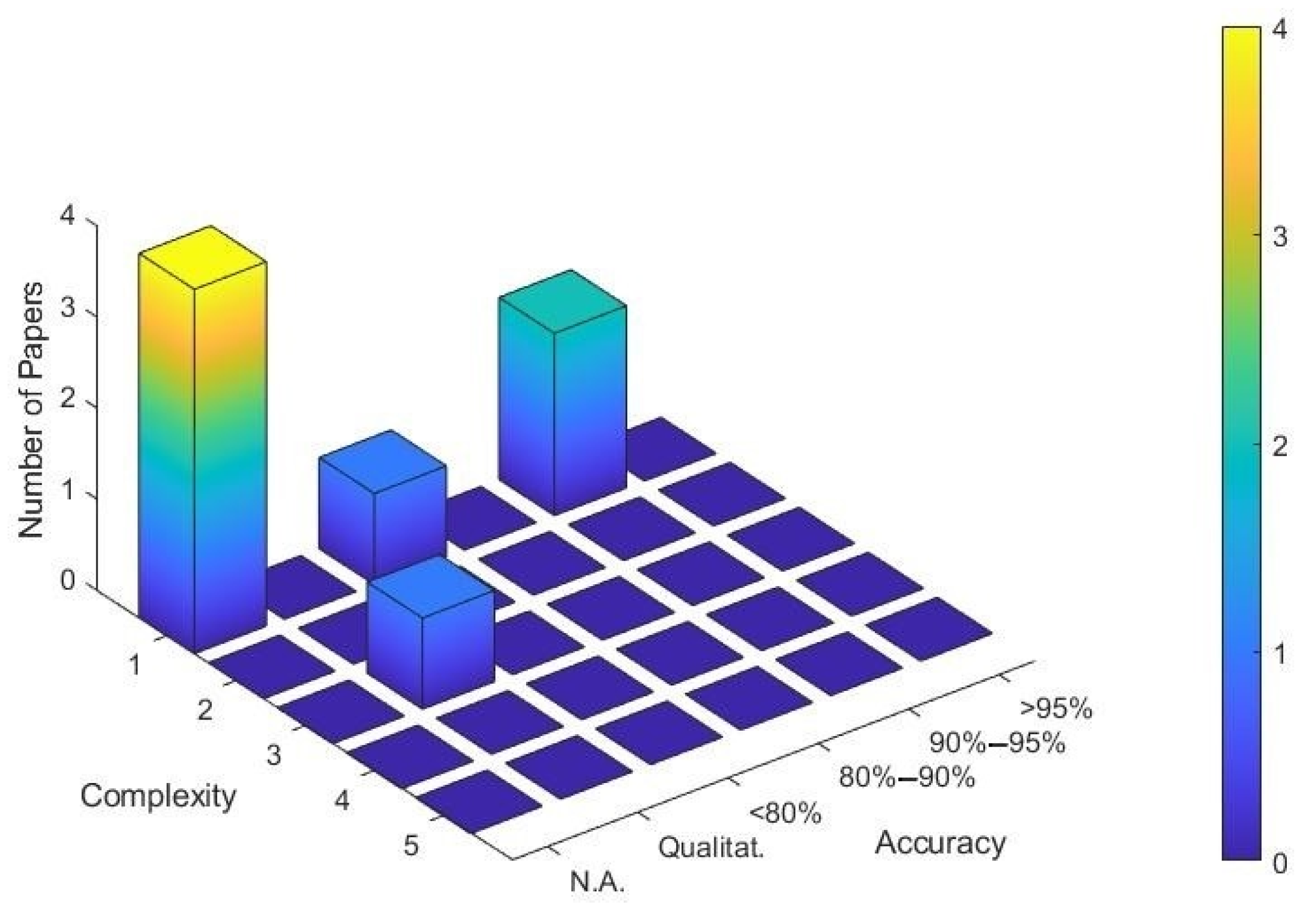
Section 4.2. In the list, nine scientific works, published since 2009, have been considered pertinent for the goal of this paper. In particular, it is possible to notice that seven papers out of nine have been published in the last two years. In addition, six out of nine papers have been experimentally validated but three out of six have been verified only qualitatively. The other three works show that the difference between the CFD analysis and the experimental results differ widely more than 10%. Indeed, in
Figure 1, it is possible to notice that even if the system simulated through meshless approaches can achieve a good level of complexity (generally between 3 and 4), the accuracy of the results is mostly not verified or demonstrated only qualitatively. It is interesting to note that no bearing simulations have been found in the pertinent literature. Moreover, all the simulations were carried out with commercial software. In particular, ParticleWorks™ software was used in [
12,
14,
63] where the MPS method was exploited. In [
64] DPM was used while the SPH was exploited in the other works. Among the others, it is possible to mention the software ANSYS FLUENT, used for example in [
15].
In [
15,
64] pumping systems were studied. More specifically, the two-phase flow (air-oil mixture) in a pump for the aeroengine lubrication was simulated in [
64]. In [
15] meshless approaches were applied in a pump for mineral processing. In [
12,
16] the meshless approaches were exploited for studying the oil flow in ordinary gearboxes.
The target of the analysis performed in [
12,
16] is to simulate the oil flow in gearboxes and the results obtained have been validated qualitatively. Modelling a multiphase gearbox was the goal of [
65] but the results have not validated yet. In [
17,
66], the meshless approaches were used to estimate the churning losses in gearboxes. In [
63] a speed reducer with complex shapes have been simulated.
5.2. Categorization of Relevant Papers Exploiting the Static Mesh Approach
In
Table 2, all the relevant papers exploiting SM approaches are listed and classified. Eight relevant paper emerged. All the papers are published since 2016. It is interesting to note that six papers out of eight aim to study bearings and no results simulating pumps has emerged. In particular, in [
67,
68] it was simulated the grease behavior in ball bearings. Hydraulic losses in rolling bearings due to specific characteristics or components were investigated in [
20,
21,
22,
69].
With respect to the study of the gears through SM approach, it is possible to mention [
70] where the oil jet impingement was studied through the LBM and [
71] where the lubrication characteristics of asymmetric helical gear were investigated.
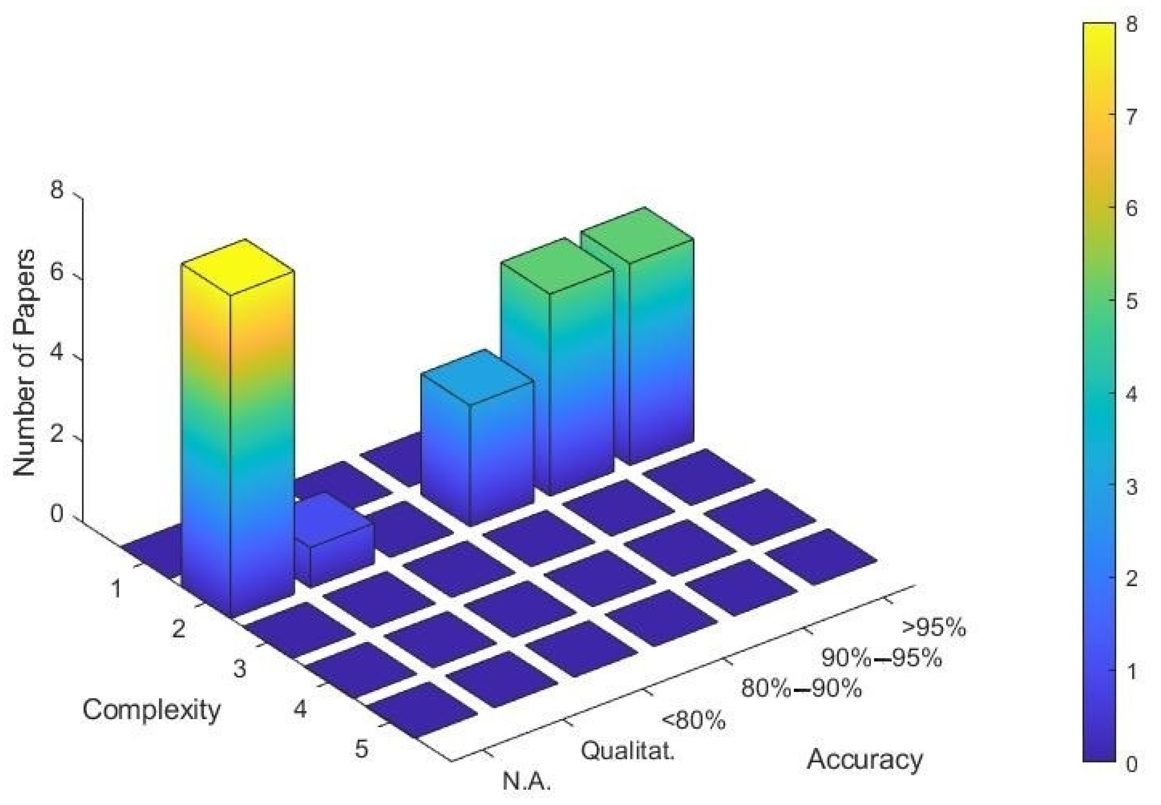
In
Figure 2, it is possible to notice that the accuracy of half of the results is not available. In addition, the figure shows that the level of complexity simulated is generally very low. Only in [
70] the complexity can be considered at level 3. Moreover, it is interesting to notice that only commercial software were exploited. In particular, in [
70] it is used the software XFlow implementing the LBM. ANSYS FLUENT were exploited in [
20,
21] while ANSYS CFX was implemented in [
22,
71].
5.3. Categorization of Relevant Papers Exploiting the Rotating/Multi Reference Frame Approaches
In this section, the results of the paper classification using RRF/MRF approaches are presented. In particular, the classified papers are listed in
Table 3. The literature search highlights 23 pertinent records, published since 2007. Among the 22 total works, 11 deal with gears, eight with pumps, and three with bearings. The most studied phenomenon through this strategy is undoubtedly the windage power losses in gears. Indeed, the windage power losses were studied through RRF/MRF approaches for spur gears in [
23,
24,
25,
72,
73,
74,
75], for bevel gears in [
26,
76] and for a planetary gearbox in [
28]. The study of churning losses for a spur gear exploiting these approaches can be found in [
27].
Through the RRF/MRF approaches different kind of pumps were studied. In particular, centrifugal pumps were simulated in [
77,
78,
79,
80,
81], an axial-flow pump was studied in [
82], and a vortex pump working with highly viscous liquid flow condition was simulated in [
83]. In addition, also the study of a Francis turbine was performed through these approaches [
84].
Table 3.
Classification of the pertinent papers exploiting the rotating/multi reference frame approaches.
Table 3.
Classification of the pertinent papers exploiting the rotating/multi reference frame approaches.
| Paper | Year | Software | System | Target | Validation | Accuracy | Complexity |
|---|
| [23] | 2007 | Comm. | Gears | Forces | Yes | 90%–95% | 2 |
| [82] | 2007 | Comm. | Pump | Fluxes | Yes | Qualitat. | 2 |
| [26] | 2010 | Comm. | Gears | Forces | Yes | >95% | 2 |
| [24] | 2011 | Comm. | Gears | Forces | Yes | >95% | 2 |
| [72] | 2012 | Comm. | Gears | Forces | No | N.A. | 2 |
| [25] | 2012 | Comm. | Gears | Forces | No | N.A. | 2 |
| [77] | 2012 | Comm. | Pump | Forces | Yes | 80%–90% | 2 |
| [73] | 2013 | Comm. | Gears | Forces | Yes | 90%–95% | 2 |
| [29] | 2013 | Comm. | Bearing | Fluxes | No | N.A. | 2 |
| [30] | 2015 | Comm. | Bearing | Fluxes | No | N.A. | 2 |
| [78] | 2016 | Comm. | Pump | Fluxes | No | N.A. | 2 |
| [84] | 2016 | Open | Pump | Both | Yes | >95% | 2 |
| [28] | 2017 | Comm. | Gears | Both | No | N.A. | 2 |
| [85] | 2017 | Open | Bearing | Both | Yes | 80%–90% | 2 |
| [27] | 2018 | Comm. | Gears | Both | Yes | 90%–95% | 2 |
| [83] | 2018 | Comm. | Pump | Both | Yes | >95% | 2 |
| [74] | 2019 | Comm. | Gears | Forces | Yes | 90%–95% | 2 |
| [84] | 2019 | Comm. | Gears | Forces | No | N.A. | 2 |
| [79] | 2019 | Open | Pump | Both | Yes | 80%–90% | 2 |
| [80] | 2019 | Comm. | Pump | Both | No | N.A. | 2 |
| [81] | 2019 | Comm. | Pump | Both | Yes | 90%–95% | 2 |
| [76] | 2020 | Comm. | Gears | Both | Yes | >95% | 2 |
With respect to the bearing simulation through RRF/MRF approaches, it is possible to notice two papers aimed at investigating the oil flow within roller bearings [
29,
30]. However, these two studies were not experimentally validated. On the other hand, in [
85] it is presented the only one experimentally validated work that simulates a bearing. It shows an accuracy between 80%–90%.
In
Table 3, it is possible to notice that three works were carried out through the open-source software OpenFOAM
® [
77,
84,
85]. Therefore, most of the work using the RRF/MRF approaches has been conducted through commercial software. More specifically, ANSYS FLUENT was used in nine works [
23,
25,
26,
27,
28,
30,
76,
78,
83] and ANSYS CFX was exploited in 8 papers [
24,
72,
73,
77,
80,
81]. ANSYS FLOTRAN was used in [
82] while Altair HyperWorks AcuSolve in [
74]. In addition, it is possible to notice that most of the works exploiting open-source software (two out of three) achieved an accuracy of 80%–90% while, exploiting commercial software it is possible to achieve an accuracy generally high, e.g., accuracy >90% for 10 works out of 11 where the accuracy is available and commercial software were used. In
Table 3, it is possible to notice that each relevant paper exploiting the RRF/MRF approaches shows a level of complexity of 2, i.e., semi-transient simulations where the transitory is purely numerical without physical meaning leading to an averaged solution.
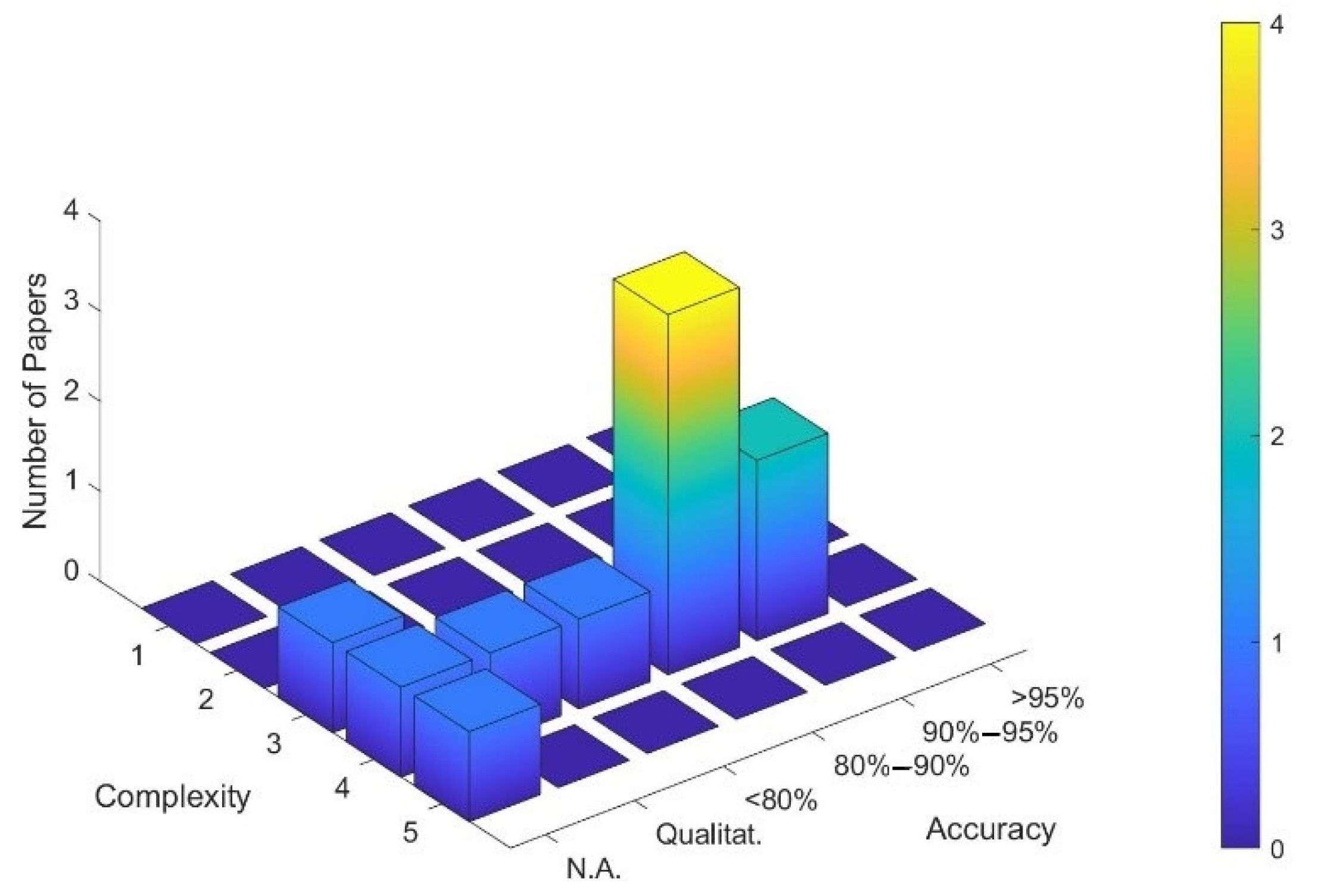
In
Figure 3, it is possible to notice that when the accuracy is available (in 14 papers out of 22) it is distributed in a range from 80%–90% to >95%. More specifically, three papers show an accuracy of 80%–90%, five papers show an accuracy of 90%–95%, and five papers show an accuracy of >95%. However, in many of the pertinent papers the accuracy is not available.
5.4. Categorization of Relevant Papers Exploiting the Rigid Mesh Motion and Sliding Meshes Approaches
The paper exploiting RMM/MSL approaches are summarized in
Table 4. The literature search has highlighted 29 pertinent papers (the highest number of relevant papers using a specific CFD approach). In particular, 11 papers studying gears, 11 papers simulating pumps, and seven papers considering bearings.
With respect to the papers studying the lubrication of gears through RMM/MSL approaches, it is possible to find works aimed at stimulating the oil flow in spur gears [
86,
87] and calculating the power losses in ordinary gears [
32,
88]. The lubrication of vehicle drive axles was studied in [
89,
90,
91] and a tractor transmission was simulated in [
92]. The power losses in planetary gearboxes were investigated in [
35,
93] and the oil jet lubrication for an high speed gear was studied in [
94].
The oil jet lubrication was simulated through RMM/MSL approaches also in ball bearings, e.g., [
95,
96,
97]. The hydraulic power losses in tapered roller bearings were investigated in [
98,
99], in cylindrical roller bearings were studied in [
31], and in ball bearing were simulated in [
100].
Through RMM/MSL approaches several kind of pumps were simulated. In particular, an oil pump was modelled in [
101], a gerotor pump in [
102], a trochoidal-gear pump in [
103], a gear pump in [
104], an electrical submersible pump in [
105], a pump for hemodynamic application in [
106], centrifugal pumps in [
33,
34,
107], a pump mixer in [
108], and a pump as a turbine in [
109].
In addition, in
Table 4 it is possible to notice that 22 papers out of 31 present an experimental validation. It is interesting that more than a third (12 out of 29) of the works implementing the RMM/MSL approaches exploit open-source software. In particular, OpenFOAM
® was used in [
31,
32,
33,
34,
87,
88,
93,
102,
103,
104,
107,
108]. With respect to commercial software, ANSYS FLUENT was used in [
35,
36,
90,
94,
95,
96,
105], and ANSYS CFX was exploited in [
98]. In [
101] was used the commercial software PumpLinx
® by Simerics Inc.
® (Bellevue, WA, USA).
In
Figure 4, it is possible to see that most of the works simulated a level of complexity of 4 (more specifically, 15 works out of 29) achieving an average accuracy of 80%–90%. It is interesting to notice that the RMM/MSL approaches can simulate a level of complexity of 5. However, this level of complexity has been studied only in the bearings. Indeed, these approaches are not able to reproduce the gear meshing and, when it has been applied to planetary gearboxes, the teeth have not been modelled engaged. It is possible to notice that the only study that simulates bearings by applying the RMM/MSL approaches through OpenFOAM
® [
31] has achieved the highest possible level of accuracy.
Table 4.
Classification of the pertinent papers exploiting the rigid mesh motion and sliding meshes approaches.
Table 4.
Classification of the pertinent papers exploiting the rigid mesh motion and sliding meshes approaches.
| Paper | Year | Software | System | Target | Validation | Accuracy | Complexity |
|---|
| [86] | 2008 | Comm. | Gears | Fluxes | Yes | Qualitat. | 3 |
| [108] | 2012 | Open | Pump | Both | Yes | 80%–90% | 3 |
| [35] | 2013 | Comm. | Gears | Both | Yes | >95% | 4 |
| [107] | 2013 | Open | Pump | Fluxes | Yes | Qualitat. | 3 |
| [33] | 2013 | Open | Pump | Fluxes | Yes | Qualitat. | 3 |
| [88] | 2014 | Open | Gears | Both | Yes | >95% | 3 |
| [95] | 2014 | Comm. | Bearing | Both | No | N.A. | 4 |
| [100] | 2014 | Comm. | Bearing | Both | Yes | 90%–95% | 5 |
| [101] | 2014 | Comm. | Pump | Both | Yes | >95% | 4 |
| [32] | 2015 | Open | Gears | Both | Yes | >95% | 3 |
| [94] | 2015 | Comm. | Gears | Both | No | N.A. | 3 |
| [98] | 2015 | Comm. | Bearing | Both | Yes | 80%–90% | 5 |
| [96] | 2015 | Comm. | Bearing | Both | No | N.A. | 4 |
| [93] | 2016 | Open | Gears | Both | Yes | 90%–95% | 4 |
| [89] | 2016 | Comm. | Gears | Both | Yes | 90%–95% | 4 |
| [99] | 2016 | Comm. | Bearing | Both | Yes | 80%–90% | 4 |
| [97] | 2016 | Comm. | Bearing | Fluxes | Yes | 90%–95% | 4 |
| [103] | 2016 | Open | Pump | N.A. | No | N.A. | 4 |
| [87] | 2017 | Open | Gears | Fluxes | No | N.A. | 3 |
| [102] | 2017 | Open | Pump | Fluxes | No | N.A. | 4 |
| [90] | 2019 | Comm. | Gears | Both | Yes | 90%–95% | 4 |
| [91] | 2019 | Comm. | Gears | Both | Yes | 90%–95% | 4 |
| [92] | 2019 | Comm. | Gears | Fluxes | No | N.A. | 3 |
| [109] | 2019 | Comm. | Pump | Both | Yes | 80%–90% | 4 |
| [104] | 2019 | Open | Pump | Both | Yes | 90%–95% | 3 |
| [34] | 2019 | Open | Pump | Forces | No | N.A. | 4 |
| [106] | 2019 | Comm. | Pump | Fluxes | No | N.A. | 3 |
| [105] | 2019 | Comm. | Pump | Both | Yes | >95% | 4 |
| [31] | 2020 | Open | Bearing | Both | Yes | >95% | 5 |
5.5. Categorization of Relevant Papers Exploiting the Overlapping Grids Approach
The literature search has revealed 11 relevant articles using the OG approach. These are reported in
Table 5. It is possible to notice that this approach has been exploited primarily in the study of the gears (10 papers out of 11) and no applications to bearings were found. This result was predictable because the OG approach allows simulating the topological variation of the mesh (as in engaging gears). However, in the bearings, the topology of the mesh does not change because there are always axis-symmetric elements that interact. This approach allows simulating a level of complexity of 5 for the modelling of a planetary gearbox but, in this case, no experimental validation has been performed [
40].
The OG approach have been exploited especially for simulating transmission gears in the aeroengine [
110,
111,
112] and in automotive transmissions [
38,
39,
113]. Moreover, a splash-lubricated gearbox was studied in [
34] and jet-lubricated gearboxes in [
36,
114]. A gerotor pump was modelled in [
115].
It is interesting to notice that OG is implemented by commercial software only. In particular, the commercial software STAR-CCM+ was used in [
36,
39,
40,
114] and FLOW 3D was exploited in [
37,
111,
112]. In
Figure 5, it is possible to see that most of the studies simulate a level of complexity of 4 achieving an accuracy of 80%–90%. In the studies emerged, an accuracy >95% is not observed.
Table 5.
Classification of the pertinent papers exploiting the overlapping grids approach.
Table 5.
Classification of the pertinent papers exploiting the overlapping grids approach.
| Paper | Year | Software | System | Target | Validation | Accuracy | Complexity |
|---|
| [110] | 2009 | Comm. | Gears | Both | Yes | 80%–90% | 4 |
| [113] | 2014 | Comm. | Gears | Both | Yes | 80%–90% | 4 |
| [111] | 2014 | Comm. | Gears | Both | Yes | 90%–95% | 4 |
| [39] | 2015 | Comm. | Gears | Both | No | N.A. | 3 |
| [112] | 2017 | Comm. | Gears | Both | Yes | 80%–90% | 4 |
| [36] | 2017 | Comm. | Gears | Fluxes | No | N.A. | 4 |
| [114] | 2018 | Comm. | Gears | Fluxes | Yes | Qualitat. | 4 |
| [40] | 2019 | Comm. | Gears | Both | No | N.A. | 5 |
| [37] | 2019 | Comm. | Gears | Both | Yes | <80% | 4 |
| [38] | 2019 | Comm. | Gears | Both | Yes | 80%–90% | 4 |
| [115] | 2019 | Comm. | Pump | Both | Yes | 90%–95% | 4 |
5.6. Categorization of Relevant Papers Exploiting the Local Remeshing Approach
In
Table 6, the pertinent papers exploiting the LRA are classified. In particular, 22 articles were considered pertinent with the goal of this study. In the list, it is possible to discern 20 papers that study gears, one paper that simulates a pump, and one paper that simulates a bearing. The study involving the bearing required the use of this approach because the mesh topology could vary due to the thermal expansion of a thrust bearing [
116]. In the table, it is possible to notice that all the simulations have been performed through commercial software. Indeed, the LRA is the implemented in ANSYS FLUENT. In
Figure 6, can be noticed that the level of complexity simulated is mainly 4 and the most recurrent accuracy is >95%. Interestingly, although this method allows the remeshing of very complex geometries, it has rarely been applied to system having a complexity level of 5. Solely in [
52] the LRA was exploited to simulate a planetary gearbox. However, the results were compared only with analytical equations and not with experimental data.
On the one hand, the application of this approach to rolling (rigid) bearing does not bring any advantage. On the other hand, the application of LRA would allow studying cycloidal and planetary systems but it would require an excessive computational effort. A study on a planetary gearset can be found [
117] but, in this study, many geometrical approximations were applied.
Through the LRA entire transmissions have been modelled, e.g., a dual clutch transmission [
118] and a manual transmission [
119]. The oil jet was studied for orthogonal face gear drive [
120], helical gears [
47], and spiral bevel gears [
50]. Spiral bevel gears were modelled also in [
48,
49] to study the splash lubrication and a hypoid gearbox was simulated in [
51]. However, the most studied system with LRA is undoubtedly two engaging spur gears. Indeed, the power losses due to oil squeezing in spur gears were studied in [
42,
121]. The churning power losses in spur gears were investigated in [
122,
123] and in [
124] (where also the windage losses were considered). An overview on the overall hydraulic losses in spur gears estimated through LRA can be found in [
41,
43,
44]. Eventually, the debris particles conveying process in lubricant between gear engagement was simulated in a gear pump in [
125].
Table 6.
Classification of the pertinent papers exploiting the local remeshing approach.
Table 6.
Classification of the pertinent papers exploiting the local remeshing approach.
| Paper | Year | Software | System | Target | Validation | Accuracy | Complexity |
|---|
| [41] | 2009 | Comm. | Gears | Both | Yes | Qualitat. | 4 |
| [117] | 2011 | Comm. | Gears | Fluxes | Yes | Qualitat. | 3 |
| [42] | 2012 | Comm. | Gears | Both | No | N.A. | 4 |
| [122] | 2012 | Comm. | Gears | Both | Yes | >95% | 4 |
| [118] | 2012 | Comm. | Gears | Fluxes | Yes | Qualitat. | 4 |
| [45] | 2013 | Comm. | Gears | Both | Yes | >95% | 4 |
| [124] | 2013 | Comm. | Gears | Both | Yes | >95% | 4 |
| [121] | 2014 | Comm. | Gears | Both | No | N.A. | 4 |
| [119] | 2015 | Comm. | Gears | Both | Yes | 80%–90% | 4 |
| [43] | 2016 | Comm. | Gears | Both | Yes | 80%–90% | 4 |
| [123] | 2017 | Comm. | Gears | Both | Yes | >95% | 4 |
| [44] | 2018 | Comm. | Gears | Both | Yes | >95% | 4 |
| [51] | 2018 | Comm. | Gears | Both | Yes | >95% | 4 |
| [52] | 2018 | Comm. | Gears | Both | No | N.A. | 5 |
| [46] | 2019 | Comm. | Gears | Both | Yes | 90%–95% | 4 |
| [120] | 2019 | Comm. | Gears | Forces | Yes | 80%–90% | 4 |
| [125] | 2019 | Comm. | Pump | Fluxes | No | N.A. | 4 |
| [48] | 2019 | Comm. | Gears | Both | Yes | >95% | 4 |
| [49] | 2019 | Comm. | Gears | Both | Yes | 90%–95% | 4 |
| [116] | 2019 | Comm. | Bearing | Forces | Yes | >95% | 4 |
| [47] | 2020 | Comm. | Gears | Forces | Yes | 80%–90% | 4 |
| [50] | 2020 | Comm. | Gears | Fluxes | No | N.A. | 4 |
5.7. Categorization of Relevant Papers Exploiting the Global Remeshing Approach
The ten scientific papers using the GRA are collected in
Table 7. It is possible to notice that this method is implemented uniquely through open-source software, in particular OpenFOAM
®. As well as for OG and LRA, it is possible to assert that the study of rigid rolling bearing finds no benefits in the application of the GRA. Indeed, the pertinent papers show its application in pumps and gears, i.e., mechanical systems that require the study of topological changes of the computational domain. Most of the papers (9 out of 10) show a validation through experimental results that, in turns, highlights the capability of the GRA to achieve an excellent level of accuracy. This can be visible also in
Figure 7. In the figure, it is clear the capability of this approach to model complex system (level of complexity between 4 and 5) achieving level of accuracy always better than 90%. Indeed, this is the only approach that allows obtaining very good accuracies in the simulation of complex systems, e.g., planetary and cycloidal gearboxes with reasonable computational efforts.
In fact, the GRA was applied for the study of cycloidal gear sets in [
62] and for the study of planetary gearboxes in [
55,
60,
61]. In addition, the hydraulic power losses in engaging spur gears were investigated through the GRA in [
53,
54,
56,
57]. In particular, the great advantages of GRA compared to LRA in terms of simulation time and computational effort are shown in [
53,
54]. The effect of the static pressure on the power dissipation of gearboxes has been investigated in [
56].
With respect to the study of the pumps, the lateral lubricating gap between sliding lateral bushes and spur gears in external gear machines was studied in [
58] and an external gear pump was modelled in [
59].
5.8. General Overview of the Results
In order to have a better overview, the results shown in the previous sections have been summarized in
Figure 8. In particular, in
Figure 8, the number of studies that achieve a specific combination of accuracy of the results and complexity of the modelling can be seen subdivided per each approach. In the figure, it is clear that different approaches tend to perform differently in terms of complexity and accuracy. For instance, the GRA tend to get the greatest levels of accuracy and complexity. The LRA usually achieve a high level of accuracy but it is applied mainly for a medium-high level of complexity. The same level of complexity that can be simulated through OG but, usually, obtaining a lower level of accuracy. RRF/MRF approaches are characterized by a medium-low level of complexity and a wide range of level of accuracy. Through RMM/MSL medium-high level of both complexity and accuracy can be usually achieved. Most of the results concerning SM were not validated and, however, this approach is characterized by a low level of complexity. Eventually, meshless approaches are able to simulate complex system but the results could be accurate only at a qualitative level.
The distribution of the exploitation of approaches among the years are reported also in graphical form in
Figure 9. The trend shows a clear increase of the number of records in the years also thanks to the developments in computer science. In 2019, the number of publication (29 papers) has more than doubled the previous years. Naturally, in 2020 there is a decrease both because this is the current year and, therefore, some publications have not yet been published or indexed in Scopus.
In
Figure 9, it is possible to notice that some approaches such as RMM/MSL and MRF and, to a lesser extent, LRA have been used continuously over the last decade. Other approaches, such as GRA and meshless approaches, are increasing their widespread use, especially in the most recent years. Moreover, the SM approach is used mainly in the most recent years.
In
Figure 10, through a spider diagram, it is shown (for each approach) the number of papers studying specific mechanical system, i.e., gears, bearing or pump. In the diagram, it is possible to notice that almost all the works carried out through remeshing strategies aims at studying gears. Pumps are mainly simulated exploiting RRF/MRF and RMM/MSL approaches. Eventually, components of bearings have been studied through the SM approach or RMM/MSL approaches. In addition, as mentioned in the previous sections, RMM/MSL is the most exploited approach.
Figure 10 clearly shows that OG, LRA, and GRA are almost exclusively applied in the study of gears.
6. Discussion
Results show that in recent years the number of papers involving the study of lubricated mechanical components through meshless approaches has increased. However, even if these approaches are theoretically able to simulate the macroscopic behavior of fluids in very complex mechanical systems, no studies about the lubrication of bearings, or cycloidal or planetary gearboxes have emerged. In addition, the results suggest that the meshless approaches are not yet able to obtain accurate results on power losses for the studied mechanical components.
Different meshless methods have been used to study lubrication problems e.g., MPS, DPM and SPH and all these methods have been used through commercial software e.g., ParticleWorks™ for MPS. Indeed, it should be noted that, in the field of lubrication, this approach has never been applied through open-source software although open-source codes are already available. Future works could aim at using and/or developing open-source codes to study the lubrication of these mechanical components, e.g., roller bearings, or planetary or cycloidal gearboxes.
The SM approach are used for studying mechanical components with a very low complexity and the simulation exploiting this approach are always steady state. This approach can be useful when the objective of the simulation is to investigate the effect of the variation of specific geometric features in the operating condition. Due to the simplicity of this approach, it can be implemented in any CFD software. However, the relevant studies that have emerged have used the SM approach only through commercial software, e.g., ANSYS FLUENT and ANSYS CFX. In addition, although SM is a simple approach, the related works emerged in this research are relatively recent. This may be because with modern calculation powers, it is possible to obtain more accurate results than analytical methods with comparable time. Another possible explanation is that modern solvers allow to simulate fluids with particular properties, e.g., grease or to study physical phenomena, such as cavitation, with very precise spatial resolutions.
The RRF/MRF approaches can carry out solely semi-transient simulations. This approach allows to faithfully simulate rotating components immersed in fluids e.g., a single gear that rotates immersed in oil (or in air) to calculate windage losses. These approaches allows also simulating bearings but they are not suitable for simulating engaging gears. These approaches can be implemented in both open-source and commercial software, e.g., ANSYS FLUENT, ANSYS CFX, ANSYS FLOTRAN, and Altair HyperWorks AcuSolve. The results show that for RRF/MRF approaches, commercial software can achieve better accuracy than open-source software. However, many studies have not been experimentally validated. Therefore, future research should propose to validate the results achievable through these approaches. Moreover, the capabilities of open-source software to simulate through RRF/MRF approaches should be improved.
With respect to the RMM/MSL approaches, results clearly shows that RMM/MSL are the most exploited and established approaches in the study of lubrication of mechanical components. These approaches are the most appropriate to simulate the real kinematics of rolling bearings and centrifugal pumps. In addition, these approaches are also appropriate to simulate a single gear that rotates immersed in one or more fluids. However, in order to be applied to engaging gears, considerable geometrical simplifications have to be introduced.
The accuracy of results achievable with RMM/MSL approaches is around 90%–95%. Simulations that reach an accuracy >95% are more common than those that reach an accuracy <90%. These approaches can be successfully implemented in open-source software such as OpenFOAM®. The commercial software emerged from the research are mainly ANSYS FLUENT, ANSYS CFX, and PumpLinx® by Simerics Inc.® (Bellevue, WA, USA). It is interesting to notice that only through OpenFOAM® it has achieved an accuracy >95% for the simulation of bearings by applying the RMM/MSL approaches.
The OG is mainly exploited for simulating engaging gears and it was applied in the lubrication field solely through commercial software. Indeed, it is possible to notice that the two commercial software emerged in this research are STAR-CCM+ and FLOW 3D that have not emerged for the others approaches. However, even if this approach is able to simulate complex kinematics, the achievable accuracy of the results is generally around 80%–90%. Future studies should focus on applying available open-source software and/or developing new code capable of improving the accuracy of results without worsening the computational effort required.
The LRA is a very versatile approach and it is appropriate to reproduce any topological change of the computational domain. It is important to remark that the LRA is implemented in the commercial software ANSYS FLUENT. In addition, this approach usually achieves a high accuracy (errors <10%). However, LRA requires a significant computational effort and it has rarely been applied to study very complex mechanical systems, such as cycloidal or planetary gearboxes. The limitation of the LRA are overcome by the GRA. Indeed, this approach, implemented through the open-source software OpenFOAM®, extremely shortens the computational time of the LRA with the same capability of managing the topological variation of the computational domain. In addition, GRA shows that it is capable of better accuracy (errors <5%) than the LRA. However, the GRA is an approach that can be applied uniquely through OpenFOAM®. Therefore, carrying out simulations through the GRA requires a very good knowledge of the OpenFOAM® software. This requirement could discourage the less experienced user in applying GRA. Therefore, future developments of this method should focus on simplifying the application of GRA, also through the development of specific graphic interfaces.
In the present review, articles that study journal bearings were not considered relevant because they do not present particular difficulties in terms of mesh handling and/or complex kinematics. However, these components are largely studied through CFD analysis and some exception can be found in the literature. It is worth mentioning the following CFD study targeting to simulate journal bearings. In [
126] an elliptic bore bearing was simulated through the LRA. The simulation of magnetorheological fluid and Bingham lubricant in the lubrication of journal bearing using CFD was carried out, respectively, in [
127] and [
128]. The effect of surface texturing in journal bearing were studied through CFD in [
129]. In [
130] the cavitation in journal bearing was studied through OpenFOAM
®. Therefore, a review of the CFD applied to journal bearing could be carried out in future studies.
Eventually, the present research have been conducted by querying exclusively the Scopus database in the fields of title, abstract and keywords. This means that papers that were not indexed Scopus or those that did not meet the search criteria were not included in the results. For example, relevant articles could be found in the proceedings of the international conference on gears [
131] which, however, is not indexed in Scopus. An additional example can be found in [
132]. This paper can be considered pertinent to the review but the keywords CFD or computational fluid dynamics do not emerge neither in the title nor in the abstract nor among the keywords. Therefore, this contribution did not appear among the results.
7. Conclusions
In the present paper, a literature analysis has been performed through the Scopus database. In particular, the most pertinent paper in which a CFD approach have been exploited to study the lubrication in specific mechanical components/systems were collected and classified. The classification of the emerged 109 pertinent papers have been performed based on eight variables, i.e., (1) the year of publication, (2) the CFD approach, (3) the software type, (4) the simulated system, (5) the target of the simulation (6) the experimental validation (7) the accuracy of the results, and (8) the complexity of the modelling. The numerical results have been elaborated in order to present the strengths and limitations of the various approaches objectively.
In particular, for each CFD approach, it was shown the number of studies that deal with a specific complexity in the modelling and obtain a specific accuracy of the results. For example, this kind of results shows that GRA is capable of simulating very complex systems (e.g., cycloidal and planetary gearboxes) obtaining particularly accurate results. While OG is mainly applied for simulating medium-high complex system (e.g., engaging spur gears) obtaining generally medium-high accuracy (80%–90%). Very good levels of accuracy and complexity can be achieved also through LRA and RMM/MSL approaches. However, LRA is able to simulate the engaging gears while RMM/MSL approaches are not.
The lubricated mechanical components that have been considered in the present paper are bearings, pumps and gearboxes. Considerations on the appropriateness of the use of each CFD approach on the type of mechanical system analyzed have been discussed. In particular, OG, LRA, and GRA are the most appropriate methods to simulate engaging gears (in gearboxes and in gear pumps) lubrication since they are able to manage (even if with different levels of accuracy of the results) the topology variation of the computational domain. RMM/MSL approaches proved to be the most appropriate approaches to simulate rolling bearings (in their complexity) and centrifugal pumps. While meshless approaches can be exploited to study the macroscopic fluxes in complex lubricated mechanical systems.
In the present research, several software have emerged and discussions on open-source and commercial software were open up. In particular, the most popular open-source software is undoubtedly OpenFOAM® that enables the GRA and allows the implementation of the other approaches with the exception of Meshless approaches. In some cases, OpenFOAM® has led to generally more accurate results than commercial software in the implementation of specific approaches (e.g., RMM/MSL). In other cases, the approaches implemented through commercial software were more accurate (e.g., RRF/MRF).
Naturally, the results presented in this paper represent a general view of what has been simulated and published to date. Therefore, the limitations of each CFD approach, which have been exposed in this article, may be “hopefully” overcome in the future through improvements that, to date, the authors have not been able to catch.

