Abstract
Nowadays, increasing attention is being paid to techniques aimed at assessing a subject’s ability to maintain or regain control of balance, thus reducing the risk of falls. To this end, posturographic analyses are performed in different clinical settings, both in unperturbed and perturbed conditions. This article presents a new Hardware-In-the-Loop (HIL) equipment designed for the development of an automatic perturbator for postural control analysis, capable of providing controlled mechanical stimulation by means of an impulsive force exerted on a given point of the body. The experimental equipment presented here includes the perturbator and emulates its interaction with both the subject’s body and the operator performing the test. The development of the perturbator and of the entire HIL equipment is described, including component selection, modeling of the entire system, and experimentally verified simulations used to study and define the most appropriate control laws.
1. Introduction
Balance control is fundamental for the performance of many everyday life activities. The complex systems controlling balance may be significantly affected by certain pathologies as well as by aging, and hence it is critically important to develop techniques aimed at objectively evaluating the skills of a subject to maintain balance or to regain it when subjected to a perturbation. Clinicians typically perform balance analyses in static or dynamic posturographic trials. The latter option requires that an adequate external perturbation be delivered to the patient, to evoke a postural response of sufficient magnitude. Typically, mechanical perturbations are imparted by direct application of a force to the body of the subject [1,2,3,4,5,6] or by sliding and tilting the base of support [7,8,9,10,11], as widely described in the literature. However, a system for postural perturbation should also allow for selecting magnitude, point of application and direction of the stimuli, to better fit the specific clinical purpose and patient conditions, but these features are not often guaranteed by the available technology. Current clinical protocols often lack standardized procedures to assess postural control function under dynamic condition. Moreover, they mostly rely on qualitative and subjective assessment. Unstable surfaces are just one of the possible challenges to balance maintenance. Unexpected impact forces to the body, as may be provided by collisions with other people and moving objects, are a frequent cause of falls in many sports activities, working conditions, and in everyday life. Balance perturbations due to body collisions elicit different postural reflexes and body reactions than surface displacements, but have been poorly investigated, possibly also due to the lack of adequate testing devices which account for the individual physical parameters of the subject body. In particular, the same perturbation can stress a human body in different ways depending on its height, weight, and inertia around affected joints. In order to achieve a standardized scalability of the perturbation, it is particularly relevant to develop techniques and systems capable of generating customized and accurate stimuli to subjects with different anthropometric characteristics. For this reason, our work has focused on the development of a mechanical perturbator device with these characteristics, which can operate autonomously or possibly in collaboration with other systems, for example based on a mobile support base, to provide even more complex patterns of perturbation, if required by the specific clinical investigation.
Besides the perturbation system, posturography requires appropriate systems of sensors to detect and record the body response, consistent with the planned analysis. Typically, postural responses can be described using kinetics and/or kinematic means, as well as by the analysis of muscular activity, as detected by electromyography [12]. However, among the several measurements available, the ones related to the displacement of the Center of Pressure, defined as the instantaneous position of the mean of the base of support reactive forces to the subject’s weight, are commonly used to analyze postural response both in static and in dynamic condition [5,7,9,13,14,15,16]. In addition, analyses based on 3-D motion capture are also performed to study the movement of the human body during posture recovery by means of optoelectronic systems [17,18] and inertial measurement units (IMUs) [19,20,21,22]. All these data may be finally correlated with the perturbation to render an objective assessment of the subject’s postural control. Models of postural control systems are also currently implemented to support the study of postural reactions [2,23,24,25,26]: these are generally described by the combination of an active (neuro-muscular) and a passive (inertial and viscoelastic) response, the former being particularly affected by aging or neuro-muscular diseases.
Human–machine physical interaction is one of the most relevant topics in modern robotics, being strategic in many applications, e.g., safety contacts in collaborative robots [27,28,29], tele-manipulation tasks [30], techniques for robot-aided rehabilitation [31,32] or surgery [33]. Due to the different complexity of these applications, several control techniques for contact force regulation have been developed, with different performance and specifications. In all these applications, it is fundamental to monitor contacts between the machine and the human being. This can be addressed by both passive strategies (e.g., by endowing a mechanical structure with compliant elements) and active control strategies. In the latter, it is necessary to implement monitoring devices and actuators to control in real time the entity of the interaction force. Some examples of active control architectures developed for contact force regulation are hybrid force/position [34] and impedance or admittance controllers [35,36]. In the first architectures, the system is shifted from a position reference to a force reference when a contact force is detected over a specific threshold. On the other hand, impedance and admittance control consists of the regulation of mass, stiffness and damping values associated with the overall mechanical impedance of the system under analysis. Impedance control focuses on trajectory tracking, whereas admittance control is based on a force reference. In addition to the aforementioned techniques, more complex control schemes have been developed and can be found in the literature [37,38].
Control architectures can rely on traditional linear controllers as well as on more refined control strategies as predictive control or model-based robust control [39,40]. Although the latter accounts for any non-linearity in the system, thus theoretically providing improved performance with respect to simpler linear controllers, a more complex formulation of the control logic can be particularly demanding, and the efficiency of the result strictly depends on the accuracy of the modelling of the plant. Moreover, these techniques often rely on additional data relating to the state of the system, thus requiring a larger number of transducers as well as the development of methodologies aimed at the estimation of unknown quantities that cannot be easily measured [41].
This paper describes a new test-bench conceived for the development of an automatic perturbator aimed at providing a pre-set impulsive contact force to a subject, for clinical evaluation of his postural control ability. The perturbator is based on a linear pneumatic actuator controlled by means of two flow proportional valves. The contact force which originates from the interaction between the perturbator and the subject must be regulated with very demanding features in terms of high dynamics and accuracy, since it must interact with the neuro-sensory apparatus of the subject. An analytical model of the human–machine interface, which is described in detail, supports the Hardware-In-the-Loop (HIL) design. The behavior of the model was compared with experimental data collected from the test-bench. The objective of this work is to show that the proposed HIL system enables an extensive design of the automatic perturbator by appropriate selection of pneumatic components and sensors with the final aim to optimize the performance of the system in terms of force control accuracy. Moreover, the automatic perturbator was tested in a realistic environment, thanks to the ability of the HIL equipment to reproduce the main conditions of a typical dynamic posturographic trial.
2. Materials and Methods
2.1. The Automatic Perturbator (AP)
The AP shown in Figure 1 was conceived for the generation of mechanical perturbations to human subjects with the main objective being to analyze postural responses in normal subjects and specific patient cohorts. It consists of six fundamental parts, as shown in Figure 1.
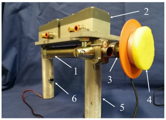
Figure 1.
The automatic perturbator (AP) with its main components: 1. double acting cylinder; 2. two three-way flow proportional valves; 3. uniaxial load cell; 4. end pad for interface with subject; 5. operating handles; 6. trigger button.
The main features of the AP were outlined in previous works [42,43]. It is based on a double acting linear pneumatic actuator, mounted on an integral frame with two handles, which are used by an operator to select the point of application and the direction of the perturbation. The latter must be scalable and adaptable, as well as accurate and repeatable in order to allow for selective and unbiased exploration of the postural control system parameters. Given the simple architecture of the device, the possibility to exert multiple perturbations at the same time (with multiple APs) or to opt for different configurations (such as a fixed or handled AP) represents a significant step forward in perturbators design. Regarding the characteristics of the perturbation, this is an impulsive contact force with short duration (50–250 ms) and limited amplitude of about 50–100 N. The duration should be short enough to limit the overlapping with the active neuro-muscular response of the subject, and the maximum amplitude should be significant enough to evoke a relevant response while avoiding risk to the subject or evoking a ‘step compensation’, a strategy used by human beings in order to avert the risk of falling. Since in the present context, evaluation of the response involves the calculation of the Center of Pressure (CoP) displacement relative to the base of support, the test is conducted while the subject stands on a force platform. The operator is typically positioned behind the subject, to avoid anticipatory control actions (see Figure 2).
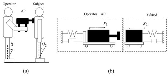
Figure 2.
(a) Configuration of a dynamic posturographic trial, ϑ1 and ϑ2 refer, respectively, to the oscillations of the operator and of the subject about the respective ankle joints; (b) modelling of operator’s and subject’s motion through linear translations x1 and x2.
2.2. The Test-Bench
In order to investigate the performance of the AP under actual operating conditions, the “Hardware-In-the-Loop” (HIL) approach was adopted, based on the integration of the AP in a specific bench capable of emulating its interaction with the operator and with the subject on trial, as shown in Figure 2. An experimental bench, used in previous works on the same topic [42,43], was prepared for testing several versions of the AP. An accurate analytical model of the whole system was derived. The simulations of the dynamic behavior of the model were aimed both at the design of the AP and its control, and at the definition of the most effective characteristics of the same experimental bench.
Numerous analytical models of the human body in posturographic trials have been reported in the literature, with various levels of complexity [44,45]. In such models, the subject’s response may be considered as the sum of a passive and instantaneous part, strictly correlated with the body mechanical impedance, and an active part, due to the intervention of postural motor reflexes, taking place after a given latency period. By designing the HIL equipment, only the passive part of the response was considered. Noteworthy, it is impossible to practically emulate the active one, which is strictly subject-dependent. To represent the passive response in the case of large perturbations, multi-segmental modeling would be indicated, since the evoked postural response likely affects different body segments. Since in our posturographic trials the perturbations given to the back of the subject were of limited magnitude, thus producing small oscillations of the body in the sagittal plane at most, the observed response could be simulated in the equipment by a simple 1-degree-of-freedom (DoF) mechanical impedance, in which the body is modeled as a single link inverted pendulum rotating around the ankle joint axis and provided with viscoelastic rotational stiffness. The same considerations can be applied to the operator, who can be emulated in the equipment by a second 1-DoF mechanical impedance. Since the angular oscillations of both subject’s and operator’s bodies were small, in the model as well as in the test bench, they were considered and realized as linear translations, like the motion provided by the actuator integrated in the perturbator (see Figure 2).
Figure 3 shows the CAD model and actual HIL equipment specimen, whose component details are reported in Table 1. The pneumatic actuator of the AP (11) and an impacted mass (8), which represents the subject, are placed on two independent plates, (12) and (7), respectively, which slide on linear guides (9) by means of carts (13) and are connected to the fixed frame by means of viscoelastic dampers (1), which respectively model the passive reaction of the operator and of the subject. The two valves (2) are placed just above the cylinder in order to shorten the pipes and hence to improve the dynamic response of the actuator. The potentiometers (6) are linked in parallel to the viscoelastic dampers and are used to measure the absolute position of cylinder body and mass. The laser sensor (10) is fixed to the body of the cylinder and is used to measure the cylinder stroke. A load cell (5), along with its support (3), is fixed to the rod end and is integral with the target of the laser sensor (4) as well as with the striker (15) placed at the end of the perturbator.
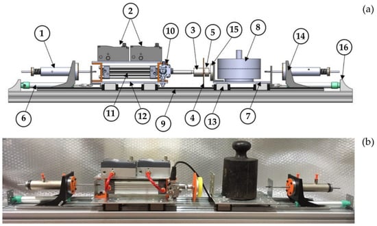
Figure 3.
CAD model (a) and specimen (b) of Hardware-In-the-Loop (HIL) equipment.

Table 1.
Details of the HIL equipment.
The dampers allow a limited motion of about 30 mm of the perturbator and of the stricken mass, and they can be regulated in order to adjust their stiffness and damping coefficients. The most important components of the perturbator are the pneumatic actuator and the two proportional valves. In order to individuate the best configuration, two different commercial low-friction cylinders (Ca and Cb) and two models of valves (Va and Vb) were mounted and tested in our equipment:
- Cylinder Ca: ISO 15552 model (Metal Work S.p.A., Italy); stroke: 120 mm; bore: 32 mm; weight: 3 kg; moving mass: 0.18 kg; provided with Nitrile Butadiene Rubber seals;
- Cylinder Cb: MQMLB25TFH-100D model (SMC Corporation, Japan); stroke: 100 mm; bore: 25 mm; weight: 2.7 kg; moving mass: 0.15 kg; a metal seal ultra-low friction cylinder with minimum working pressure 0.005 MPa;
- Valve Va: 3AF2 model (CKD Co. Ltd., Japan); pressure range 0–10 bar; max conductance 1.97 × 10⁻⁸ (Nm3)/(sPa); critical ratio 0.14; dead band 0.5 V;
- Valve Vb: LRWD2-34 model (Camozzi Automation S.p.A., Italy); pressure range 0–10 bar; max conductance 1.68 × 10⁻⁸ (Nm3)/(sPa); critical ratio 0.36; dead band 0.2 V.
3. Analytical Model of the HIL Equipment
3.1. The Mechanical Impedance of the Subject and the Operator
The physical model of the HIL equipment is depicted in Figure 4. The interaction with the operator who handles the device is taken into account by a viscoelastic impedance (k1 and β1) connecting the AP to the fixed frame. The human subject can be also assumed as a second mechanical impedance (M2, k2 and β2), thus emulating only the passive response of the human body. The mechanical characteristics of the end striker, combined with the properties of tissues in the contact area, are represented by constants k3 and β3, which have been defined with a Kelvin–Voigt model. M1 and m are, respectively, the masses of perturbator’s body and of piston + rod. G1 and G2 are the air flow rates entering the cylinder’s chambers, regulated by three-ways flow proportional valves V1 and V2. All parameters used in the HIL equipment model are listed in the nomenclature of Table 2.
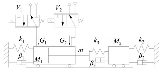
Figure 4.
Sketch of the HIL equipment model.
Table 2.
Nomenclature of parameters of HIL equipment model.
3.2. Proportional Valves
The flow proportional valves are modeled according to the ISO 6358, thus they work as pneumatic nozzles characterized by a sonic conductance C and a critical ratio b. Considering PA and PB, respectively, as the upstream and downstream absolute pressures, and ρ0 as the air density at 25 °C, the flow rate G was calculated as:
Equation (1) is used to calculate the flow rate through each valve: it is considered positive when the flow enters a cylinder’s chamber, and vice versa. The conductance C is not constant, but depends on the sectional area, which can be varied by means of a command signal. Assuming the variation of the conductance linear with respect to the voltage command Vref, the following simplified relation is considered:
in which Kv is the static flow gain of the valve, equal to:
To consider the dynamic effect of each valve on the system, a first order dynamics was assumed, as reported in Equation (4):
3.3. Pneumatic Cylinder
Each chamber of the double acting pneumatic cylinder is modeled as a variable volume V, filled with air with density ρ, according to Equation (5):
In Equation (5), Gin is the flow at the inlet, whereas Gout is the flow at the outlet. Solving Equation (5) for each chamber, assuming that the variation of volume only depends on the stroke of the piston, yields:
The subscript 1 and 2 refer, respectively, to the rear and front chamber of the cylinder, while x3 is the relative position of the piston rod with respect to the cylinder barrel, starting from the central position.
The dynamics of the piston rod is described by Equation (8), which refers to Figure 5:
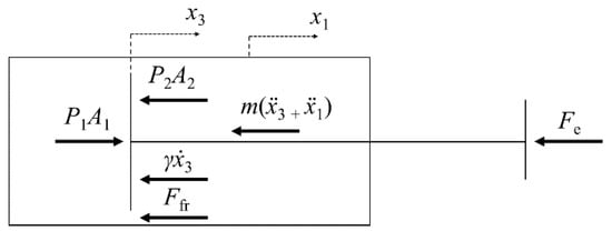
Figure 5.
Forces acting on the piston rod; x1 is the absolute displacement of the cylinder body, and x3 is the relative position of the piston rod with respect to the cylinder.
In Equation (8), x1 is the absolute displacement of the cylinder body; thus, x1 + x3 is equal to the absolute position of the piston rod. Fe is the external force acting on the piston rod, given by the contact between the perturbator and the subject. The dynamics of the cylinder (Figure 6) is expressed by the following equation:
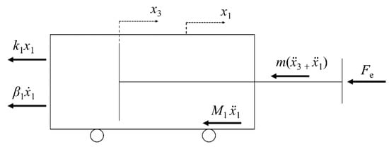
Figure 6.
Forces acting on the cylinder; x1 is the absolute displacement of the cylinder body, and x3 is the relative position of the piston rod with respect to the cylinder.
The external force acting on the piston rod is related to the compression of the interface (buffer), described by the Kelvin–Voigt model, during the impact phase. The equilibrium of the end striker at the interface (Figure 7) is expressed as:
in which dx is the initial distance between the rod and the stricken body, whose displacement is x2.
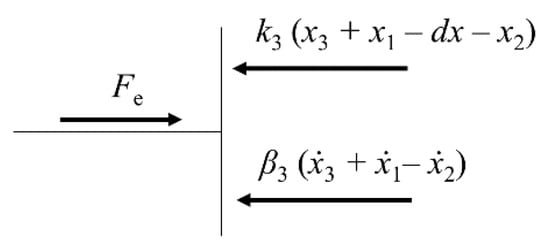
Figure 7.
Forces acting on the end striker.
3.4. Stricken Body
Considering the forces acting along the direction of the perturbation, the dynamics of the stricken body, modeled as a 1-DoF mechanical impedance (see Figure 8), is given by:
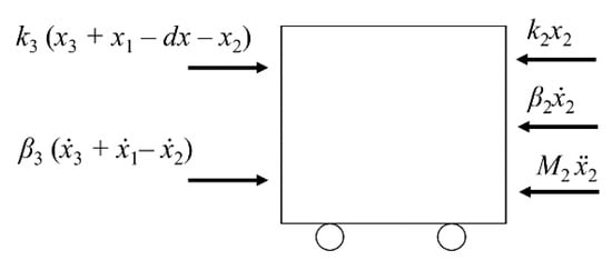
Figure 8.
Equilibrium of the stricken body.
4. Control Strategies of the HIL Equipment
4.1. AP Control Architecture
A scheme of the AP control architecture is depicted in Figure 9. Preliminary analyses [46] performed by the authors on healthy subjects by means of a manual perturbator (MP) highlighted a direct correlation between CoP displacement and the impulse of the contact force, i.e., the integral of the force over time. This correlation was significantly higher than that calculated between the CoP displacement and the peak of the force. Moreover, the duration of the force impulse had to be limited to 50–250 ms, the time during which a passive rather than a passive + active response of the body is anticipated. In terms of accuracy and dynamic response, this is a high demand for the control system, especially when the high nonlinearities and low dynamics typical of pneumatic systems are considered.
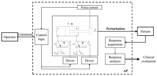
Figure 9.
AP control architecture.
Basically, the AP must track a given reference profile of the contact force, with particular focus on the desired value of the force impulse. As described in [42], the control logic is based on a state-machine architecture, with the sequence of four phases (idle, approach, strike, return) triggered by an external command. A scheme is reported in Figure 10.
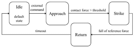
Figure 10.
High level control logic.
The only feedback signal used to perform the force control during impact is provided by the load cell, whereas the motion of the piston rod during approach and return phases (i.e., before and after the contact) could be controlled in open or closed (e.g., by position or velocity feedback) loop. In any case, it is essential to select the appropriate values of the valves’ command signals in order to perform fast transients. The control logic enables the switching between motion control phases and the force control strike phase, which is based on a simple PI controller. The logic is implemented in Simulink® (The MathWorks, Inc., Natick (MA), USA), Stateflow® toolbox, and directly uploaded on a Real-Time Target Machine (dSPACE®, Paderborn, Germany) used for data acquisition and control (200 Hz sampling frequency).
The dynamics of the system, relevant for allowing precise timing of the perturbations, is taken into account by selection of pneumatic components with proper characteristics: low friction for the cylinder, high flow coefficient for the valves. To shorten the length of the pipes, the valves are placed on a frame integral with the actuator, hence they are part of the AP which is maneuvered directly by the operator. For this reason, the components have to be as lightweight as possible. In the tested configuration, the overall weight of the AP was about 3 kg.
4.2. Control Logic Implementation
The control architecture has been developed with reference to the HIL system model of Figure 4. The control system comprises of four subsystems as shown in Figure 11:
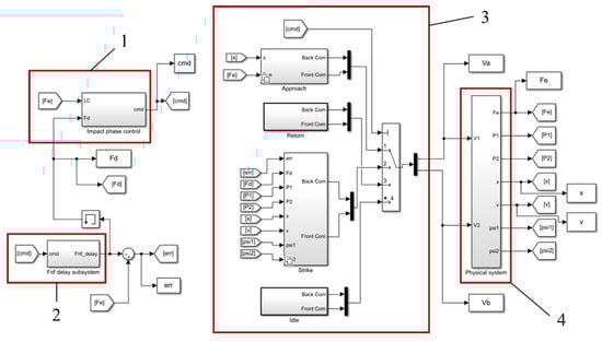
Figure 11.
Control architecture of the system.
- control system of the impact phase;
- control system of the desired force profile;
- selection of operative phases;
- model of dynamic system.
The subsystem 3 regulates the complete process of perturbation that is composed of four phases. The four phases are:
- Idle: the voltage of each valve is reduced to zero. It is the starting condition of the whole system;
- Approach: the rear chamber of the actuator is supplied while the front chamber is discharged, to move the piston rod from the initial retracted condition towards the subject’s mass;
- Strike: a PI controller is used to modulate the valves’ command signals in order to reduce the difference between the desired force (set) and the feedback signal from the load cell;
- Return: the actuator’s front chamber is supplied and the rear chamber is discharged to perform the high speed retraction of piston.
The logic of the control system is based on the concept that only one phase should be active at the same time during the process. The start signal shifts the system from the Idle phase (I) to the Approach phase (II), in which the piston is extended. If the measured contact force exceeds a pre-set threshold, the system shifts into the Strike phase (III) and performs the contact force profile tracking. The Return phase (IV) is activated when the force signal drops below a defined threshold. Following phase IV (Return), a timeout control forces the system to return to phase (I) within few seconds.
The reference force generation block allows the user to set customizable profiles, in terms of shape, amplitude and duration. For instance, the impulse could be set as a constant signal with a predefined level and duration, or as a ramp to reduce the dynamics of the force error signal. The model is able to detect when the contact between perturbator tip and environment actually occurs; this is verified when the condition in Equation (12) is true:
where x1, x2, and x3 are, respectively, the displacements of the cylinder frame, of the subject, and of the piston with respect to the cylinder frame (see Figure 5, Figure 6 and Figure 8). Since the actual control of HIL equipment was realized on a dSPACE® Real-Time target system, programmed directly in Simulink® Real-Time, the model control logic was implemented in the same environment.
A laser sensor (component 10, in Figure 3) was used for real time detection of the x3 displacement; using this information, by means of a closed-loop motion control, it is possible to impose the striker speed at the impact. The difference between a desired velocity value and the actual velocity calculated from the sensor output is used by a PI controller to provide the command signal for the valves’ drivers.
5. Simulations
The most important result of the simulations is the plot of the force vs. time comparing the reference force with the actual force imparted by the perturbator to the stricken mass in several combinations of pneumatic actuators (Ca and Cb) and proportional valves (Va and Vb). Moreover, some conditions, like the effect of a different initial distance between the end striker and the stricken mass on tracking accuracy, have been investigated. Some significant output such as the tracking error (difference between actual and desired force during phase III), the actual force impulse, i.e., the integral over time, and its difference with respect to the desired impulse (accuracy error), were calculated in each simulation. The parameters required to run the model (Table 2) were set according to datasheets (for valves and actuators) and data obtained from characterization of the test-bench (e.g., for the dampers). Unknown parameters, such as the friction force on the piston rod, were estimated by iterative tuning of the model, in order to match the behavior observed during experimentation.
Simulations have been performed with several values of the proportional and integral gains of the PI controller, kp and ki. In general, by raising kp, an increase in accuracy error and a decrease in tracking error were observed. Moreover, the impulse value was significantly affected by variation of kp. In particular, kp values between 0 and 20 provided the most significant changes in the impulse. By means of an iterative procedure, it was possible to individuate the value of kp = 5 as a good trade off.
In Figure 12a, a comparison between the performance provided by cylinders Ca and Cb is shown. The simulation was conducted at fixed constrains (both dampers locked). The behavior with cylinder Cb seemed to be more reactive, probably because of the lower friction given by metal seals rather than NBR seals of Ca. These results were obtained considering the characteristics and response time of the Vb type valves.
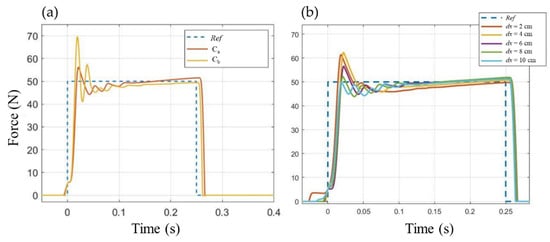
Figure 12.
Evaluation of force tracking accuracy (fixed constraints, desired impulse duration = 250 ms, kp = 3.1, ki = 23.9, valve Vb); Ref refers to the reference force profile. (a) Comparison of performance provided by cylinders Ca and Cb; (b) influence of initial distance dx between perturbator tip and stricken mass, using cylinder Ca.
Another point of interest was the effect of the initial distance between the load cell and the stricken mass. Piston speed at the impact can affect the accuracy of the force tracking during phase III. In a clinical environment, it would be impractical to ask the operator to maintain a fixed value of initial distance between perturbator and subject. Figure 12b shows the results for an initial distance dx variable from 0.02 to 0.1 m, using cylinder Ca. As shown by the plots, the performance of the force tracking is largely unaffected by the different initial positioning of the perturbator with respect to the subject, proving the reliability of our control solution.
6. Experimental Trials
In the model simulations, real-time control of the piston velocity allowed accurate and reliable force tracking. In our previous works [42,43], the AP was driven during phase II in open loop, hence valves’ command signals had to be finely tuned to achieve the desired velocity at impact. However, this control strategy did not provide a reliable behavior, especially when the initial distance between striker and stricken body changed significantly. Therefore, experimental trials carried out with the test-bench were primarily aimed at verifying the effectiveness of motion closed-loop control and eventually the confirmation of the results outlined in Figure 12b. Moreover, it was crucial to test the force tracking performance under different selected components (valves and cylinders).
A comparison between the performance of cylinders Ca and Cb is presented in Figure 13a–b when Vb valves were selected. Each plot shows five consecutive perturbations in fixed constraints configuration (i.e., both AP and stricken body carts locked). Consistently with simulations of Figure 12a, the two cylinders behaved similarly, with comparable performance in magnitude and impulse accuracy, as well as in rise and fall time. Oscillations in the force signal were observed during phase II just before impact (t = 0, Figure 13), likely related to inertial effects on load cell and connected masses. Those oscillations were smoothed out in the following trials, when the piston motion was closed loop controlled during phase II (Figure 14 and Figure 15, at the bottom). As shown in Figure 13c, valves Va behaved significantly worse than Vb, with the latter demonstrating better dynamics while allowing a more accurate behavior of the contact force profile for lower duration of the impulse. Some differences were highlighted also in the switching phase from phase II to III, where the Va valves seemed to be more sensitive to sudden variations in the command signal. However, this result confirms the need for high flow rate and short response time in order to meet the performance requirements of the application.
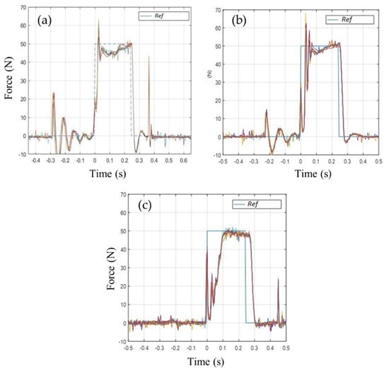
Figure 13.
Experimental force tracking, with fixed constraints and open loop control during phase II. (a) Cylinder Ca and valve Vb; (b) cylinder Cb and valve Vb; (c) cylinder Cb and valve Va. The square waveform in each plot is the reference force profile Ref. Each plot shows five consecutive perturbations.
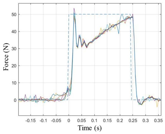
Figure 14.
Experimental force tracking, with viscoelastic constraints and closed loop control during phase II. Cylinder Cb and valve Vb. The square waveform is the reference force profile. Six consecutive perturbations are shown.
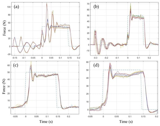
Figure 15.
Experimental force tracking, with viscoelastic constraints, cylinder Cb and valve Vb. Open-loop motion control (a–b) and closed loop motion control (c–d) during phase II. Initial distance dx: 0.05 m (a–c), 0.08 m (b–d). The square waveform in each plot is the reference force profile. Each plot shows six consecutive perturbations.
As shown in Figure 13, the system demonstrated a good tracking accuracy in fixed constraints configuration. Figure 14 shows the force tracking results when Cb and Vb were selected in a more realistic scenario, i.e., when both carts were free to move under viscoelastic constraints. Although force profile tracking was less accurate, the perturbations were still repeatable and capable of providing quite accurate values of the force impulse.
The effect of closed loop motion control (during phase II) on force tracking accuracy, for several choices of initial distance dx between the perturbator and the stricken body, is shown in Figure 15. While the behavior of the system was critically affected by dx in open loop control (Figure 15, at the top), the accuracy and repeatability were particularly consistent when closed loop control of the piston position was considered (Figure 15, at the bottom). With respect to the behavior observed in Figure 13, the oscillations during the initial motion of the piston were also reduced. For these reasons, closed-loop position control seems the best choice to use for clinical applications in order to achieve reliable performance.
7. Conclusions
In this paper, an HIL approach has been used to develop an automatic perturbator aimed at investigating human postural response to external mechanical perturbations. The whole equipment has been designed, modelled, simulated and tested under several operating conditions. The system is capable of reproducing the human–machine interface constituted by a perturbation device handled by an operator and a stricken body.
A final prototype of perturbator, based on a pneumatic actuator controlled by flow proportional valves, has been made and tested, demonstrating accurate and repeatable performance. Both the simulations and the experimental trials have shown that low friction cylinders as well as high flow rate valves with short response time were crucial for this application. A mixed force-position closed-loop control, able to switch between motion control (before the impact) and force control (during the contact phase), provided the most reliable results.
Future experiments will focus on the improvement of the matching between real human postural response and the test-bench behavior. Moreover, different actuation systems (e.g., electric or electromechanical) for the automatic perturbator may be tested on the same HIL equipment with the objective being to improve accuracy of the system, especially for short-lasting perturbations (duration < 250 ms).
8. Patents
Ferraresi, C., Franco, W., Maffiodo, D., De Benedictis, C., Roatta, S., Dvir, Z. Striker unit for postural analysis, Italian patent n. 102018000010030, filed 5 November 2018, and issued 8 October 2020.
Author Contributions
Conceptualization, C.F., S.R. and Z.D.; methodology, G.G.M., C.D.B. and D.M.; software, M.P., M.G. and O.W.P.; validation, G.G.M., C.D.B., M.P.; writing—original draft preparation, G.G.M. and C.D.B.; writing—review and editing, C.F., D.M., W.F., G.G.M., C.D.B., S.R. and Z.D.; visualization, W.F., D.M. and D.P.Q.; supervision, C.F. All authors have read and agreed to the published version of the manuscript
Funding
This research was partially funded by Politecnico di Torino (Italy), “Proof of Concept” Project 2018.
Conflicts of Interest
The authors declare no conflict of interest. The funders had no role in the design of the study; in the collection, analyses, or interpretation of data; in the writing of the manuscript, or in the decision to publish the results.
References
- Chen, B.; Lee, Y.J.; Aruin, A.S. Control of grip force and vertical posture while holding an object and being perturbed. Exp. Brain Res. 2016, 234, 3193–3201. [Google Scholar] [CrossRef] [PubMed]
- Davidson, B.S.; Madigan, M.L.; Southward, S.C.; Nussbaum, M.A. Neural control of posture during small magnitude perturbations: Effects of aging and localized muscle fatigue. IEEE Trans. Biomed. Eng. 2011, 58, 1546–1554. [Google Scholar] [CrossRef] [PubMed]
- Ayena, J.C.; Zaibi, H.; Otis, M.J.-D.; Menelas, B.-A.J. Home-Based Risk of Falling Assessment Test Using a Closed-Loop Balance Model. IEEE Trans. Neural. Syst. Rehabil. Eng. 2016, 24, 1351–1362. [Google Scholar] [CrossRef] [PubMed]
- Martinelli, A.R.; Coelho, D.B.; Magalhães, F.H.; Kohn, A.F.; Teixeira, L.A. Light touch modulates balance recovery following perturbation: From fast response to stance restabilization. Exp. Brain Res. 2015, 233, 1399–1408. [Google Scholar] [CrossRef] [PubMed]
- Piscitelli, D.; Falaki, A.; Solnik, S.; Latash, M.L. Anticipatory postural adjustments and anticipatory synergy adjustments: Preparing to a postural perturbation with predictable and unpredictable direction. Exp. Brain Res. 2017, 235, 713–730. [Google Scholar] [CrossRef] [PubMed]
- Kim, J.; Kim, C.; Lee, J.; Kwon, Y.; Eom, G.; Tak, G.; Hong, J. Human postural control against external force perturbation applied to the high-back. Int. J. Precis. Eng. Man. 2009, 10, 147–151. [Google Scholar] [CrossRef]
- Chen, B.; Lee, Y.J.; Aruin, A.S. Role of point of application of perturbation in control of vertical posture. Exp. Brain Res. 2017, 235, 3449–3457. [Google Scholar] [CrossRef] [PubMed]
- Colebatch, J.G.; Govender, S.; Dennis, D.L. Postural responses to anterior and posterior perturbations applied to the upper trunk of standing human subjects. Exp. Brain Res. 2016, 234, 367–376. [Google Scholar] [CrossRef]
- Duncan, C.A.; Ingram, T.G.J.; Mansfield, A.; Byrne, J.M.; McIlroy, W.E. Population Differences in Postural Response Strategy Associated with Exposure to a Novel Continuous Perturbation Stimuli: Would Dancers Have Better Balance on a Boat? PLoS ONE 2016, 11, e0165735. [Google Scholar] [CrossRef]
- Horak, F.B.; Nashner, L.M. Central programming of postural movements: Adaptation to altered support-surface configurations. J. Neurophysiol. 1986, 55, 1369–1381. [Google Scholar] [CrossRef]
- van der Kooij, H.; de Vlugt, E. Postural responses evoked by platform perturbations are dominated by continuous feedback. J. Neurophysiol. 2007, 98, 730–743. [Google Scholar] [CrossRef] [PubMed]
- Pasma, J.H.; van Kordelaar, J.; de Kam, D.; Weerdesteyn, V.; Schouten, A.C.; van der Kooij, H. Assessment of the underlying systems involved in standing balance: The additional value of electromyography in system identification and parameter estimation. J. Neuroeng. Rehabil. 2017, 14, 97. [Google Scholar] [CrossRef]
- Ruhe, A.; Fejer, R.; Walker, B. The test-retest reliability of centre of pressure measures in bipedal static task conditions--a systematic review of the literature. Gait Posture 2010, 32, 436–445. [Google Scholar] [CrossRef] [PubMed]
- Prieto, T.E.; Myklebust, J.B.; Hoffmann, R.G.; Lovett, E.G.; Myklebust, B.M. Measures of postural steadiness: Differences between healthy young and elderly adults. IEEE Trans. Biomed. Eng. 1996, 43, 956–966. [Google Scholar] [CrossRef] [PubMed]
- Lee, Y.J.; Chen, B.; Aruin, A.S. Older adults utilize less efficient postural control when performing pushing task. J. Electromyogr. Kinesiol. 2015, 25, 966–972. [Google Scholar] [CrossRef]
- Forghani, A.; Preuss, R.; Milner, T.E. Short-latency muscle response patterns to multi-directional, unpredictable perturbations to balance applied to the arm are context dependent. Neuroscience 2017, 352, 170–179. [Google Scholar] [CrossRef]
- Potocanac, Z.; Golijat, R.; Babic, J. A robotic system for delivering novel real-time, movement dependent perturbations. Gait Posture 2017, 58, 386–389. [Google Scholar] [CrossRef][Green Version]
- Boonstra, T.A.; Schouten, A.C.; van der Kooij, H. Identification of the contribution of the ankle and hip joints to multi-segmental balance control. J. Neuroeng. Rehabil. 2013, 10, 23. [Google Scholar] [CrossRef]
- Mayagoitia, R.E.; Lötters, J.C.; Veltink, P.H.; Hermens, H. Standing balance evaluation using a triaxial accelerometer. Gait Posture 2002, 16, 55–59. [Google Scholar] [CrossRef]
- Kamen, G.; Patten, C.; Du, C.D.; Sison, S. An accelerometry-based system for the assessment of balance and postural sway. Gerontology 1998, 44, 40–45. [Google Scholar] [CrossRef]
- Moe-Nillsen, R.; Helbostad, J.L. Trunk accelerometry as a measure of balance control during quiet standing. Gait Posture 2002, 16, 60–68. [Google Scholar] [CrossRef]
- Henriksen, M.; Lund, H.; Moe-Nillsen, R.; Bliddal, H.; Danneskiod-Samsøe, B. Test-retest reliability of trunk accelerometric gait analysis. Gait Posture 2004, 19, 288–297. [Google Scholar] [CrossRef]
- Park, S.; Horak, F.B.; Kuo, A.D. Postural feedback responses scale with biomechanical constraints in human standing. Exp. Brain Res. 2004, 154, 417–427. [Google Scholar] [CrossRef] [PubMed]
- Koozekanani, S.H.; Stockwell, C.W.; McGhee, R.B.; Firoozmand, F. On the Role of Dynamic Models in Quantitative Posturography. IEEE Trans. Biomed. Eng. 1980, BME-27, 605–609. [Google Scholar] [CrossRef] [PubMed]
- Goodworth, A.D.; Peterka, R.J. Identifying mechanisms of stance control: A single stimulus multiple output model-fit approach. J. Neurosci. Methods 2018, 296, 44–56. [Google Scholar] [CrossRef]
- van der Kooij, H.; Jacobs, R.; Koopman, B.; van der Helm, F. An adaptive model of sensory integration in a dynamic environment applied to human stance control. Biol. Cybern. 2001, 84, 103–115. [Google Scholar] [CrossRef]
- Haddadin, S.; Haddadin, S.; Khoury, A.; Rokahr, T.; Parusel, S.; Burgkart, R.; Bicchi, A.; Albu-Schäffer, A. On making robots understand safety: Embedding injury knowledge into control. Int. J. Rob. Res. 2012, 31, 1578–1602. [Google Scholar] [CrossRef]
- Najmaei, N.; Kermani, M.R. Applications of artificial intelligence in safe human-robot interactions. IEEE Trans. Syst. Man Cybern Part B 2011, 41, 448–459. [Google Scholar] [CrossRef]
- Erden, M.S.; Tomiyama, T. Human-intent detection and physically interactive control of a robot without force sensors. IEEE Trans. Robot. 2010, 26, 370–382. [Google Scholar] [CrossRef]
- Muscolo, G.; Marcheschi, S.; Fontana, M.; Bergamasco, M. Dynamics Modeling of Human–Machine Control Interface for Underwater Teleoperation. Robotica 2020, 1–15. [Google Scholar] [CrossRef]
- Tagliamonte, N.L.; Scorcia, M.; Formica, D.; Campolo, D.; Guglielmelli, E. Effects of Impedance Reduction of a Robot for Wrist Rehabilitation on Human Motor Strategies in Healthy Subjects during Pointing Tasks. Adv. Robot. 2011, 25, 537–562. [Google Scholar] [CrossRef][Green Version]
- De Benedictis, C.; Franco, W.; Maffiodo, D.; Ferraresi, C. Hand rehabilitation device actuated by a pneumatic muscle. Mech. Mach. Sci. 2019, 67, 102–111. [Google Scholar]
- Heidingsfeld, M.; Feuer, R.; Karlovic, K.; Maier, T.; Sawodny, O. A force-controlled human-assistive robot for laparoscopic surgery. In Proceedings of the 2014 IEEE International Conference on Systems, Man, and Cybernetics (SMC), San Diego, CA, USA, 5–8 October 2014; Volume 43, pp. 3435–3439. [Google Scholar]
- Chiaverini, S.; Sciavicco, L. The parallel approach to force/position control of robotic manipulators. IEEE Trans. Robot. Autom 1993, 9, 361–373. [Google Scholar] [CrossRef]
- Richardson, R.; Brown, M.; Bhakta, B.; Levesley, M. Impedance control for a pneumatic robot-based around pole-placement, joint space controllers. Control. Eng. Pract. 2005, 13, 291–303. [Google Scholar] [CrossRef]
- Guang, H.; Ji, L.; Shi, Y.; Misgeld, B.J.E. Dynamic Modeling and Interactive Performance of PARM: A Parallel Upper-Limb Rehabilitation Robot Using Impedance Control for Patients after Stroke. J. Healthc. Eng. 2018, 2018, 8647591. [Google Scholar] [CrossRef]
- Anderson, R.J.; Spong, M.W. Hybrid impedance control of robotic manipulators. IEEE Trans. Robotic Autom. 1988, 4, 549–556. [Google Scholar] [CrossRef]
- Oh, S.; Woo, H.; Kong, K. Frequency-Shaped Impedance Control for Safe Human–Robot Interaction in Reference Tracking Application. IEEE ASME Trans. Mech. 2014, 19, 1907–1916. [Google Scholar] [CrossRef]
- Faudzi, A.A.M.; Mustafa, N.D.; Osman, K. A high performance pneumatic force actuator system: Part II—nonlinear controller design. Math. Probl. Eng. 2014, 19, 261829. [Google Scholar]
- Slotine, J.J.; Sastry, S.S. Tracking control of non-linear systems using sliding surfaces, with application to robot manipulators. Int. J. Control 1983, 38, 465–492. [Google Scholar] [CrossRef]
- Driver, T.; Shen, X. Pressure estimation-based robust force control of pneumatic actuators. Int. J. Fluid Power 2013, 14, 37–45. [Google Scholar] [CrossRef]
- Maffiodo, D.; Franco, W.; De Benedictis, C.; Paterna, M.; Muscolo, G.G.; Roatta, S.; Ferraresi, C.; Dvir, Z. Pneumo-tronic Perturbator for the Study of Human Postural Responses. Adv. Intell. Syst. Comput. 2020, 980, 374–383. [Google Scholar]
- Ferraresi, C.; De Benedictis, C.; Muscolo, G.G.; Pica, O.W.; Genovese, M.; Maffiodo, D.; Franco, W.; Paterna, M.; Roatta, S.; Dvir, Z. Development of an automatic perturbator for dynamic posturographic analysis. In International Workshop on Medical and Service Robots-MESROB 2020: New Trends in Medical and Service Robotics; Springer: Cham, Switzerland, 2020; Volume 93, pp. 273–282. [Google Scholar]
- Winter, D.A.; Patla, A.E.; Prince, F.; Ishac, M.; Gielo-Perczak, K. Stiffness control of balance in quiet standing. J. Neurophysiol 1998, 80, 1211–1221. [Google Scholar] [CrossRef] [PubMed]
- Potocanac, Z.; de Bruin, J.; van der Veen, S.; Verschueren, S.; van Dieën, J.; Duysens, J.; Pijnappels, M. Fast online corrections of tripping responses. Exp. Brain Res. 2014, 232, 3579–3590. [Google Scholar] [CrossRef] [PubMed]
- Dvir, Z.; Paterna, M.; Quargnenti, M.; De Benedictis, C.; Maffiodo, D.; Franco, W.; Ferraresi, C.; Manca, A.; Deriu, F.; Roatta, S. Linearity and repeatability of postural responses in relation to peak force and impulse of manually delivered perturbations: A preliminary study. Eur. J. Appl. Physiol. 2020, 120, 1319–1330. [Google Scholar] [CrossRef] [PubMed]


Publisher’s Note: MDPI stays neutral with regard to jurisdictional claims in published maps and institutional affiliations. |
© 2020 by the authors. Licensee MDPI, Basel, Switzerland. This article is an open access article distributed under the terms and conditions of the Creative Commons Attribution (CC BY) license (http://creativecommons.org/licenses/by/4.0/).