Article

Design and Testing of an Intelligent Control System for Maize Picking Harvest

College of Engineering, China Agricultural University, Beijing 100083, China
*
Author to whom correspondence should be addressed.
Appl. Sci. 2020, 10(24), 8888; https://doi.org/10.3390/app10248888
Submission received: 12 November 2020 / Revised: 8 December 2020 / Accepted: 10 December 2020 / Published: 12 December 2020

Abstract

:
The driving tasks of a maize harvester are exhausting because of the varying soil, maize conditions, and the long working time. Operators must adjust and optimize the internal settings of the harvester to modify the working parameters and reduce the harvest loss. In this paper, an intelligent control system for maize picking harvest was investigated for automatic adjustment and minimization of maize picking losses. A prediction model based on experimental data was used to predict the maize picking loss rate, and the rotational speed of the pulling rollers, operating speed, and header height were optimized to minimize the maize picking loss. The intelligent control system allows use of manual or automatic controls; the controller adjusts the rotational speed of pulling rollers, the operating speed, and header height based on the measured picking losses in automatic mode. The designed automatic control system comprises faster and slower loops. The fuzzy proportional–integral–derivative (PID) method is used to optimize the rotational speed of pulling rollers and the operating speed in the faster loop, and the PID method is used to regulate the header height in the slower loop. Field experiments were conducted to evaluate the effectiveness and stability of the system. The system test results showed that all working parts respond quickly, and the overshoot and steady-state errors of each working part were relatively small. Regardless of the load condition, the established control strategy could optimize each working parameter of the maize harvester. In experiments, maize picking loss rates of 1.676% and 1.386% were obtained, which meet the requirements of maize harvesting.

1. Introduction

The working parameters of a maize harvester are coupled, and they mutually influence each other. With the development of large-scale and intelligent maize harvesters, it has become increasingly difficult for operators to observe harvest losses, determine the causes of such losses, and adjust the working parameters relying solely on their hearing and vision. This also affects the operating efficiency and harvest quality of the maize harvesters [1,2]. In China, the present grain harvest rate only accounts for 5–6% of the maize planting area, and maize remains mostly harvested by ear [3]. However, this approach has some problems, such as unsuitable agricultural machinery and agronomy, and the planting mode is not unified. This has led to ear loss and poor stability and adaptability of maize harvesters. According to statistics, maize picking loss rate is 75.28% of the total loss rate and is the main component of losses [4,5]. The maize picking mechanism is the core component of a maize harvester, and its performance directly affects the loss and damage of ears [6,7,8]. Thus, an intelligent control system for the maize picking process should be designed to ensure the maize harvest quality.
In combine harvesters, automatic control has been applied for the header height and operating speed to reduce harvest losses, operator fatigue, and the risk of equipment damage. A sensitivity based integrated robust optimal design (IROD) methodology is used to determine optimal structural parameters concurrently with a controller to improve header height control performance for a combine harvester. The problem is to control the height at a constant distance above the rough terrain during harvesting [9]. Yang X designed a linear quadratic regulator(LQR) controller and a two degrees of freedom(DOF) controller for combine harvester header height control [10,11]. Domestic scholars have also attempted to develop automatic control systems for the header height on the basis of height detection sensors [12,13]. Although the above studies used simulations for their analysis, field tests were not completed. Fuzzy adaptive control have been applied to the operating speed control to manage the nonlinearity and complexity of the combine control system [14]. In addition, Jin, C. et al. established an automatic control model combined with a fuzzy proportional–integral–derivative (PID) control algorithm for the rotational speed of a reel, which they verified through field tests [13,15]. Although several studies have considered the automatic control of combine harvesters, few studies have focused on automatic control of the rotational speed of pulling rollers. Furthermore, the above research was focused on adjusting a single working part, and the individual working parameters were considered independently.
For the combined regulation and control of several factors, most research has focused on the threshing and cleaning parts of the maize combine harvester. When combined with expert knowledge, a fuzzy controller can automatically adjust the threshing cylinder speed, sieve clearance, fan speed, and operating speed to minimize the grain loss [16]. Additionally, the fuzzy control method and power consumption model of the threshing cylinder can be used to design a controller to match the threshing cylinder speed and operating speed [17]. Scholars at home and abroad have introduced intelligent control technologies such as fuzzy control, PID control, adaptive control, neural network control, and composite intelligent control to combine harvesters to realize the real-time adjustment of the working parameters under different conditions and reduce the harvest loss. At present, real-time adjustment of the rotational speed of pulling rollers, as well as joint control of multiple factors affecting maize picking, has not been realized. This has led to problems with the maize picking process, including broken ears, ears and kernels falling, and several broken stems.
Most control models have been developed empirically to accommodate the nonlinear characteristics of agricultural machinery and lengthy time delays of complex systems. Graessaerts et al. established non-linear prediction models for both the material other than grain(MOG)content in the grain bin and sieve losses on a combine harvester, and used these two models to develop an intelligent controller for the cleaning part to reduce the cleaning loss [1,18,19]. Du Chen, et al. analyzed the influencing factors of the feeding amount and harvest loss based on experiment data, and found that a quadratic function model can be used as an effective tool to predict the loss during the harvesting process [20].
In the present study, an intelligent control system was designed for the maize picking process to deal with the above issues and lack of solutions in the literature. The experience of experts and experimental data were used to obtain a data-based prediction model. The model was used to predict the maize picking loss rate, and the working parameters were optimized to minimize the maize picking losses. The proposed system has two modes: manual control and automatic control. The double closed-loop control strategy was adopted for automatic control of the maize picking loss to realize the online and real-time adjustment of the working parts. In the faster loop, the fuzzy PID control algorithm is used to adjust the rotational speed of the pulling rollers and the operating speed to the target values. In the slower loop, the PID method is used to adjust the header height to the target value until the feedback (i.e., maize picking loss rate) meets harvest standards. The proposed system is a significant contribution to realizing automatic control for maize picking harvest.

2. Materials and Methods

2.1. System Description

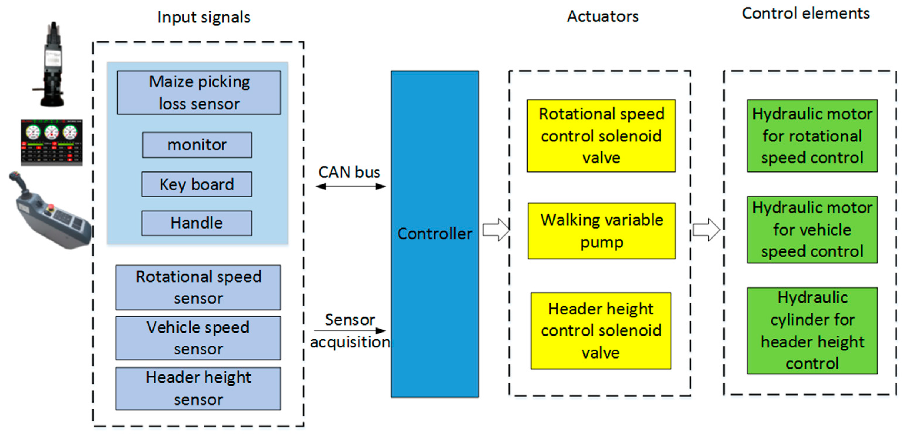
2.1.1. System Design

A schematic diagram of the intelligent control system is shown in Figure 1. A Zoomlion 4YZL-8BZ self-propelled maize combine harvester was equipped with sensors and an intelligent controller to optimize the settings automatically. The actuators of the harvester were converted from mechanical to hydraulic. The intelligent control system for maize picking includes walking control, steering control, manual control for traditional operation (up-and-down button control of the header, main clutch switch, bridge clutch switch, and unloading clutch switch), and automatic control. The system can be operated in manual or automatic control mode. The automatic control includes joint regulation of the rotational speed of the pulling rollers, operating speed, and header height.
Two cylinders are used to adjust the header height; their motion is controlled by a proportional valve. The prototype is driven by the front wheel. The driving motor is connected with the main reducer. The variable pump controls the driving motor according to the current signal sent by the controller to realize walking control of the maize harvester. The header has two hydraulic motors; each motor drives four rows of pulling rollers. Two proportional valves control the hydraulic motors according to the electrical signals sent by the controller to control the rotational speed of the pulling rollers.

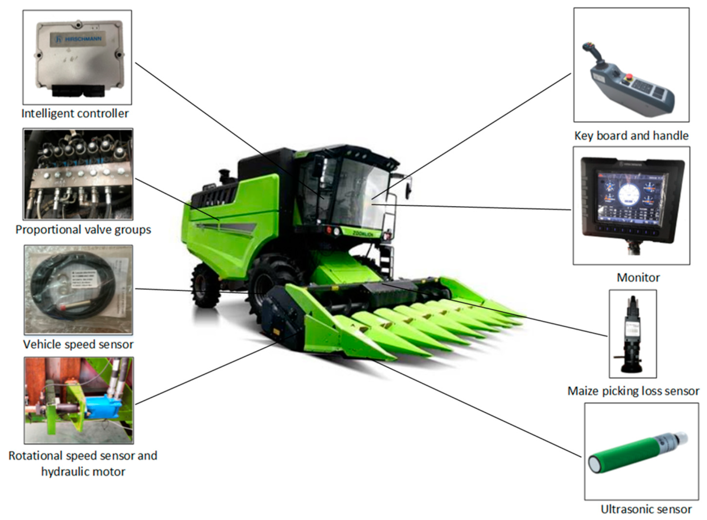
2.1.2. System Hardware Composition

Figure 2 shows a structural block diagram of the hardware components for the intelligent control system of the maize harvester. The intelligent control system comprises sensors, the intelligent controller, actuators, and hydraulic control elements. The controller was constructed with the programmable controller IMC T3654, which was specially designed for mobile machinery with a flexible input/output (I/O) port configuration and up to 90 ports. Inputs to the harvester control system include the rotational speed of the pulling rollers, operating speed, header height, maize picking loss, and button control signal (from a keyboard and handle). The maize picking loss sensor can obtain the maize picking loss rate by collecting image information of broken ears and sending it to the intelligent controller through the control area network (CAN) bus. The rotational speed sensor collects the rotational speed information of the pulling rollers. The speed sensor collects the vehicle speed information. The header height sensor detects the header height. These sensors send their information to the controller in real time. The keys and driving control handle are located on the armrest box assembly, which can send signals by the CAN bus to the controller according to the inputs of the operator in manual control mode. The sensor signals are processed by the controller, which then outputs the appropriate command signal to the actuators to adjust the cylinders or motors.

2.2. Software Algorithm

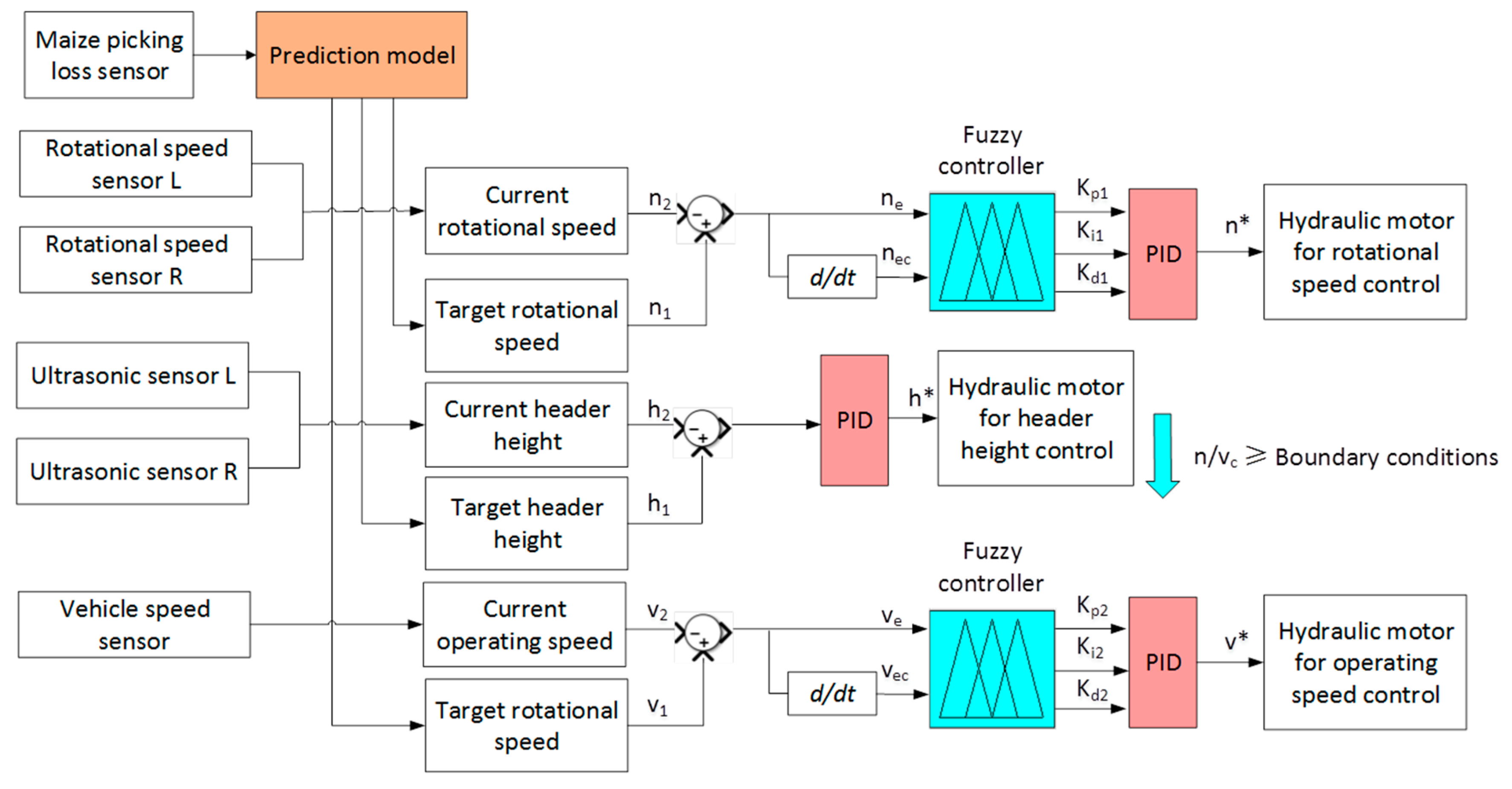
2.2.1. Control Strategy

The control system software is divided into modules: for initialization, signal input and output, acquisition and processing of the sensor signals, CAN signal sending and receiving, and logic control. The logic control includes manual and automatic control modes. Figure 3 shows the software structure diagram. After the control system is initiated, the operator can set the driving mode (parking, road, or operation) and harvest mode (manual control or automatic control). In the road and operation modes, the operator can manually adjust the header height, driving speed, and rotational speed of the pulling rollers through the corresponding keys. When the operation mode is set to automatic, the system adjusts the maize picking loss adaptively. The control system exits automatic control and returns to manual control if any manual control key is touched during the automatic harvesting process.
The control mode has two main control loops, namely, faster and slower loops. Previous research and experimental results have shown that the rotational speed of the pulling rollers has the most significant effect on the maize picking loss [21,22]. Thus, the rotational speed of the pulling rollers should be adjusted in real time depending on the maize picking loss rate, and the operating speed should match the rotational speed of the pulling rollers [23]. The faster loop regulates the rotational speed of the pulling rollers and the operating speed, and the slower loop regulates the header height. When the maize picking loss rate (MPL) exceeds the target range (0, MPLopt + ∆MPL), the faster loop adjusts the pulling rollers and operating speed. If MPL still exceeds the target range, the slower control loop fine-tunes the header height to optimize the maize picking loss rate. The values of the input parameters for both loops are determined by the prediction model and experimental data.
Figure 4 shows a block diagram of the intelligent control system for maize picking. If the maize picking loss rate exceeds the target range, the controller first calculates the target values (rotational speed of the pulling rollers n1, operating speed v1, and header height h1) as derived from the data-based prediction model. Then, the current values (n2, v2, and h2, respectively) are collected by the sensors in real time. The difference between n1 and n2 (i.e., n e ) and the deviation change rate (i.e., n e c ) are used as the input to the fuzzy PID controller for the rotational speed of the pulling rollers. The difference between v1 and v2 (i.e., ve) and the deviation change rate (i.e., v e c ) are used as the input to the fuzzy PID controller for the operating speed. The difference between h1 and h2 (i.e., he) is used as the input to the PID controller for the header height. The above three controllers are used to optimize the working parameters and maintain the maize picking loss rate within the target range to meet harvest requirements.

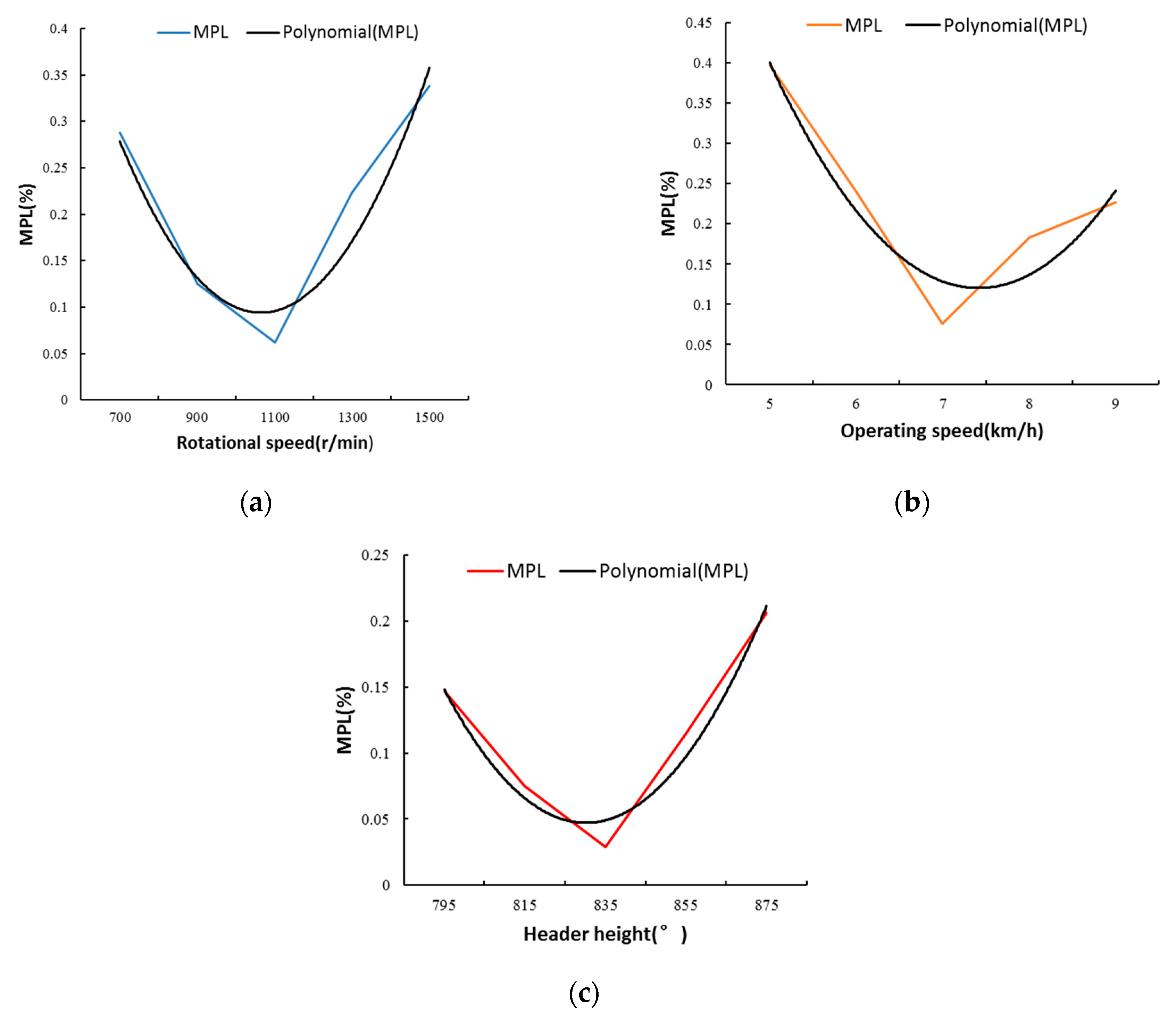
2.2.2. Data-Based Prediction Model

Preceding studies used experimental data-based models to gather considerable knowledge about the working principles of the maize picking process. The main influencing factors of the maize picking process are the rotational speed of the pulling rollers, operating speed, header height, clearance between the picking plates, crop characteristics, structural characteristics, and material properties of the maize picking components. Several scholars have obtained the influence degree and law of each factor through bench tests or field tests [24,25,26]. For plate-type mechanisms, the collision speed between the ears and picking plates directly affects the maize picking loss [27]. Thus, the most important factor that affects the maize picking process with plates is the rotational speed of the pulling rollers. Regulating the rotational speed of the pulling rollers is particularly important for the harvesting process. Second, the operating speed should match the rotational speed of the pulling rollers to ensure a proper feed rate. The header height determines not only the falling height of the ears before they collide with the picking plates but also the angle of the collision. Thus, the header height should also be adjusted. When the same variety of maize is grown in a given plot, the clearance between the picking plates is fixed and thus should not be adjusted during the harvesting process. In the present study, a data-based model was used to predict the maize picking loss rate, and the rotational speed of the pulling rollers, operating speed, and header height were optimized to minimize the maize picking loss.
Experiments verified that the rotational speed of the pulling rollers and operating speed have the following relationship with maize picking loss rate. Figure 5a shows that the maize picking loss rate is relatively low when the rotational speed of the pulling rollers is within 900–1180 r/min. Figure 5b shows that the maize picking loss rate is relatively low when the operating speed is within 6–8 km/h. Figure 5c shows that the maize picking loss rate is relatively low when the header height is within 795–835 mm, except for low cutting mode. When the operating speed and rotational speed of the pulling rollers satisfy Equations (1)–(3), the maize picking loss rate is minimized [8]:
k = v p v c sin θ = [ 0.7 ,   1 ]
n v c 60 × 1000 i z 1 p cos θ
n v c L h π d S · ( cos θ ) 2
The model of maize picking loss rate was established by a central composite design (CCD) experiment, and according to the analysis of the variance of the maize picking loss rate, the rotational speed of the pulling rollers, the header height, the interaction of the rotational speed of the pulling rollers and the header height, the interaction of the operating speed and the header height have a significant effect on the maize picking loss rate. The prediction model for the maize picking loss rate is as follows:
M P L o p t = 77.49253 0.070253 n 4.60942 h + 1.52849 × 10 3 n h + 0.74036 v c h + 1.94932 × 10 5 n 2 + 0.061976 h 2
where k is the scale factor, v p is the linear velocity of the pulling rollers ( m / s ), v c is the operating speed ( m / s ), θ is the header inclination ( ° ), and n is the rotational speed of the pulling rollers ( r / min ). The transmission ratio between the speeds of the conveying chain and pulling rollers in the header gear box is   i , where   z 1 is the number of sprocket teeth of the conveying chain driving wheel, p is the pitch ( mm ), L is the height of the maize in mm, d is the diameter of the pulling roller ( mm ), S is the length of the pulling roller ( mm ), and h is the header height ( mm ).

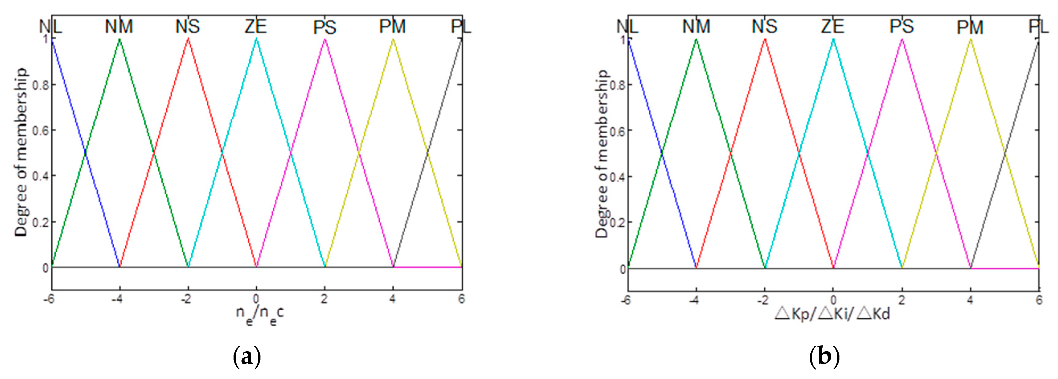
2.2.3. Design of the Fuzzy PID Controller

Fuzzy control is a time-varying control system [28] that has been successfully applied in several different disciplines, such as agriculture [29,30,31]. In the maize picking process, the rotational speed of the pulling rollers and the operating speed are time-variant; thus, fuzzy PID control is appropriate.
The fuzzy PID control system for the rotational speed mainly includes a fuzzy controller and PID controller. The difference between the target and current values for the rotational speed of the pulling rollers (i.e., n e = n 1 n 2 ) was taken as one input for the fuzzy inference unit. The deviation change rate n e c was taken as another input. The proportional coefficient K p , integral coefficient K i , and differential coefficient K d represent adjustments to the PID controller. The changes to these parameters (i.e., Δ K p , Δ K i , and Δ K d ) were selected as the outputs. The final coefficients of the proportional, integral, and derivative terms of the PID controller were K p = K p 0 + Δ K p , K i = K i 0 + Δ K i , K d = K d 0 + Δ K d . Where K p 0 , K i 0 and K d 0 denote the preset initial values of the ordinary PID controller parameters.
According to expert experience and test data, it can be known that the rotational speed of pulling rollers varies in the range of [0, 1500] r / min , and the deviation of the normal working speed is within 50 r/min. When the rotational speed decline rate exceeds 30 (r/min)/s, it is considered that the pulling rollers have a tendency to block. Therefore, the basic domain of the rotational speed deviation is [−50, 50] r/min, and the lower limit of the rotational speed deviation change rate is set to −30 (r/min)/s, and its basic domain is [−30, 30] (r/min)/s. The output of the fuzzy control system is the correction value of the PID adjustment parameters, including Δ K p , Δ K i , and Δ K d . The basic domain of Δ K p is [−0.9, 0.9]. The basic domain of Δ K i is [−0.015, 0.015]. The basic domain of Δ K d   is [−0.9, 0.9]. In order to ensure control accuracy, the basic domains of deviation, deviation change rate and the output variables (Δ K p , Δ K i , and Δ K d ) are divided into 7 grades, and the quantization domains are all {−6, −4, −2, 0, 2, 4, 6}, the corresponding fuzzy language variable set is {negative large, negative medium, negative small, zero, positive small, positive medium, positive large}, denoted as {NL, NM, NS, ZE, PS, PM, PL}. The commonly used triangular membership function was selected as the membership function. The membership functions of input n e , n e c and output Δ K p , Δ K i , and Δ K d are shown in the Figure 6.
The investigation results combined with expert opinions were input into the fuzzy inference system to form a fuzzy rule base. Table 1 presents the overall form of the fuzzy rule base. For two-dimensional fuzzy controllers, Mamdani control rules are often used. The tuning requirements of Δ K p , Δ K i , and Δ K d under different deviations n e and deviation change rate n e c are as follows:
(a)
When the deviation is small, K p and K i should be increased to make the system have better steady-state performance. Considering the anti-interference ability of the system and in order to avoid the output response from oscillating near the set value, K d should be selected appropriately. When the deviation change rate is large, K d should be smaller; on the contrary, K d should be larger.
(b)
When the deviation and the deviation change rate are medium, the value of K p should be smaller, and the value of K i should be appropriate.
(c)
When the deviation is large, in order to prevent the deviation from becoming large instantaneously and causing the differential saturation, take the larger K p and the smaller K d . The value of K i should be small to avoid integral saturation and large overshoot in the system response. For example, according to Table 1, if the rotational speed of the pulling rollers deviation is NL and the deviation change rate is NL, it means that the actual rotational speed is far below the target rotational speed and the deviation tends to increase. Therefore, K p is PL, K i is PS, and K d should choose NL. If the rotational speed deviation is ZE and the deviation rate of change is ZE, it means that the actual rotational speed is close to the target rotational speed, but the system has a static error. Therefore, K p is ZE, K i is NS, and K d is ZE. The center of gravity method was used for defuzzification to convert the output variable into a numerical value.
Similarly, the operating speed controller receives the target speed from the main controller and the actual speed from the vehicle speed sensor. It then calculates the deviation v e between the target and actual operating speed and the deviation change rate v e c . This controller also applies the proportional, integral, and differential coefficients adjusted by fuzzy control as the control inputs to regulate the operating speed error to approach 0.

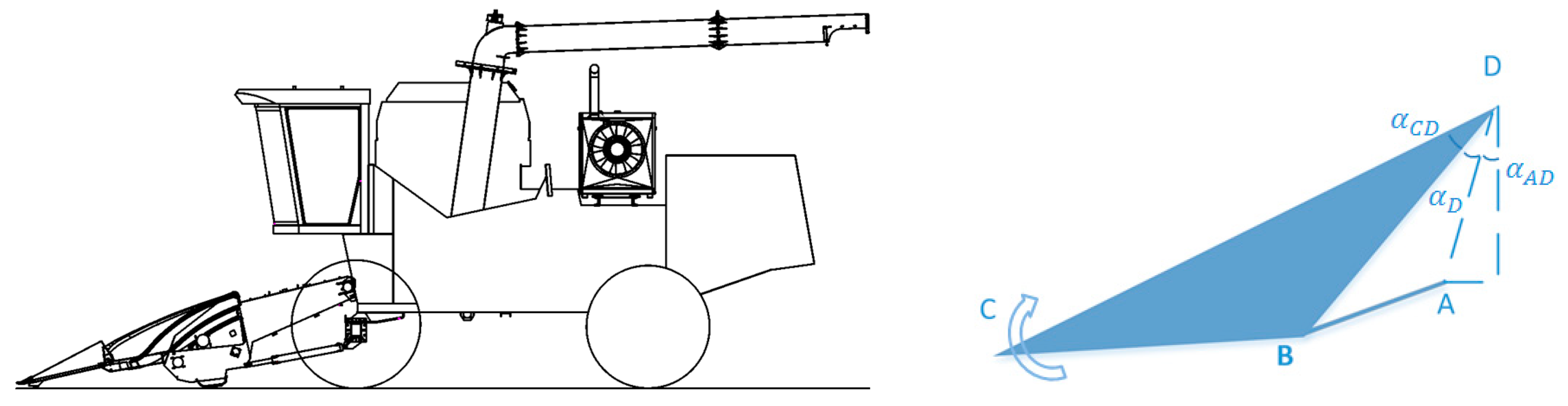
2.2.4. Header Height Control

When the piston of the header lifting the hydraulic cylinder is in different positions, the relative positions of the header components change, and the height and inclination angle of the pulling rollers also change. During the maize picking process, the piston action of the hydraulic cylinder on the header changes the height and angle of the maize picking, which affects the harvesting process. The movements of the header and bridge part were analyzed to elucidate the relationship between the height and inclination angle of the pulling rollers during the maize picking process.
Figure 7 shows the movement analysis diagram for the header. The header and bridge are simplified as the quadrilateral ABCD. As the hydraulic cylinder piston extends or retracts, the angle α D changes. The geometric relations in the graph can be used to obtain the header height h .
For the triangle ABD,
α D = a r c cos l A D 2 + l B D 2 ( l A B + y L ) 2 2 · l A D · l B D
h = h D l CD cos ( α D + α A D + α C D )
where y L is the piston displacement of the hydraulic cylinder, h is the header height (i.e., the vertical distance between point C and the ground), and h D is the vertical distance from the bridge hinge point (i.e., distance from point D to the ground).
A PID controller is a control loop feedback mechanism commonly used in various control systems [32,33]. This is a simple and highly reliable algorithm, and it can reduce the response time. A PID controller was applied to minimize the error in the header height and improve the dynamic response of the hydraulic system as well as the resulting maize picking quality. The header height controller receives the target height from the intelligent controller and the actual height from the ultrasonic sensors. It then calculates the deviation h e between the target and actual header heights. A linear combination of the proportional error, integral error, and differential error is applied as the control inputs to adjust the height error to approach 0.

3. Experimental Testing and Analysis of the Developed System
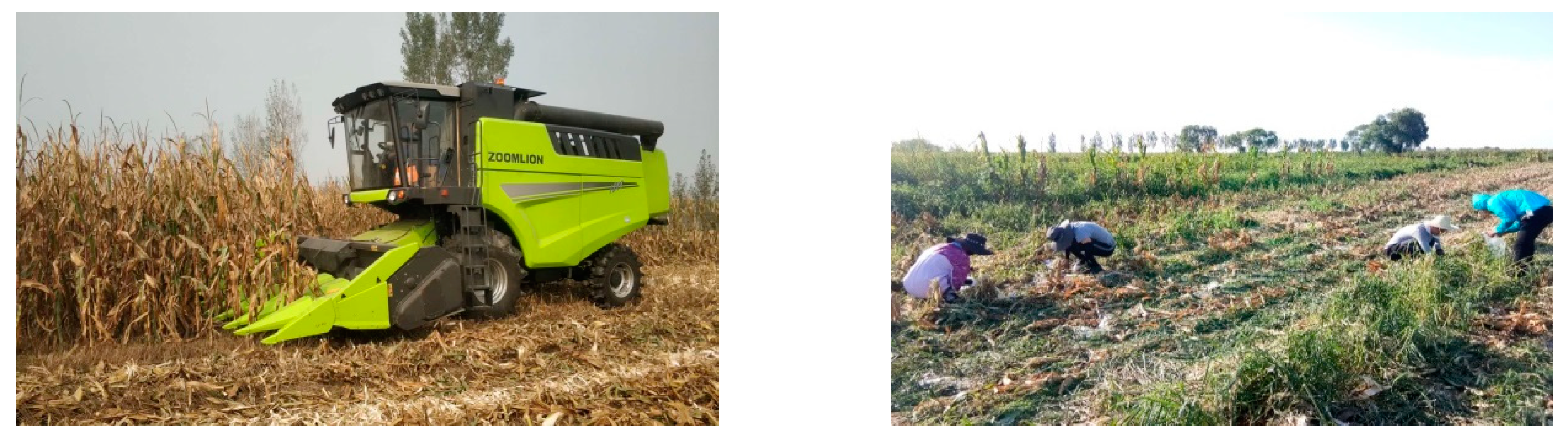
3.1. Materials

Field experiments were conducted at Zhoukou, Henan Province, on 18 September 2020, to evaluate the maize picking performance with the intelligent control system. The proposed intelligent control system was tested on a Zoomlion 4YZL-8BZ maize combine harvester. Table 2 presents the relevant parameters of the machine. The intelligent control system was programmed in CODESYS V3.5. Two ultrasonic sensors (type UKF1600-G18-VN7L-Q12) were used with a maximum detection distance of 1600 mm and a repeatability accuracy of 5%. The speed sensors at the header were coaxial with the hydraulic motors of the pulling rollers, and the vehicle speed sensor was fixed on the main reducer housing. The stroke of the hydraulic cylinder lifting the header was 500 mm, and the cylinder diameter was 60 mm. Thus, the header height could be adjusted from 50 to 1180 mm. The displacement of the driving motor at the pulling rollers was 161.1 mL/r, so the rotational speed of the pulling rollers could be adjusted in the range of 0–1500 r/min. The displacement of the piston pump was 100 mL/r, and the driving speed of the maize harvester could reach 0–10 km/h in first gear and 10–25 km/h in second gear.

3.2. Experimental Tests and Results

The field experiments were conducted according to the methods specified in GB/T 21961-2008 for maize harvesting machinery. Before the experiments, the moisture content of the maize kernels was determined to be 28–30%. Figure 8 shows the harvesting process. The test area was divided into a stable area of 20 m long, a measurement area of 20 m long, and a parking area of 15 m long. All dropped ears were removed from the measurement area before harvest. After harvest, fallen kernels (including the kernels in the straw), the broken ears, and newly dropped ears (including ears more than 5 cm long) in the same area were collected and weighed to measure the maize picking loss. The maize picking loss rate M P L (%) was calculated as follows:
M P L = W L W Z × 100
where W Z is the total kernel weight (g) and W L is the weight of seeds on the ground (g).

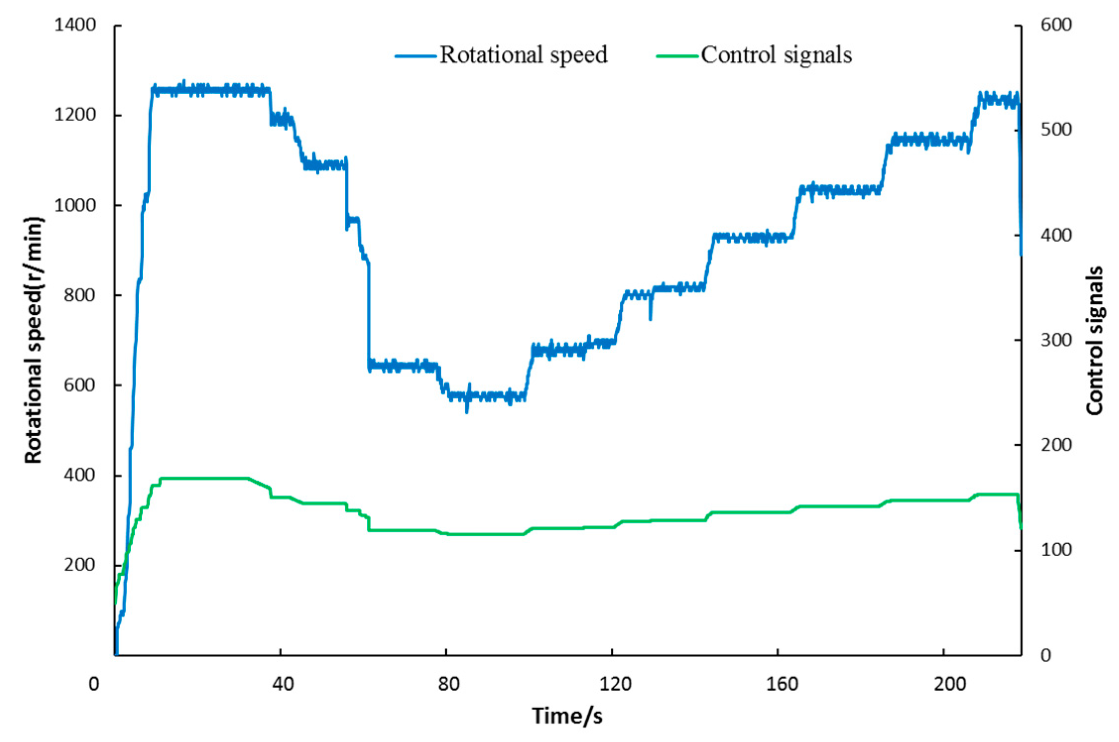
3.2.1. Adjustment Test of Working Parts

The adjustment of the working parts included the rotational speed control of the pulling rollers, operating speed control, and header height control. The rotational speed of the pulling rollers was regulated most strictly. When there was no load (i.e., no maize was harvested), the control strategy was tested to verify that the rotational speed of the pulling rollers could be automatically adjusted. First, the rotational speed of the pulling rollers was adjusted to a certain value (slightly higher than the usual working range) through manual button control before a harvest. Then, a maize picking loss rate which is higher or lower than the standard value (the standard loss rate in China is <4%) was input by manual to the controller, and it is observed whether the rotational speed would change according to the designed strategy. Figure 9 shows the corresponding changes in the control signal and rotational speed of the pulling rollers. The rotational speed of the pulling rollers was manually adjusted to approximately 1260 r/min. After approximately 35 s, the input of a high maize picking loss rate caused the controller to send a flow reduction control command to the proportional valves, and the rotational speed of the pulling rollers began to decrease by approximately 50 r/min every 15 s until the lower limit for the optimal rotational speed was reached. At approximately 80 s, a low maize picking loss rate was input, and the controller issued a flow increase control command to the proportional valves while ensuring that the loss rate did not exceed the allowable range. The rotational speed of the pulling rollers was gradually increased to improve the harvesting efficiency. The header took 12 s to rise from 0 to 1100 mm, and it took 11 s to descend from the maximum height to the minimum. The operating speed could be adjusted from 0 to 25 km/h according to the position of the analog handle from 0 to 1000.

3.2.2. Field Experiment of System

Before a harvest, the operator first adjusts the working parameters to empirical values based on personal experience. The initial rotational speed of the pulling rollers was set to approximately 1200 r/min, the header height was set to 500 mm in low cutting mode, and the harvesting was conducted at an operating speed of 7 km/h. Figure 10a shows the regulation process of the corresponding outputs when the maize picking loss rate was high, and the two red circles respectively indicate the first and second deceleration of the rotational speed of the pulling rollers. The ears of maize were harvested after approximately 5 s. At the beginning of the harvest, the excessively high rotational speed of the pulling rollers and operating speed caused the ears to bounce higher. The greater impact force caused more ears to be broken, and the maize plants were jammed on the header. The maize picking loss sensor shows a larger equivalent value for the maize picking loss, which means that the maize picking loss rate was high. At this time, the controller sent a flow reduction control command to the proportional valves to decrease the rotational speed of the pulling rollers according to the received maize picking loss rate and formulated control strategy. The rotational speed of the pulling rollers was adjusted twice and was reduced to approximately 1100 r/min. The operating speed was reduced from approximately 7 to 6 km/h. This significantly reduced the popping height of the ears, and the header was no longer congested. Thus, the maize picking loss rate was reduced to the allowable range. In order to calibrate the maize picking loss sensor and verify the validity of the intelligent control system, the maize picking loss rate was determined manually through statistics after the maize was harvested. The manually measured maize picking loss rate was 1.676%, and the acceptable loss rate in China is <4% (ear harvesting), which satisfies maize harvesting requirements.
Before the second experiment, the initial rotational speed of the pulling rollers was set to approximately 900 r/min, and the header height was set at 500 mm. The maize was picked at an operating speed of 5 km/h. Figure 10b shows the regulation process of the corresponding outputs, and the two red circles respectively indicate the first and second increase in the rotational speed of the pulling rollers. In the early stages of the harvest, the slow feeding of maize plants at the header was caused by the low rotational speed of the pulling rollers and the low operating speed. Although the maize picking loss rate was within the allowable range, the maize harvest efficiency was low. Thus, the controller issued a flow increase control command to proportional valves to increase the rotational speed of the pulling rollers. The rotational speed of pulling rollers was adjusted to approximately 1050 r/min, and the operating speed was increased to 6 km/h. During this time, the maize picking loss rate did not exceed the allowable range, and the harvest efficiency improved. After the maize was harvested, the maize picking loss rate was determined manually through statistics. The manually measured maize picking loss rate was 1.386%, which satisfies maize harvesting requirements.

4. Conclusions

In this study, an intelligent control system based on a prediction model was designed to control the picking performance of maize harvester. The prediction model which established by a CCD experiment was used to optimize the tradeoff between the acceptable maize picking loss and influence factors to minimize grain losses. The control system can realize manual or automatic controls, and the controller adjusts the rotational speed of pulling rollers, the operating speed, and header height based on the measured picking losses in automatic mode. The designed automatic control system comprises faster and slower loops, and the double closed-loop control algorithm based on fuzzy control and PID control in the present study is simple yet effective, and it can be used to control all output signals to regulate the rotational speed of the pulling rollers, operating speed, and header height toward target values. The system test results showed that all working parts responded quickly to changes in inputs, and the overshoot and steady-state errors were relatively small. Under load and no-load test conditions, the maize harvester could use the established control strategy to optimize each working parameter. The test results showed that the maize picking loss rate was 1.676% in the first field experiment with a higher rotational speed of pulling rollers and 1.386% in the second field experiment with a lower rotational speed. These values meet harvesting requirements. This study can provide a reference for future research on the automatic control of maize harvesters.

Author Contributions

Conceptualization, Z.Z.; data curation, Z.Z., N.D. and X.L.; methodology, Z.Z.; validation, Z.Z. and N.D.; investigation, Z.Z. and R.C.; resources, R.C., Y.D. and B.X.; writing—original draft preparation, Z.Z.; writing—review and editing, Z.Z.; supervision, R.C., Y.D. and B.X.; project administration, R.C. and Y.D.; funding acquisition, R.C. and Y.D. All authors have read and agreed to the published version of the manuscript.

Funding

This research was funded by the National Key R&D Program Projects (2016YFD0701901).

Acknowledgments

The authors are grateful for the College of Engineering, China Agriculture University for the laboratory support to conduct this research.

Conflicts of Interest

The authors declare no conflict of interest.

References

  1. Craessaerts, G.; Baerdemaeker, J.D.; Missotten, B.; Saeys, W. Fuzzy control of the cleaning process on a combine harvester. Biosyst. Eng. 2010, 106, 103–111. [Google Scholar] [CrossRef]
  2. Craessaerts, G.; Baerdemaeker, J.D.; Saeys, W. Fault diagnostic systems for agricultural machinery. Biosyst. Eng. 2010, 106, 26–36. [Google Scholar] [CrossRef]
  3. Li, Y.; Tao, C.; Zhe, Q.; Ke, L.; Xiao, Y.; Dan, H.; Bing, Y.; Dong, Z.; Dong, Z. Development and application of mechanized maize harvesters. Int. J. Agric. Biol. Eng. 2016, 9, 15–28. [Google Scholar] [CrossRef]
  4. Huimin, F.; Mengmeng, N.; Song, S.; Hu, L.; Jin, Z. Effect of harvesting methods and grain moisture content on maize harvesting quality. Chin. Soc. Agric. Eng. Trans. 2019, 35, 11–18. [Google Scholar] [CrossRef]
  5. Duan, G.; Dao, Z.; Q, L.; Pei, D. Experimental study on technical parameters of raking and conveying device of corn harvester. Trans. Chin. Soc. Agric. Eng. 2012, 28, 45–49. [Google Scholar] [CrossRef]
  6. Tao, C.; Jia, L.; Dong, Z.; Li, Y. Design and experiment of cob-picking and stalk-chopping united mechanism. Trans. Chin. Soc. Agric. Mach. 2012, 10, 95–100. [Google Scholar] [CrossRef]
  7. Hong, J.; Gang, W.; Jia, Z.; Chang, L.; Yu, W.; Hui, G. Design and experiment of Spacing-adaptive differential snapping rollers for corn harvester. Trans. Chin. Soc. Agric. Mach. 2015, 46, 97–102. [Google Scholar] [CrossRef]
  8. Chinese Academy of Agricultural Mechanization Sciences. Agricultural Machinery Design Manual; Machinery Industry Press: Beijing, China, 2007; Volume 2, pp. 1018–1019. [Google Scholar]
  9. Tulpule, P.; Kelkar, A. Integrated robust optimal design (IROD) of header height control system for combine harvester. In Proceedings of the American Control Conference, Portland, OR, USA, 4–6 December 2014; pp. 2699–2704. [Google Scholar] [CrossRef]
  10. Xie, Y.; Alleyne, A.; Greer, A.; Deneault, D. Header height control of a combine harvester system. In Proceedings of the ASME 2010 Dynamic Systems and Control Conference, Cambridge, MA, USA, 12–15 September 2015. [Google Scholar] [CrossRef]
  11. Xie, Y.; Alleyne, A. Two degree of freedom control synthesis with applications to agricultural systems. J. Dyn. Syst. Meas. Control 2014, 136, 051006. [Google Scholar] [CrossRef]
  12. Yong, L.; Yang, X.; Ming, W.; Da, L.; Yi, C.; Ya, L. Design and test of the adaptive height adjustment system for header of the combine-harvester. J. Hunan Agric. Univ. 2018, 44, 326–329. [Google Scholar] [CrossRef]
  13. Jin, C.; Shuqing, W.; Yi, L. Design and test of header parameter keys electric control adjusting device for rice and wheat combined harvester. Chin. Soc. Agric. Eng. Trans. 2018, 34, 19–26. [Google Scholar] [CrossRef]
  14. Jin, C.; Xiaobo, N.; Yaoming, L.; Guangjin, Y.; Pei, W. Fuzzy adaptive control system of forward speed for combine harvester based on model reference. Trans. Chin. Soc. Agric. Mach. 2014, 45, 87–91. [Google Scholar] [CrossRef]
  15. Yong, C.; Xu, Z.; Deqing, T. Design of automatic speed control system of combine reel. Agric. Mech. Res. 2018, 40, 129–133. [Google Scholar] [CrossRef]
  16. Omid, M.; Lashgari, M.; Mobli, H.; Alimardani, R.; Mohtasebi, S.; Hesamifard, R. Design of fuzzy logic control system incorporating human expert knowledge for combine harvester. Expert Syst. Appl. 2010, 37, 7080–7085. [Google Scholar] [CrossRef]
  17. Jun, N.; Han, M.; Xiu, C. Self-adjustment fuzzy control for threshing cylinder and its VLSI implementation. Chin. Soc. Agric. Eng. Trans. 2010, 26, 134–138. [Google Scholar] [CrossRef]
  18. Craessaerts, G.; Saeys, W.; Missotten, B.; Baerdemaeker, J.D. Identification of the cleaning process on combine harvesters. Part I: A fuzzy model for prediction of the material other than grain (MOG) content in the grain bin. Biosyst. Eng. 2008, 101, 42–49. [Google Scholar] [CrossRef]
  19. Craessaerts, G.; Saeys, W.; Missotten, B.; Baerdemaeker, J.D. Identification of the cleaning process on combine harvesters, Part II: A fuzzy model for prediction of the sieve losses. Biosyst. Eng. 2010, 106, 97–102. [Google Scholar] [CrossRef]
  20. Du, C.; Shu, W.; Feng, K.; Qing, Z.; Xiao, L. Mathematical model of feeding rate and processing loss for combine harvester. Chin. Soc. Agric. Eng. Trans. 2011, 27, 18–21. [Google Scholar] [CrossRef]
  21. Guo, F.; Hui, W.; Jun, J.; Wen, C.; Huan, L.; Jin, H.; De, C.; Zu, Z.; Shi, W. Analysis of influence factor on seed damage rate and loss rate during picking corn-cob. Chin. Soc. Agric. Eng. Trans. 2002, 18, 72–74. [Google Scholar]
  22. Jin, T.; Jun, H.; Zhi, C.; Xiao, L. Research and development of testing device with snapping rolls for corn harvester. Trans. Chin. Soc. Agric. Mach. 2007, 38, 48–51. [Google Scholar] [CrossRef]
  23. Jun, H.; Jin, T. Development of no-tillage technology and no-tillage planter. Chin. Soc. Agric. Eng. Trans. 2006, 29–31. [Google Scholar] [CrossRef]
  24. Qian, W.; Ke, H.; Cheng, J.; Xiu, L.; Duan, G.; Guo, Z. Mechanism analysis and experiment optimization on parameters of maize exciting and picking. Trans. Chin. Soc. Agric. Mach. 2018, 49, 249–257. [Google Scholar] [CrossRef]
  25. Ai, G.; Ru, L.; Shuang, L.; Ji, Z.; Ke, Z. Performance experiment of corn harvester header. Trans. Chin. Soc. Agric. Mach. 2013, 44, 27–31. [Google Scholar] [CrossRef]
  26. Ai, G.; Jian, Y.; Ji, Z.; Zhi, Z.; Qi, Y.; Ru, L. Influence factor analysis of mechanical damage on corn ear picking. Chin. Soc. Agric. Eng. Trans. 2016, 32, 56–62. [Google Scholar] [CrossRef]
  27. Qian, F.; Jun, F.; Zhi, C.; Lu, R. Loss reduction mechanism and experiment on snapping of rigid-flexible coupling corn head. Trans. Chin. Soc. Agric. Mach. 2020, 51, 60–68. [Google Scholar] [CrossRef]
  28. Cheng, R.; Dean, Z.; Yue, S.; Jiang, H.; Shi, D.; Ji, L. Design and testing of a control system associated with the automatic feeding boat for farming Chinese river crabs. Comput. Electron. Agric. 2018, 150, 14–25. [Google Scholar] [CrossRef]
  29. Reza, M.; Mortaza, A. Design of an interval type-2 fractional order fuzzy controller for a tractor active suspension system. Comput. Electron. Agric. 2019, 167, 1–10. [Google Scholar] [CrossRef]
  30. Berk, P.; Belšak, A.; Stajnko, D.; Lakota, M.; Muškinja, N.; Hočevar, M.; Rakun, J. Intelligent automated system based on a fuzzy logic system for plant protection product control in orchards. Int. J. Agric. Biol. Eng. 2019, 12, 92–102. [Google Scholar] [CrossRef]
  31. Yong, W.; Li, L.; Shuai, L.; Hong, W.; Man, Z.; Hong, S.; Nikolaos, S.; Minzan, L. Optimal control algorithm of fertigation system in greenhouse based on EC model. Int. J. Agric. Biol. Eng. 2019, 12, 118–125. [Google Scholar] [CrossRef] [Green Version]
  32. Park, S.H.; Im, B.U.; Park, D.K. Model based optimum PID gain design of adaptive front lighting system. Int. J. Automot. Technol. 2018, 19, 923–933. [Google Scholar] [CrossRef]
  33. Bucz, S.; Kozakova, A.; Vesely, V. Easy tuning of PID controllers for specified performance. IFAC Proc. 2012, 45, 733–738. [Google Scholar] [CrossRef]
Figure 1. Schematic diagram of intelligent control system.
Applsci 10 08888 g001
Figure 2. Structure block diagram of the hardware system.
Applsci 10 08888 g002
Figure 3. Software structure diagram.
Applsci 10 08888 g003
Figure 4. Control block diagram of intelligent control system for maize picking. n*, h*, v* are the outputs value of three controllers.
Applsci 10 08888 g004
Figure 5. Relationship between the main factors and the maize picking loss rate respectively: (a) Relationship between the rotational speed of the pulling rollers and maize picking loss rate (MPL); (b) Relationship between the operating speed and MPL; (c) Relationship between the header height and MPL.
Applsci 10 08888 g005
Figure 6. Membership functions of input and output: (a) Membership function of the input variables n e , n e c ; (b) Membership function of the output variables Δ K p , Δ K i , and Δ K d .
Applsci 10 08888 g006
Figure 7. Movement analysis diagram of header.
Applsci 10 08888 g007
Figure 8. Field experiment.
Applsci 10 08888 g008
Figure 9. Automatic adjustment of pulling rollers under no load.
Applsci 10 08888 g009
Figure 10. Automatic adjustment of pulling rollers under a load. (a) Regulation process of the corresponding outputs when the maize picking loss rate was high. (b) Regulation process of the corresponding outputs when the maize picking loss rate was in the allowable range.
Applsci 10 08888 g010
Table 1. Fuzzy rules of Δ K p , Δ K d , and   Δ K i .
n e
n e c Δ K p   Δ K d   Δ K i
NLNSZEPSPL
NLPL/NL/PSPL/NLZEPL/NL/ZEPS/NL/ZEZE/ZE/PS
NSPL/NL/NLPS/NS/NLPS/NS/NSZE/ZE/ZENL/PS/PS
ZEPS/NS/NLPS/NS/NLZE/ZE/NSNS/PS/ZENL/PS/PS
PSPS/NS/NLZE/ZE/NSNS/PS/NSNS/PS/ZENL/PL/PS
PLZE/ZE/PSNS/PS/ZENS/PS/ZENL/PL/ZENL/PL/PS
Table 2. Machine parameters.
ParameterValue
Engine speed (r/min)2200
Reduction ratio of wheel reducer Front axle final drive ratio7.727
Operation 7.295
Road 3.638
Speed ratio at header2.7
Front wheel diameter (mm)1540
Machine weight (kg)No load 10,000 Full load 12,000
Remarks: the speed ratio at header refers to the reduction ratio from the pulling rollers motor to pulling rollers.
Publisher’s Note: MDPI stays neutral with regard to jurisdictional claims in published maps and institutional affiliations.

