Article

A Hands-On Laboratory for Intelligent Control Courses

by
Hugo Torres-Salinas
1,†,
Juvenal Rodríguez-Reséndiz
2,*,†,
Adyr A. Estévez-Bén
2,3,*,†,
M. A. Cruz Pérez
4,†,
P. Y. Sevilla-Camacho
5,† and
Gerardo I. Perez-Soto
2,†
1
Facultad de Informática, Universidad Autónoma de Querétaro, Nuevo Juriquilla, Juriquilla, Querétaro 76230, Mexico
2
Facultad de Ingeniería, Universidad Autónoma de Querétaro, Cerro de las Campanas, Las Campanas, Querétaro 76010, Mexico
3
Facultad de Química, Universidad Autónoma de Querétaro, Cerro de las Campanas, Las Campanas, Querétaro 76010, Mexico
4
División de Posgrado, Universidad del Valle de México, Querétaro 76230, Mexico
5
Ingeniería Mecatrónica, Universidad Politecnica de Chiapas: Suchiapa, Chiapas 29150, Mexico
*
Authors to whom correspondence should be addressed.
These authors contributed equally to this work.
Appl. Sci. 2020, 10(24), 9070; https://doi.org/10.3390/app10249070
Submission received: 30 November 2020 / Revised: 11 December 2020 / Accepted: 14 December 2020 / Published: 18 December 2020
(This article belongs to the Special Issue Advances in Artificial Intelligence Learning Technologies)

Abstract

:
This research focused on developing a methodology that facilitates the learning of control engineering students, specifically developing skills to design a complete control loop using fuzzy logic. The plant for this control loop is a direct current motor, one of the most common actuators used by educational and professional engineers. The research was carried out on a platform developed by a group of students. Although the learning techniques for the design and implementation of controllers are extensive, there has been a delay in teaching techniques that are relatively new compared to conventional control techniques. Then, the hands-on laboratory offers a tool for students to acquire the necessary skills in driver tuning. In addition to the study of complete systems, the ability to work in a team is developed, a fundamental skill in the professional industrial area. A qualitative and quantitative analysis of student learning was carried out, integrating a multidisciplinary project based on modern tools.

1. Introduction

Nowadays, it is necessary for teachers to continue updating their class methodology, even when there are already established models of education, adapting to new tools that facilitate student learning [1,2,3]. More often, teachers utilize new technology-based instruments as a learning practice. In the engineering area, teachers must ensure that students develop problem-solving skills in various topics, including industrial processes, the design of methodologies, design and construction of houses and reduction of energy expenditure, to name a few. The transmission of content in the fields mentioned above uses the handling of a wide variety of technical instruments [4] to build knowledge. Teaching must consider epistemic practices [5] and train students in both practical and ethical awareness [6,7,8], in addition to seeking that the cultural and racial aspects of the student are not a limitation in the quality of education they receive [9].
The automation area requires knowledge in topics such as electrical systems, digital electronics, power electronics, microcontrollers, mathematical modeling, communication protocols and, an area that is especially difficult for the student, control theory [10,11]. Control theory requires a high load of mathematical analysis. In this regard, different studies show that the academic performance of students improves when they participate in practical activities related to science and technology [12]. Other studies have concluded that mathematics is one of the main subjects that define the success of obtaining a bachelor degree in exact science careers [13,14,15]. In the teaching of subjects that contain a high load of mathematics, improv ing student performance continues to represent one of the main challenges [16,17].
Engineering schools extensively address conventional control systems. The Proportional-Integral- Derivative (PID) is one of the most implemented controllers today, since the classic control continues to be the most widely used method to achieve the desired values in the variables of industrial processes. Conventional control has access to a wide variety of commercial instruments that facilitate its implementation. However, this technique has the limitation that its implementation is relatively simple only in Single-Input–Single-Output (SISO) systems, since in Multiple-Input–Multiple-Output (MIMO) systems the adjustment of the gains is complicated [18]. It is necessary to create a new control loop if more than one variable is required to be regulated. In addition, the processes to be controlled must present a linear behavior, which is why they are inefficient for non-linear systems [19,20,21].
The main advantage of the application of fuzzy logic is the possibility of defining and including concepts or variables in an analysis, even when they are not precisely formulated. Although at present fuzzy logic has gained ground in the area of automatic control, there are still some limitations that must be resolved. Future work should be aimed at optimizing the learning time of the method, improving the interpretation of fuzzy values and developing a rigorous mathematical analysis that guarantees that the use of a fuzzy expert system results in a stable system. Therefore, the aforementioned aspects constitute possible points of improvement in the area.
Currently, different tools have been developed to help engineering students improving in the necessary skills to practice their profession without limitations of theoretical and practical knowledge in the future. There is a wide collection of works that specialize in remote work and distance education [22,23,24,25,26], such as simulations [27,28,29,30] and virtual reality [31,32]. Recent research proposes new tools for learning. Franzoni et al. [33] proposed an innovative visual tool for continuous analysis of students in real time. Particularly, in the Faculty of Engineering, Universidad Autónoma de Querétaro research has been carried out denoting the advantages it has for students to implement educational strategies that include theoretical and practical knowledge [34,35]. It is necessary that new engineers know different ways of carrying out the control to obtain the desired values in the system without the limitation of knowing and handling only conventional techniques that generate disadvantages compared to what other specialists who are capable of designing these new strategies have.
Table 1 displays the most relevant works related to the theme developed. It is important to note that there is a trend in the development of simulation-based skills. However, it is important to develop practical skills in students to consolidate their theoretical training in a context where the importance and the values given to the solution are assumed in the methodology and in the team way to work. This is to be cultural knowledgeable and to learn from the group by interactions. Furthermore, the review of related works exhibits that there are three fundamental ideas in the field of engineering education:
  • The first is a geographical shift from high-income western countries to the strong emerging economies of Asia and Latin America.
  • The second trend is a movement towards open curricula adapted to social needs.
  • The third trend is the motivation to deliver an integrated student-centered learning experience on a large scale.
This work focuses on the complete development of a control loop based on fuzzy logic, which seeks to solve two important problems. The first offers the student a different control technique from those widely studied at the undergraduate level, which translates into a first approach to fuzzy controllers. The second is that it offers a metric that allows evaluating whether the student has the skills required to perform in the professional field, where there are lots of different points of view or approaches to learning. Even though there are many jobs where teaching methods and tools are employed for fuzzy logic [36,37,38,39], the main contribution of the work represented in this document is that it proposes a specific tool and the method to evaluate the student according to the requirements requested by the Accreditation Board for Engineering and Technology (ABET). This voluntary accreditation is the product of the collaboration of more than 2000 professionals from 36 partner organizations. In addition, it has a high level of demand since its primary objective is to ensure that the engineering and science curricula comply with the global quality standards of the professions to which they are directed.
This paper consists in using the skills and knowledge of the students to develop a control loop. The student must obtain the requirements to handle multiple disciplines such as control, programming, fuzzy logic and electronics. Then, it is necessary to build the loop of the motor components of a power stage that works with Pulse Width Modulation (PWM), and finally a fuzzy controller. The structure of the work is as follows. Section 3 presents the general description of the project and the methodology developed. In Section 4, the practical sequence to be followed by the students is described, which includes the construction of the card for the acquisition of the data.

2. Fuzzy Logic Background

One of the first works that adopted this type of controller and which many consider being the pioneer in this subject was presented by Zadeh in 1965 [40]. Since this work, more than 50 years have passed, and, during this period, numerous papers have been published with related themes, the field has experienced enormous growth and many of Zadeh’s seminal concepts have naturally evolved in different directions. This technique has been utilized to identify the plant to be controlled as well as to identify patterns that help improving the performance of systems in general. In 1995, Li-Xin Wang [41] proved that fuzzy systems can be used as identifiers for nonlinear dynamic systems. In this workm the author demonstrated the following points:
  • Fuzzy identifiers are easy to implement.
  • Multiple input and output variables can be added in MIMO systems.
  • It has lower computational cost than other artificial intelligence techniques.
  • It delivers quick responses in most control processes.
The behavior of the system and the tuning of the parameters can be done without the need for an exact mathematical model and merely knowing the full functioning [42]. The two most widely implemented types of fuzzy inference systems are the so-called Mamdani [43] and Takagi–Sugeno–Kang (TSK) [44] methods. In this paper, the Mamdani method is selected, which can best be expressed as a control that employs a natural language that works with expressions, rather than numbers, or sentences instead of equations. However, process variables are not measured in common sense, but in numbers. Therefore, it is necessary to make a prior adaptation before entering the state of the variable to the controller; this stage is called fuzzification [45]. Then, the fuzzy controller, according to a rule base, performs an action that is also a form of linguistic expression that finally becomes a number again in the defuzzification stage [46].
The important concepts to understand the process of converting a conventional method to one that uses the techniques previously described are the following:
  • The universe of discourse is defined as the set X of all the possible values that a given variable x can take.
  • A fuzzy set is a set that can partially contain elements, that is, the property that an element x belongs to the set A ( x A ) can be true with a partial degree of truth.
  • A crisp set is the conventional set and only considers whether or not an element belongs to it, which means that it is a binary set.
  • Let A be a fuzzy set and let ( x X ) be a value of the universal set; the membership function described in Equation (1) indicates the degree of belonging of said value to a fuzzy set.
    μ A ( x ) : X [ 0 , 1 ]
Therefore, fuzzy set A is defined as Equation (2).
A = ( x , μ A ( x ) ) : x X , μ A ( x ) : X [ 0 , 1 ]

2.1. Operations with Fuzzy Sets

Certain operations can be performed between this type of set. The main ones are equality, inclusion, union, intersection and complement. These operations work in a similar way to operations on classic sets. The equality operation described in Equation (3) states that two fuzzy sets A and B, defined in the same universe X, are equal if they have the same membership function. Inclusion states that, given two fuzzy sets A and B, A is a subset of B ( A B ) if its membership function takes smaller values. This is described in Equation (4).
μ A ( x ) = μ B ( x ) x X
μ A ( x ) μ B ( x ) x X
If there is a value x X such that μ A ( x ) μ B ( x ) , then it is defined as ( A B ) .
For the union operation, the generalized form is taken, which is a triangular conorm, the well known T-conorm (⊥), and can be expressed according to Equation (5).
μ A B ( x ) = ( μ A ( x ) , μ B ( x ) )
A T-conorm must satisfy the following properties a , b , c , d [ 0 , 1 ] :
  • Commutativity: ( a , b ) = ( b , a ) .
  • Monotonicity: ( a , b ) < ( c , d ) if a c and b d .
  • Identity element: ( a , 0 ) = a .
  • Associativity: ( a , ( b , c ) = ( ( a , b ) , c .
The T-conorm that corresponds to fuzzy sets is the maximum, therefore Equation (5) is rewritten to obtain Equation (6).
μ A B ( x ) = m a x ( μ A ( x ) , μ B ( x ) )
For the intersection operation described in Equation (7), the triangular norm is needed, also called T-norm(T).
μ A B ( x ) = T ( μ A ( x ) , μ B ( x ) )
For the T-norm, the conditions that must be met a , b , c , d [ 0 , 1 ] are the following:
  • Commutativity: T ( a , b ) = T ( b , a ) .
  • Monotonicity: T ( a , b ) < T ( c , d ) if a c and b d .
  • Identity element: T ( a , 0 ) = a .
  • Associativity: T ( a , T ( b , c ) = T ( T ( a , b ) , c .
The T-norm that corresponds to fuzzy sets is the minimum. Equation (8) is obtained once this t-norm is substituted in Equation (7).
μ A B ( x ) = m i n ( μ A ( x ) , μ B ( x ) )
For the complement operation ( μ A ¯ ), the following axioms have to be satisfied.
  • μ A ¯ is a continuous function.
  • Monotonicity: If a b , then μ A ¯ μ B ¯ .
  • Involution: μ μ A ¯ ¯ = A
The complement can be defined as in the classical sets described in Equation (9).
μ A ¯ = 1 μ A ( x )

2.2. Fuzzification

The fuzzification stage transforms a number to a previously defined linguistic expression. Each number in this stage maps to membership functions described in this stage, which gives a degree of membership to one or more of the membership functions that can be triangular, trapezoidal or Gaussian in shape, depending the selection on the user. The degree of membership is in the range of 0 to 1, and the number can map into more than one function having different ranges with different degrees each one.

2.3. Rules

Once the membership functions have been defined for the fuzzification stage, the inference engine determines the action to be taken depending on the degrees of membership for each input variable after they have been transformed from numbers to expressions. As mentioned, these rules are of the IF-THEN type, for example, if input variable 1 is low, then output 1 is low; when there is more than one input variable, the logical disjunction connectors (OR) or conjunction (AND) are used; and if input variable 1 is low and input variable 2 is high, then output 1 is medium. At this point, the output or the corresponding action is a linguistic expression and not a number. Then, membership functions for the output functions are defined too.

2.4. Defuzzification

Since the output of the inference engine is still a linguistic expression, it is necessary to convert it again to a number. Thus, the defuzzification process is carried out, allowing a numerical value to be associated with a fuzzy set performed to calculate the output value of diffuse systems. The fuzzy inference engine concludes the input information but is expressed in fuzzy variables. This fuzzy conclusion or output is obtained by the fuzzy inference stage, but the system output data must be a real number and must be representative of the whole set, which is why there are different defuzzification methods. For this project, the centroid method is utilized, which is one of the preferred methods to implement. This process, therefore, performs the reverse procedure to the fuzzification stage.

3. Project Description and Methodology

The control loop is presented in Figure 1, which consists of the Direct Current (DC) motor, the power stage, the encoder and the Data Acquisition (DAQ) card. Furthermore, the control strategy to obtain the control requirements is fuzzy logic.
θ * ( s ) is the reference of the angular position of the motor shaft, E ( s ) is the error, U c ( s ) is the control signal sent to the DAQ, U P W M ( s ) is the PWM signal in the form of voltage that is sent to the power stage, U M ( s ) is the motor activation signal and θ ( s ) is the current position of the motor shaft.
The data acquisition card is the unit in charge of reading the position of the motor and sending the control signal for its correction if necessary. The process starts after reading a position byte from the encoder and sends it as feedback to the control loop to determine the error. The controller generates the control signal U C , which is converted to a PWM signal in the DAQ by U P W M . However, this last signal must be conditioned in the power stage and the signal U M is sent to the motor. Table 2 describes with more detail the function of each one of the elements presented in the control loop. It is important to mention that the project consists of simple elements that are familiar to the students.
The sequence required to successfully complete the project is described in Table 3. It is necessary to plan the practices sequentially since each of them is necessary for the final integration, where all the elements of the control system are joined.

4. Practical Sequence

The section describes in detail the activities to be implemented by the students as part of the methodology.

4.1. DAQ Construction

The objective of the activity is the construction of the data acquisition card to read the position.
The element in charge of reading the position that is delivered from the encoder is the data acquisition card, which sends the current position as feedback to the controller loop. In this loop, the controller performs the necessary operations and generates the U c signal that is sent back to the data acquisition card. Once back, the signal is converted to a PWM ( U P W M ) value. Then, the power stage, where the H-bridge is located, modifies the voltage values ( U M ) for the movement of the motor shaft.
The student will work with the micro-controller dsPIC33FJ12MC in the DAQ, since, being a dsPIC (Digital Signal Peripheral Interface Controller, it) has a higher processing speed than a conventional PIC (Peripheral Interface Controller), to avoid any loss in encoder accounts. Figure 2 presents the circuit necessary for the operation of the PIC. As can be seen, two capacitors, C 1 and C 2 , with a value of 100 pF are required; these capacitors are connected to pins 9 and 10 of the dsPIC and in parallel with the crystal X 1 with a value of 20 MHz. To restart the dsPIC a push button is employed, which requires a resistance R _ M R C L value of 10 k Ω . For protection against currents and voltages, 4 n 25 optocouplers are added, one per output. The encoder is connected to terminals Q E A and Q E B that correspond to pins 24 and 26. To facilitate the work of the student, both the design of the Printed Circuit Board (PCB) and the 3D design of the card are given in [47].

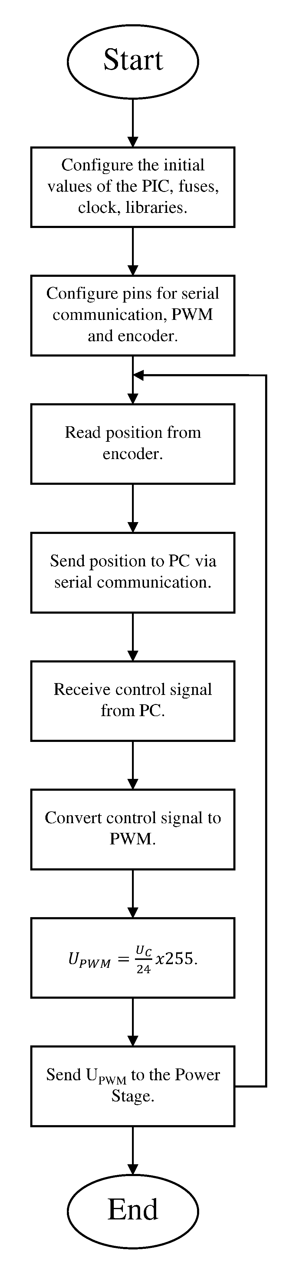
4.2. PIC Programming

The Integrated Development Environment (IDE) selected to program the PIC is PIC C which has been created by PIC CMU. The reason for using this IDE is because it has different libraries and drivers that facilitate the programming. In addition, PIC C uses the C language as opposed to assembly language. Figure 3 presents the steps to follow to start up the dsPIC. The headers must be specified for the type of PIC, the required libraries and the address of port B that is adopted as an interrupt for the encoder reading must be specified.

4.3. Library for Membership Functions

The objective of this section is the creation of a library or file in C language that contains the mathematical description of all types of membership functions.
This part helps the student in the implementation of the final code, since it synthesizes all the membership functions in one place, replacing the need to define them completely each time it is required. However, the student will decide whether to make such a library or to add the functions to the beginning of the main code, based on his cultural background. The equations for each function must be added to define the degree of membership.
  • The triangular function is defined by Equation (10).
    μ A ( x ) = { 0 , if   ( x a ) x a m a , if   ( a < x m ) b x b m , if   ( m < x < b ) 0 , if   ( x a )
  • The trapezoidal function is defined by Equation (11).
    μ A ( x ) = { 0 , if   ( x < a ) o r ( x > d ) x a b a , if   ( a x b ) 1 , if   ( b x c ) d x d c , if   ( c x d )
  • The Gaussian function is defined by Equation (12).
    μ A ( x ) = e ( x m ) 2 2 k 2
  • The R-Function is defined by Equation (13).
    μ A ( x ) = { 0 , if   ( x > d ) x a b a , if   ( a x b ) 1 , if   ( x < c )
  • The L-Function is defined by Equation (14).
    μ A ( x ) = { 0 , if   ( x < a ) x a b a , if   ( a x b ) 1 , if   ( x > b )

4.4. Control Loop Construction

The segment proposes the creation of the control loop illustrated in Figure 1, selecting the power stage, encoder, motor and connections.
The motor selected to carry out the project is model f2260 from the Maxon company; its specifications are exposed in Table 4. The motor selected for the application handles a maximum current of 16 A. The power stage must be designed to withstand this intensity. In addition, a 12 V supply voltage is utilized with a model BTS7960B H-bridge.
As shown by the characteristics of the motor selected for the project, a maximum current of 16 A is needed to activate the motor. The selection of the power stage should comply with this requirement besides working with 12 V, which is the motor supply voltage. A H-bridge model BTS7960B was selected to satisfy the power needs. It is recommended to employ a commercial circuit already assembled such as the IBT_2 model H-bridge for the Arduino platform, which internally contains the BTS7960B bridge and control components that allow it to have the following characteristics:
  • Operating voltage 5–27 V
  • Motor speed control through PWM frequency up to 25 kHz
  • Control in both directions of the motor
  • Maximum current capacity up to 30 A
Table 5 presents the connection pins of this H-bridge to the acquisition card. Pins 3 and 4 are always active and pins 5 and 6 are not used.
The position of the motor is obtained from an encoder from the Yumo company and the B950 model was selected. Its characteristics are listed below:
  • An operating voltage of 5–24 V of direct current
  • A resolution of 1024 PPR
  • Z signal that can be easily adjusted
  • It has protection against short circuits
  • Maximum current consumption of 70 mA
  • Three exit signs A, B and Z
  • Open collector output configuration
  • Maximum frequency response of 100 kHz
  • 20 Ω insulation resistance
As mentioned above, the encoder signals are connected to pins 24 and 26 of the dsPIC that correspond to port B, using the encoder quadrature, which consists of the microcontroller reading both signals A and B from the encoder and, depending on which one is read first, determines the direction of rotation of the motor. The Z signal is not used in this project.
In order for the student to interact with the controller results, a Graphical User Interface (GUI) is provided. The GUI files are “union.fig” and “union.mat”, which can be downloaded from [48]. The GUI consists of two main buttons. The “system behavior” button displays the buttons to observe the desired value and the real value, the error value and the control signal, as illustrated in Figure 4. Figure 5 exposes how the button of “fuzzy logic” allows the student to observe the membership functions for the input and output variables, as well as the rules implemented for the inference engine.
Figure 6 shows the complete system and the connections required for the correct operation.
As shown in Figure 6, it is necessary to utilize a USB-Serial converter for which the model pl2303 of the Ranmex brand was selected. This model has in pins 5 and 4 the supply voltage and ground, respectively. Pin 3 is the transmission (Tx) and it is connected to the reception (Rx) of the DAQ. This converter is responsible for powering the DAQ. Pins 4 (GND) and 5 (VCC) of the converter are connected to pins 28 and 27 of the DAQ delivering a voltage of 5 V , enough to power the encoder.
Once energized, the DAQ reads the A and B signals of the encoder on pins 24 and 26 and adds the necessary voltage (5 V) to activate the control pins of the H-bridge. Pins 3 and 4 of the H-bridge that correspond to the activation of the rotation to the left and right are permanently activated; they connect directly to VCC. Finally, pins 23 and 25 of the DAQ are the PWM outputs ( U P W M ( s ) ) connected to pins 1 and 2 of the H-bridge and indicate the direction and speed at which the motor should rotate. These signals have a range of 0–5 V.
In the same way, an external voltage source is used to supply the power of the H-bridge. This source is connected to pins 9 and 10 that correspond to the positive and negative terminal, respectively. Even though the operating voltage is 12 V, the actual value delivered due to component losses is 10 V, which corresponds to the maximum value that the signal U M ( s ) can reach.

4.5. Design of the Fuzzy Controller

The objective is to design the three stages of a fuzzy controller, fuzzification, rules and defuzzification.
As shown in Figure 1, there is a desired angular position value θ * and the actual value measured by the encoder θ is fed back. The error E ( s ) is obtained according to Equation (15). Then, E ( s ) is the first input variable for the fuzzy controller and its membership functions are defined by Figure 7a, which consists of three triangular functions, an R-function and an L-function, with a range from 50 to 50 π r a d .
E ( s ) = θ * ( s ) θ ( s )
For this project, another input variable was selected, which is the weight that is added to the motor shaft. Its membership functions consist of a trapezoidal function, an L-function and an R-function. The range of this variable is from 0 to 30 kg. These are displayed in Figure 7b.
Finally, for the output variable three triangular functions, an R-function and an L-function are selected; the range is 10 to 10 V. Membership functions for the output variable are exhibited in Figure 7c.
The rules for fuzzy controlled are defined in Table 6.
The chosen method for defuzzification is the Center of Area (CoA), which is described in Equation (16). CoA is the center of the area, x is the value of the linguistic variable and x m i n and x m a x represent the range of the linguistic variable. In the CoA, the controller calculates the area of the membership functions and within the range of the output variable.
C o A = x m i n x m a x f ( x ) x d x x m i n x m a x f ( x ) d x = U c

4.6. Implementation of the Controller

The objective of this section is to integrate all the previous elements and develop the main code to implement the final controller.
This portion is the final stage for the complete development of the project and consists of integrating all the elements previously developed and the elaboration of the main code, which is recommended to be developed in C language. A computer is the element in charge of performing all the previously described controller calculations.
An HP computer, model Pavilion G4 with an Intel Pentium Inside B950 processor, was selected. The processor specifications are as follows:
  • Two cores
  • Two threads
  • Processor Base Frequency of 2.10 GHz
  • Cache 2 MB L3
  • BusSpeed 5 G T s
In addition to the above, the operating system of the computer was Windows 7, and the RAM was 6 GB. It is important to note that it is not necessary to use the same computer. However, it is recommended to choose one with at least the same characteristics to ensure the correct operation of the project. One limitation of this research was to find a computer with Windows XP, where the controller for the converter was made, but the closest operative system found was Windows 7. The controller does not work in the Windows 10 version. Figure 8 shows the flow chart of the steps to perform the code.

5. Indicators

The proposed rubric for this project seeks to meet the standards required by ABET regarding student outcomes, which must be effectively documented for a periodic review. According to the requirements, the project is defined by the practical problem of performing a position control using traditional components for the power and acquisition stages, limiting the control stage to the use of fuzzy logic; on the other hand, even when a way of implementing the fuzzy controller is proposed, it is emphasized that there are infinite different proposals for the membership functions, rules and defuzzification method. It is for this reason that the rubric is divided as shown in Table 7, where the outcomes are those required for the associate degree programs from ABET with slight modifications to suit the specific program implemented by the engineering faculty of the Universidad Autónoma de Querétaro with regards of the values and objectives.
For the intelligent control class according to Table 7, Indicators I and II were evaluated by the application of a written exam. The score of Indicator III was obtained according to the ability of the student to carry out the required experimentation. Indicator IV evaluated the programming knowledge of the learners according to the implementation of the program. Finally, Indicator V was based on the final written report of the laboratory. The analysis of the results obtained by students during four periods was carried out and the results according to the rubric proposed for this project are denoted in Table 8.

6. Conclusions

Nowadays, the use of electric motors has increased considerably. In the industrial area, it is one of the most used final action elements. In this sector, the motors can be part of industrial fans, blowers and pumps, machines, tools, etc. However, the use of these devices is currently not limited to the industrial area. The rise of renewable energies is driving the use of electric motors in the transport sector around the world. It is important that engineering students, specifically students in automatic control, are familiar with this type of actuator and its control.
The research presented addresses the control, by students, of a direct current motor by applying non-classical control techniques. In this way, a broader panorama of the different methods that can be applied to control similar devices developing transferable skills and extrapolate the knowledge to a wide range of engines. Although the motors can be of different shapes, sizes, power, etc., all are based on the same principle, the conversion of electrical energy into mechanical energy.
The objective of the student is to develop the project in a modular way, which is why it was divided into different practices to meet the necessary criteria for ABET certification. This certification is important to participate in the global labor market with the equity required disregarding the country and the culture of the students. The results obtained prove that there is a slight improvement in the grades obtained by the students who took the course. In addition, due to the multidisciplinary nature of the project, the necessary skills are granted to work in a team, build their own acquisition cards without the need to buy trademarks, reinforce prior knowledge about programming languages, design control loops and mainly design and implement controllers with fuzzy logic, but also with the different approaches each students brings to the team.
It is important to note that the proposed project is a first approach to fuzzy controllers. However, it provides the necessary tools for the student to design their own controllers and experiment with different membership functions to improve system behavior. It is presumed that the disadvantages in Indicators III and IV of Table 7 are due to the fact that the students of that period did not have adequate preparation in the subjects of programming, power circuits, microcontrollers and sensors. This leads to a deeper analysis of how to implement this methodology and how it could be improved to achieve better and more consistent results.

Author Contributions

Conceptualization, H.T.-S.; methodology, H.T.-S.; formal analysis, H.T.-S.; investigation, H.T.-S., A.A.E.-B. and J.R.-R.; resources, J.R.-R.; data curation, H.T.-S., A.A.E.-B. and J.R.-R.; writing—original draft preparation, H.T.-S. and A.A.E.-B.; writing—review and editing, H.T.-S., M.A.C.P., P.Y.S.-C., G.I.P.-S. and A.A.E.-B.; and supervision, J.R.-R. All authors have read and agreed to the published version of the manuscript.

Funding

This research received funding from PRODEP and CONACYT.

Conflicts of Interest

The authors declare no conflict of interest.

References

  1. Babatope, A.; Samuel, T.M.; Ajewole, P.I.; Anyanwu, O.M. Competence-driven engineering education: A case for T-shaped engineers and teachers. Int. J. Eval. Res. Educ. 2020, 9, 32. [Google Scholar] [CrossRef]
  2. Uskov, V.; Bakken, J.P.; Aluri, L.; Rachakonda, R.; Rayala, N.; Uskova, M. Smart pedagogy: Innovative teaching and learning strategies in engineering education. In Proceedings of the 2018 IEEE World Engineering Education Conference (EDUNINE), Buenos Aires, Argentina, 11–14 March 2018. [Google Scholar] [CrossRef]
  3. Choi, Y.; McClenen, C. Development of adaptive formative assessment system using computerized adaptive testing and dynamic bayesian networks. Appl. Sci. 2020, 10, 8196. [Google Scholar] [CrossRef]
  4. Crawley, E.; Malmqvist, J.; Ostlund, S.; Brodeur, D.; Edström, K. Rethinking Engineering Education: The CDIO Approach; Springer: Cham, Switzerland, 2014; pp. 9–10. [Google Scholar]
  5. Cunningham, C.M.; Kelly, G.J. Epistemic practices of engineering for education. Sci. Educ. 2017, 101, 486–505. [Google Scholar] [CrossRef]
  6. Feisel, L.D.; Rosa, A.J. The role of the laboratory in undergraduate engineering education. J. Eng. Educ. 2005, 94, 121–130. [Google Scholar] [CrossRef]
  7. Walther, J.; Miller, S.E.; Sochacka, N.W. A model of empathy in engineering as a core skill, practice orientation, and professional way of being. J. Eng. Educ. 2017, 106, 123–148. [Google Scholar] [CrossRef]
  8. Gunckel, K.L.; Tolbert, S. The imperative to move toward a dimension of care in engineering education. J. Res. Sci. Teach. 2018, 55, 938–961. [Google Scholar] [CrossRef]
  9. Burt, B.A.; Williams, K.L.; Palmer, G.J.M. It takes a village: The role of emic and etic adaptive strengths in the persistence of black men in engineering graduate programs. Am. Educ. Res. J. 2018, 56, 39–74. [Google Scholar] [CrossRef] [Green Version]
  10. Yang, Y. Discussion on the teaching reform of the automatic control theory. In Proceedings of the 3rd International Conference on Science and Social Research, Tianjin, China, 14–15 June 2014; Atlantis Press: Paris, France, 2014. [Google Scholar] [CrossRef] [Green Version]
  11. Cheng, H.; Hao, L.; Luo, Z.; Wang, F. Establishing the connection between control theory education and application: An arduino based rapid control prototyping approach. Int. J. Learn. Teach. 2016, 2. [Google Scholar] [CrossRef] [Green Version]
  12. Han, S.; Capraro, R.; Capraro, M.M. How science, technology, engineering, and mathematics (STEM) project-based learning (PBL) affects high, middle, and low achievers differently: The impact of student factors on achievement. Int. J. Sci. Math. Educ. 2014, 13, 1089–1113. [Google Scholar] [CrossRef]
  13. Trusty, J.; Niles, S.G. High-School Math Courses and Completion of the. Bachelor’s Degree. Bachelor’s Thesis, Professional School Counseling, Alexandria, VA, USA, 2003; pp. 99–107. [Google Scholar]
  14. Hart, G.E.; Cottle, P.D. Academic backgrounds and achievement in college physics. Phys. Teach. 1993, 31, 470–475. [Google Scholar] [CrossRef]
  15. Koh, M.Y.; Koh, H.C. The determinants of performance in an accountancy degree programme. Account. Educ. 1999, 8, 13–29. [Google Scholar] [CrossRef]
  16. Petriz Mayen, M.A.; Barona Ríos, C.; López Villareal, R.M.; Quiroz González, J. Niveles de desempeño y actitudes hacia las matemáticas en estudiantes de la licenciatura en administración en una universidad estatal mexicana. Rev. Mex. Investig. Super. Educ. 2010, 15, 1223–1249. [Google Scholar]
  17. Zamfiroiu, A.; Constantinescu, D.; Zurini, M.; Toma, C. Secure learning management system based on user behavior. Appl. Sci. 2020, 10, 7730. [Google Scholar] [CrossRef]
  18. Moradi, M.H.; Katebi, M.R.; Johnson, M.A. Robust MIMO PID tuning method. In Proceedings of the International Conference on Control Applications, Glasgow, UK, 18–20 September 2002. [Google Scholar] [CrossRef]
  19. Odry, Á.; Fullér, R.; Rudas, I.J.; Odry, P. Fuzzy control of self-balancing robots: A control laboratory project. Comput. Appl. Eng. Educ. 2020, 28, 512–535. [Google Scholar] [CrossRef]
  20. Odry, Á.; Fullér, R.; Rudas, I.J.; Odry, P. Kalman filter for mobile-robot attitude estimation: Novel optimized and adaptive solutions. Mech. Syst. Signal Process. 2018, 110, 569–589. [Google Scholar] [CrossRef]
  21. Odry, A.; Fuller, R. Comparison of optimized PID and fuzzy control strategies on a mobile pendulum robot. In Proceedings of the 2018 IEEE 12th International Symposium on Applied Computational Intelligence and Informatics (SACI), Timisoara, Romania, 17–19 May 2018. [Google Scholar] [CrossRef]
  22. Stefanovic, M. The objectives, architectures and effects of distance learning laboratories for industrial engineering education. Comput. Educ. 2013, 69, 250–262. [Google Scholar] [CrossRef]
  23. Soares, F.; Leao, C.P.; Carvalho, V.; Vasconcelos, R.M.; Costa, S. Automation and control remote laboratory: A pedagogical tool. Int. J. Electr. Eng. Educ. 2014, 51, 54–67. [Google Scholar] [CrossRef] [Green Version]
  24. Swart, A.J. Student usage of a learning management system at an open distance learning institute: A case study in electrical engineering. Int. J. Electr. Eng. Educ. 2015, 52, 142–154. [Google Scholar] [CrossRef]
  25. Rampazzo, M.; Cervato, A.; Beghi, A. Remote refrigeration system experiments for control engineering education. Comput. Appl. Eng. Educ. 2017, 25, 430–440. [Google Scholar] [CrossRef]
  26. Parkhomenko, A.; Parkhomenko, A.; Tabunshchyk, G.; Henke, K.; Wuttke, H.D. The remote labs as an effective tool of inclusive engineering education. In Proceedings of the 2018 XIV-th International Conference on Perspective Technologies and Methods in MEMS Design (MEMSTECH), Lviv, Ukraine, 18–22 April 2018. [Google Scholar] [CrossRef]
  27. Davidovitch, L.; Parush, A.; Shtub, A. Simulation-based learning in engineering education: Performance and transfer in learning project management. J. Eng. Educ. 2006, 95, 289–299. [Google Scholar] [CrossRef]
  28. Akkoyun, O. New simulation tool for teaching-learning processes in engineering education. Comput. Appl. Eng. Educ. 2017, 25, 404–410. [Google Scholar] [CrossRef]
  29. Kezunovic, M.; Abur, A.; Huang, G.; Bose, A.; Tomsovic, K. The role of digital modeling and simulation in power engineering education. IEEE Trans. Power Syst. 2004, 19, 64–72. [Google Scholar] [CrossRef] [Green Version]
  30. Balamuralithara, B.; Woods, P.C. Virtual laboratories in engineering education: The simulation lab and remote lab. Comput. Appl. Eng. Educ. 2009, 17, 108–118. [Google Scholar] [CrossRef]
  31. Alhalabi, W. Virtual reality systems enhance students’ achievements in engineering education. Behav. Inf. Technol. 2016, 35, 919–925. [Google Scholar] [CrossRef]
  32. Salah, B.; Abidi, M.; Mian, S.; Krid, M.; Alkhalefah, H.; Abdo, A. Virtual reality-based engineering education to enhance manufacturing sustainability in industry 4.0. Sustainability 2019, 11, 1477. [Google Scholar] [CrossRef] [Green Version]
  33. Franzoni, V.; Milani, A.; Mengoni, P.; Piccinato, F. Artificial intelligence visual metaphors in E-Learning interfaces for learning analytics. Appl. Sci. 2020, 10, 7195. [Google Scholar] [CrossRef]
  34. Garduno-Aparicio, M.; Rodriguez-Resendiz, J.; Macias-Bobadilla, G.; Thenozhi, S. A multidisciplinary industrial robot approach for teaching mechatronics-related courses. IEEE Trans. Educ. 2018, 61, 55–62. [Google Scholar] [CrossRef]
  35. Cruz-Miguel, E.E.; Rodríguez-Reséndiz, J.; García-Martínez, J.R.; Camarillo-Gómez, K.A.; Pérez-Soto, G.I. Field-programmable gate array-based laboratory oriented to control theory courses. Comput. Appl. Eng. Educ. 2019, 27, 1253–1266. [Google Scholar] [CrossRef] [Green Version]
  36. Inelmen, E.; Inelmen, E.; Ibrahim, A.A. A new approach to teaching fuzzy logic system design. In Fuzzy Sets and Systems—IFSA 2003, Proceedings of the 10th International Fuzzy Systems Association World Congress, Istanbul, Turkey, 30 June–2 July 2003; Lecture Notes in Computer Science; Springer: Berlin/Heidelberg, Germany, 2003; pp. 79–86. [Google Scholar] [CrossRef]
  37. Akcayol, M.A.; Elmas, C.; Erdem, O.A.; Kurt, M. An educational tool for fuzzy logic controller and classical controllers. Comput. Appl. Eng. Educ. 2004, 12, 126–135. [Google Scholar] [CrossRef]
  38. Ibrahim, D.; Alshanableh, T. An undergraduate fuzzy logic control lab using a line following robot. Comput. Appl. Eng. Educ. 2009, 19, 639–646. [Google Scholar] [CrossRef]
  39. Almohammadi, K.; Hagras, H.; Yao, B.; Alzahrani, A.; Alghazzawi, D.; Aldabbagh, G. A type-2 fuzzy logic recommendation system for adaptive teaching. Soft Comput. 2015, 21, 965–979. [Google Scholar] [CrossRef]
  40. Zadeh, L.A. Fuzzy sets. Inf. Control 1965, 8, 338–353. [Google Scholar] [CrossRef] [Green Version]
  41. Wang, L.-X. Design and analysis of fuzzy identifiers of nonlinear dynamic systems. IEEE Trans. Autom. Control 1995, 40, 11–23. [Google Scholar] [CrossRef]
  42. Amendola, C.A.M.; Gonzaga, D.P. Fuzzy-logic control system of a variable-speed variable-pitch wind-turbine and a double-fed induction generator. In Proceedings of the Seventh International Conference on Intelligent Systems Design and Applications (ISDA 2007), Rio de Janeiro, Brazil, 20–24 October 2007. [Google Scholar] [CrossRef]
  43. Mamdani, E.H. Application of fuzzy algorithms for control of simple dynamic plant. Proc. Inst. Electr. Eng. 1974, 121, 1585–1588. [Google Scholar] [CrossRef]
  44. Takagi, T.; Sugeno, M. Fuzzy identification of systems and its applications to modeling and control. IEEE Trans. Syst. Man Cybern. 1985, SMC-15, 116–132. [Google Scholar] [CrossRef]
  45. Kouro, S.; Musalem, R. Control mediante lógica difusa. Téc. Mod. Autom. 2002, 1, 1–7. [Google Scholar]
  46. Rafa, S.; Larabi, A.; Barazane, L.; Manceur, M.; Essounbouli, N.; Hamzaoui, A. Implementation of a new fuzzy vector control of induction motor. ISA Trans. 2014, 53, 744–754. [Google Scholar] [CrossRef]
  47. Torres, H. DAQ for Fuzzy Controller. 2020. Available online: https://github.com/Htorres07/FuzzyController/tree/main/DAQ (accessed on 29 November 2020).
  48. Torres, H. GUI for Fuzzy Controller. 2020. Available online: https://github.com/Htorres07/FuzzyController/tree/main/GUI (accessed on 29 November 2020).
Figure 1. Control loop proposed for the project.
Applsci 10 09070 g001
Figure 2. Minimum circuit required for dsPIC.
Applsci 10 09070 g002
Figure 3. Program flow diagram for the dsPIC.
Applsci 10 09070 g003
Figure 4. GUI screen for system behavior.
Applsci 10 09070 g004
Figure 5. GUI screen for fuzzy logic.
Applsci 10 09070 g005
Figure 6. Complete system required for the project.
Applsci 10 09070 g006
Figure 7. Membership functions proposed for the fuzzy controller.
Applsci 10 09070 g007
Figure 8. Flow chart of the main code actions.
Applsci 10 09070 g008
Table 1. Main investigation presented in the state of the art and their contribution to the field.
Ref./YearStudy AreaContribution to the Field
[27]/2006Simulation environmentThe work presents empirical findings on the impact of maintaining and reviewing the learning history in a dynamic and interactive simulation environment of engineering education.
[22]/2013Laboratories for distanceThe objective of the paper is to present the fundamental objectives of learning through distance learning laboratories as well as the special issues connected with these labs, including their effectiveness.
[23]/2014Perception studyThe paper exposes a study to evaluate perception of the students of the development and use of remote Control and Automation training kits in Portugal.
[24]/2015Learning management systemThe purpose of this article is to highlight student usage of a learning management system in electrical engineering at an open distance learning institute.
[28]/2017Simulation-based softwareIn this study, new simulation-based software developed for educational purposes is introduced.
Table 2. Description of the function of each device.
DeviceDescription
ControllerA fuzzy controller works in a similar way to a conventional system: it accepts an input value, performs some calculations and generates an output value.
DAQThe DAQ takes the signal received from the encoder and performs its conditioning so that it can be compared with the reference position. Additionally, it converts the signal to the controller output and converts it to a PWM signal for the power stage.
Power StageThe power stage operates on the motor, in it is the H bridge that regulates the operation of the motor. Its operation is determined by the on or off of the different switches.
MotorThe motor is the final action target. Through this element, the angular position of the shaft is regulated.
EncoderIt allows coding the mechanical movement of the motor in different types of electrical impulses: binary digital, analog based on a wave, pulses, etc. In this way, the encoder is the interface between the motor and the controller.
Table 3. Practices required to develop the project.
PracticeDescriptionsTime (h)
1. DAQ construction.The student develops the acquisition card using a PIC and its physical circuit necessary to read encoder and implement PWM, in addition to performing serial communication.2
2. Library creation for membership functions in C language.The student develops the library needed to mathematically represent the membership functions and facilitate their application in the main code.2
3. Control loop construction.The student creates the control loop by selecting the required power stage and using the previously developed DAQ.4
4. Design of the fuzzy controller.The student designs the controller defining the input and output variables, as well as the required membership functions and finally the defuzzification process.8
5. Implementation of the controller.The student develops the main code for the implementation of the previously designed controller.8
Table 4. Motor characteristics.
ParametersValues
Nominal voltage12 V
No-load speed2220 RPM
No-load current200 mA
Nominal speed ω ( t ) 1810 RPM
Nominal torque τ ( t ) 276 mNm
Nominal current i ( t ) 2.94 A
Starting current16.6 A
Initial torque ( T i ) 1660 mNm
Max. efficiency77%
Resistance (R)1.44 Ω
Inductance (L)0.56 mH
Table 5. Pin description of H-Bridge.
Pin NumberPin NameDescription
1RPWMPWM signal to turn right
2LPWMPWM signal to turn left
3R_ENEnable turn right
4L_ENEnable turn right
5R_ISOver-current alarm
6L_ISOver-current alarm
7VCCSupply voltage
8GNDGround
Table 6. Rules for the inference engine.
Error/WeightVery Negative (emn)Negative (en)Zero (ecero)Positive (ep)Very Positive (emp)
Light (pl)smpspscerosnsn
Normal (pn)smpspscerosnsmn
Heavy (pp)smpsceroscerosmnsmn
Table 7. Proposed rubric for evaluation.
Specific IndicatorsCriteriaGrade
90–10070–8960–690–59
I. The ability to identify and formulate complex engineering problems.
a. Basic knowledge about control theory.
b. Identification of the position control problem.
c. Basics of different controllers.
d. Controller proposal.
abcdabcaca
II. The ability to acquire and apply new knowledge as needed.
e. Knowledge about control loops.
f. Knowledge of the types of fuzzy logic.
g. Knowledge about fuzzification
h. Applications of membership functions.
i. Knowledge of fuzzy rules.
j. Knowledge about defuzzification.
efghijeghij1. efgh
2. efgi
3. efgj
efg
III. The ability to design experiment and conduct
standard tests, measurements and experiments,
as well as analyze and interpret the results.

k. Design of the fuzzy controller.
l. Sensor implementation.
m. Power stage implementation.
n. Control stage implementation.
o. Interpretation of results.
p. Conclusions.
klmnop1. klmno
2. klmnp
1. klm
2. kln
kl
IV. The ability to understand and apply programming languages
q. Microcontrollers programming
r. Knowledge of the rs232 protocol in c language
s. Construction of the program for the controller
t. Perform code optimization, verification and debugging
qrst1. qrs
2. qrt
qrq
V. The ability to apply written, oral and graphical communication in well-defined technical and non-technical environments, as well as the ability to identify and use appropriate technical literature
u. Write the experiment report.
v. Add good quality images.
w. Add and explain the necessary equations.
x. Explain the results and conclusions.
uvwx1. uvw
2. uvx
1. uv
2. uw
3. ux
u
Table 8. Analysis of student performance in the Intelligent Control course.
Specific Indicator2018(2)2019(1)2019(2)2020(1)
I60707080
II60808090
III65807090
IV75757080
V80809090
Total average68777686
Publisher’s Note: MDPI stays neutral with regard to jurisdictional claims in published maps and institutional affiliations.

