1. Introduction
The forging hammer is preferred in metal forming because of its strong process adaptability, simple structure, convenient manipulation, and low investment cost. Since the birth of the first steam hammer in England in the 19th century, the forging hammer has been undergoing continuous technological transformation and upgrading, and has experienced many development stages, i.e., the air hammer, steam-air hammer, electrohydraulic pneumatic forging hammer, and all-hydraulic forging hammer [
1,
2,
3]. During these stages, the shortcomings of the high energy consumption and large vibration of forging hammers have been significantly improved through increasing efforts of several generations of researchers. However, as reported by Espinoza [
4] and Altan [
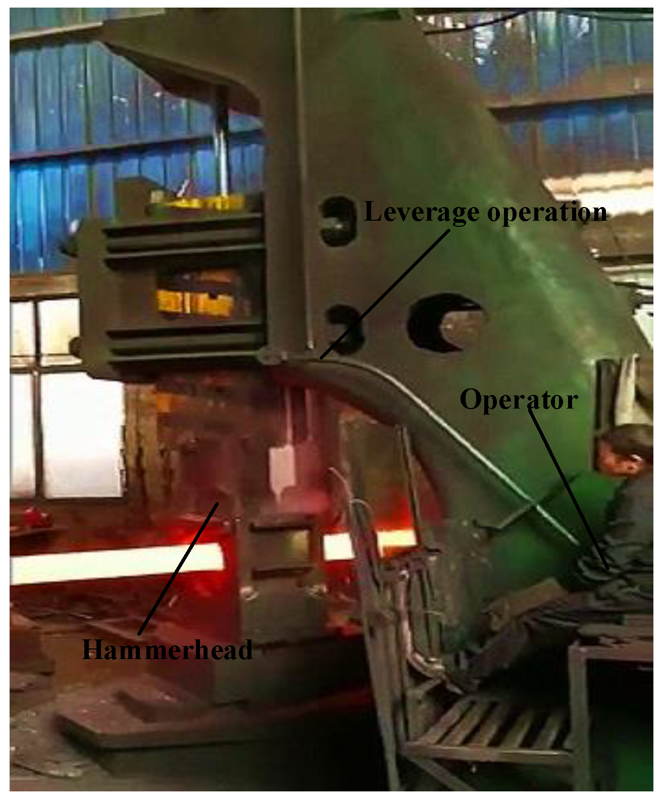
5], several shortcomings still exist that cannot be solved, i.e., the low machining accuracy, high safety hazards, and low degree of automation, as shown in the
Supplementary Materials and
Figure 1. As the most versatile forging equipment, it is of great significance to improve the processing performance of the forging hammer production process.
To deal with the problems mentioned above, much research has been conducted to improve the control performance of the hydroforming equipment. Yao et al. [
6] proposed a new compound control strategy of displacement and dual-pressure for the conventional electro-hydraulic proportional valve controlled fast forging system, and the results showed a significant energy saving effect. Kong et al. [
7] employed a PID controller, integral separation controller, and fuzzy PID controller to control a 0.6 MN forging hydraulic press, and used simulation and experimental methods to study the control characteristics of the forging hydraulic press force closed-loop system under different control methods. The results show that the fuzzy PID could obtain better control effect and significantly improve the performance of forgings. Hao et al. [
8] designed a self-tuning PID controller based on improved BP neural network, which could effectively suppress the time-varying system parameters, external interference, and other factors, thereby improving the dynamic quality of the smoothing mill closed-loop control system. Li et al. [
9] studied the servo control principle of a novel die forging hammer and proposed the energy storage indirect conversion control method and conversion principle, which were shown to significantly improve the system energy efficiency and the controllability of the blow energy. Gerretsen et al. [
10] compared the force closed loop, position closed loop, and speed closed loop control of forging hydraulic equipment, and provided theoretical guidance for subsequent references. Lizalde et al. [
11] combined the second-order sliding mode control method with the neural network control scheme to study the force tracking performance of the electro-hydraulic control system, which significantly improved the machining accuracy of the equipment. Based on Lyapunov analysis, Alleyne et al. [
12] proposed a new simplified algorithm to compensate for the uncertainty of the electro-hydraulic closed-loop control system and carried out experimental verification on a force/displacement servo hydraulic system.
Furthermore, researchers also focused on the energy model to improve the processing performance of the forging hammers. Zhang and Liu [
13] presented a mathematical model of the full hydraulic die forging hammer based on the momentum theorem and then provided a theoretical reference for setting the blow energy and realized precise control of the die forging hammer operation process. Jin et al. [
14] established a mathematical model of the 50 kJ die forging hammer’s striking energy and obtained the relationship between the striking stroke and the striking energy under a certain inflation pressure and mold loading height, providing a basis for program control of the hydraulic die forging hammer. Zhang et al. [
15] developed an energy model for the opening time of the blow valve and the blow energy, which provides a reference for the program control of the die forging hammer and achieves good performance in the open loop control of the die forging hammer. Li et al. [
16] established a new model of the die forging hammer based on the elastic deformation of the cushion under the anvil and deduced a theoretical calculation formula of the maximum hammering force, which provided a reference for the design and use of the die forging hammer. Electrohydraulic forging hammers can be divided into free forging hammers and die forging hammers and configurations of die forging hammers have been optimized by the above methods. However, improvements of the free forging hammer have rarely been reported thus far.
In addition to these methods, researchers have also focused on processing conditions and hammerhead compositions to improve the energy efficiency and processing performance of forging hammers. Jonas [
17] studied the influence of friction on the forming effect of die forging hammers, and the results show that the upper mold achieves the best filling effect when the friction coefficient of the upper mold is about 0.2 and the friction coefficient of the lower mold is the maximum. Ren et al. [
18] employed the continuous damage mechanics theory to analyze the fatigue damage problem of the forging hammer foundation system and provided theoretical guidance for the engineering application of the forging hammer. Lavrinenko and Shagaleev [
19] studied the effect of the forging hammer composition on the deformation efficiency of lead workpieces and pointed out that a hammerhead filled with steel balls could improve the blow efficiency. Irisarri and Pelayo [
20] proposed a failure detection method for the free forging hammer and pointed out that several ductile dimples would appear in the overload area, thereby resulting in fatigue cracks and hammer failure. The core aim of these methods is to improve the processing performance of the forging hammer by optimizing the composition and production environment through finite element analysis of the forging hammer equipment.
Since the die forging hammer works intermittently and the workpieces are formed by molds in which the mold height and manufactured parts are all relatively fixed, the forming energy changes between different working cycles are regular. Therefore, it is easy to realize program control for the die forging hammer. By controlling the opening time and beat of the blow valve, the blow energy and blow step can be controlled as required. Furthermore, the machining accuracy and control performance are significantly improved based on a variety of optimization algorithms, and all forming actions of a die forging hammer are completed by control buttons and programs. Therefore, most of the new die forging hammers on the market nowadays are programmed die forging hammers. However, because of the large randomness of the process requirements in the production process of free forging hammers, the energy changes frequently between different steps, and the strike frequency is faster than the die forging hammer. Therefore, the control method applied to the die forging hammer cannot adapt to the working mode of the free forging hammer, and it is difficult for the free forging hammer to realize its automatic control by adjusting the opening time and beat of the blow valve. As can be seen from
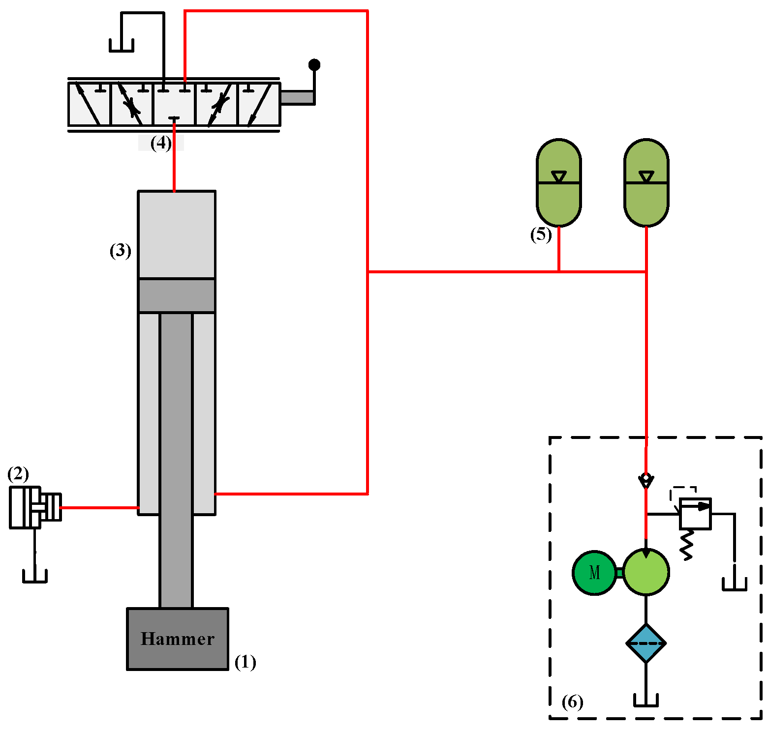
Figure 1, motions of a free forging hammer are still realized by manually operating a set of lever mechanisms in front of the forging hammer, of which the working principle are shown in
Figure 2. The operator continuously manipulates the forging hammer for a long time (80 times/min), and another operator controls the forging manipulator on the operating car, leading to a high labor intensity, strong heat radiation, a high level of noise, and a low processing accuracy of a free forging hammer.
In order to address this problem, this paper proposes a servo control scheme to realize the automation of the free forging hammer and improve the shortcomings mentioned above. A novel free forging hammer structure for this control scheme has been constructed. Automatic control and linkage control can be realized by a single-acting differential servo cylinder drive system and centralized processing of the real-time measurement of the hammerhead position and the reference routes. Moreover, high precision control of the striking energy can be achieved by a Fuzzy PID control scheme, which significantly improves the machining accuracy and shows a high tracking performance of the hammerhead.
The remainder of this paper is organized as follows. In
Section 2, the automatic control methodology is described. The system structure and dynamic performance analysis are developed in
Section 3. In
Section 4, control schemes for free forging hammer are described, including blowing energy model and control strategy. Case study and results are presented in
Section 5. Finally, conclusions are stated in
Section 6.
2. Methodology
The above two forging hammers are controlled by manual operation of the slide valve. If a novel controller can be developed and used to substitute traditional manual control, then automatic control of the forging hammer can be realized. However, due to the randomness of the production process of the free forging hammer, the energy required between different working steps is different. Therefore, it is impossible to realize automatic control for the free forging hammer by the approach used in the current die forging hammer.
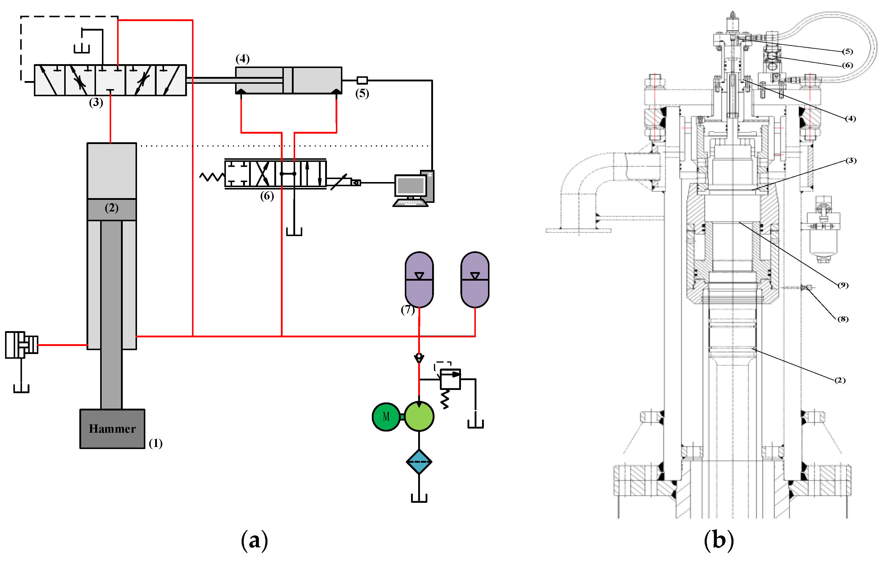
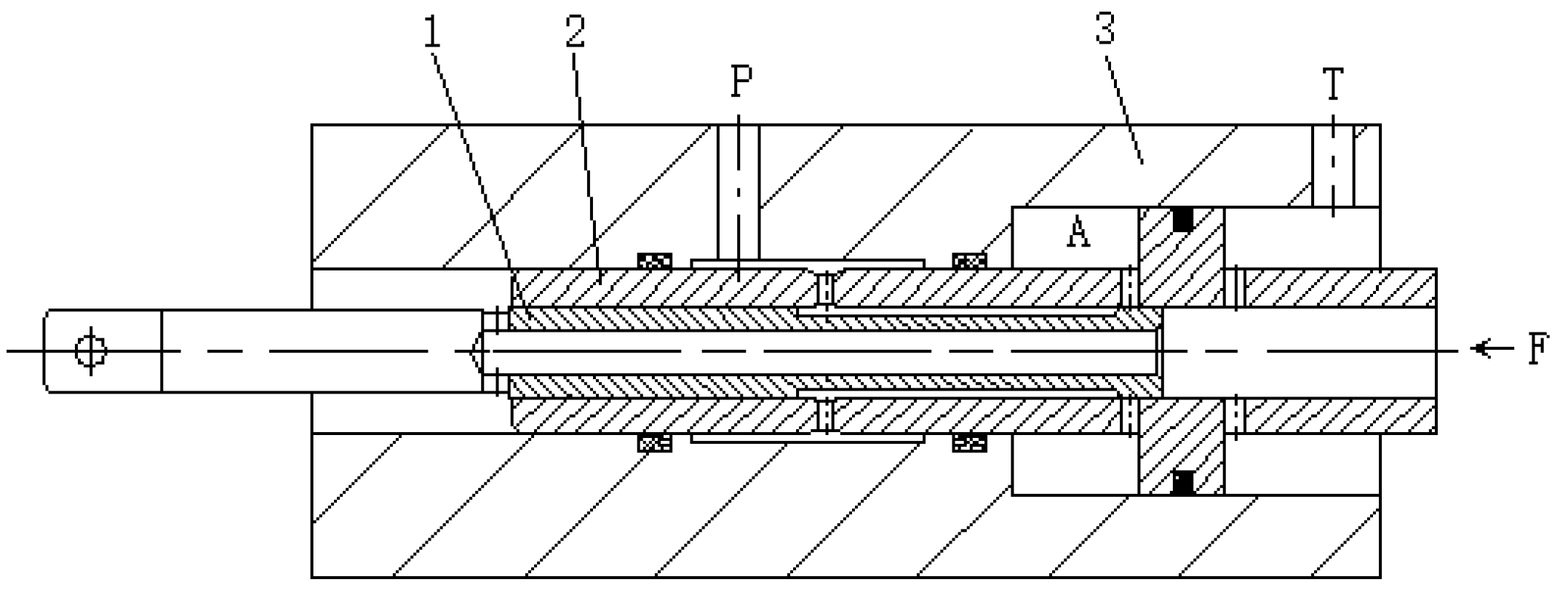
In fact, motions of a free forging hammer are controlled by a main control valve, namely the manual slider valve. Therefore, automation of a free forging hammer can be achieved through automatic control of the main control valve. However, as the manual slide valve has a transition state and is infinitely variable, the valve opening size and the valve on-off state can be accurately controlled by a servo control system. In this control system, movement of the main control valve spool is controlled by a servo cylinder instead of a traditional manual drive, in which the servo cylinder is controlled by an electrohydraulic servo valve. Based on this method, the hammerhead motion state composed of stopping, slow rising, slow falling, returning, and striking with different frequencies and routes can be realized automatically.
Figure 3 is a schematic diagram of the electro-hydraulic servo control system.
As shown in
Figure 3, the main control valve 1 is employed to control the motion state of the hammerhead. According to the opening size, the spool speed and the on–off state of the main control valve 1, hammerhead motions composed of fast falling, pressure with slow falling, pressure maintaining, fast returning, slow returning, and other actions can be accurately realized. To achieve an automatic free forging hammer, the movement of the valve 1 spool is driven by a servo valve 4 controlled single-action servo hydraulic cylinder. Compared with traditional manual control of slide valve 1, not only the control accuracy, but also the manipulating agreeableness are significantly improved. Displacement sensor 3 is employed to measure the position of servo cylinder 2, and the real-time measured data are uploaded onto the upper PC after processing. Then, the upper PC sends a control signal to servo valve 4 under the overall consideration of the current position data from sensor 3 and a required position signal for the following operation. In this servo control system, the response speed and the advance site of cylinder 2 completely follow the given command signal from the controller. Furthermore, the position signal of the hammerhead is also detected, and then fed back to the controller. By analyzing the differential value between the actual position and the reference position, a control signal employed to adjust the hammerhead trajectory is sent to servo valve 4 to change the motion state of servo cylinder 2 and main control valve 1, thereby realizing the automatic operation of the free forging hammer according to the set parameters. The relevant control algorithm will be discussed in the following section.
Figure 4 presents a control diagram of the electro-hydraulic free forging hammer.
The striking speed of the free forging hammer is up to 9 m/s, which produces a large impact and vibration on the forging hammer body and foundation. If the position detection device is installed on the hammer body, the sensor is easily damaged due to the large instantaneous acceleration, and the measured data contain a lot of noise, which poses a great challenge to the subsequent processing.
Therefore, this paper proposes a non-contact displacement measurement system based on the photoelectric effect to measure the position of the hammerhead. The measuring sensor is installed on the bracket drawn from the top of the operating room, which uses the movement of the forging hammer to block the light, and converts the light signal into an electrical signal output so as to obtain the real-time position of the forging hammer. In this detecting system, the measuring sensor is isolated from the hammer body and the foundation, and the impact and vibration during striking do not affect the measuring accuracy of the sensor. Meanwhile, the sensor installation does not affect the on-site operation, and the on-site operation does not damage the sensor. On the premise of not affecting the measurement accuracy, it is beneficial to protect the measurement sensor and prolong its service life.
5. Case Study and Discussion
To illustrate the machining performance and control precision of the proposed free forging hammer, a test verification platform was set up, as shown in
Figure 14, consisting of a control station mainly containing a host industrial computer and an operating handle, host equipment containing a forging hammerhead (whose mass was 760 kg), two displacement sensors (PY102C), a servo control valve (ATOS DLKZOR), a servo cylinder whose stroke was
30 mm, a main working cylinder whose stroke was 1 m, an A/D card (Advantech PCI-1716), and a D/A card (Advantech PCI-1723). In addition, the control system, with a 250 Hz sampling frequency, was composed of monitoring software and real-time control software, and this sampling rate was employed for both data collection and system control.
5.1. Experiments
Three sets of comparative experiments are described in this section, for which the trajectory references were set as 0.3 m, m, and m, respectively. The first command aimed to illustrate the dynamic performance of the proposed system under a unit step response, the second command was set to evaluate the performance of a normal-level motion trajectory (constant forging process), and the third one tried to verify its performance for a fast motion trajectory (fast forging process).
To evaluate the effectiveness of the proposed free forging system, the following three controllers were tested and compared:
- (1)
TC: This is the traditional controller (TC) without any other adjustment during the control process, in which the position of the main cylinder is adjusted by the given pass or an operating handle;
- (2)
PID: This is the Proportional–Integral–Derivative controller. The key parameters , and are tuned by trial and error methods and set as 100, 200, and −5, respectively;
- (3)
Fuzzy-PID: This is the composite controller, which combines the PID controller and fuzzy controller. PID parameters are tuned online by the fuzzy controller, in which the specific fuzzy rules are shown in
Table 2.
5.2. Results
Through simulations and experiments, the results of the first set were obtained and are shown in
Figure 15, the second set are given in
Figure 16, and the third set are depicted in
Figure 17. In addition, their performance indices are presented in
Table 3,
Table 4 and
Table 5, respectively, where
,
, and
are the indices of the average, maximum, and standard deviation of the tracking errors, respectively, and
is the average output of the controller.
As shown in
Figure 15, the three controllers have different overshoots under the trigger of the step signal, where TC is the largest and Fuzzy-PID is the smallest. Since there is no preprocessing with the steady-state error and response speed in TC, the performance of TC is worse than the other two controllers. By comparing the performance indices of the three controllers, although the
of TC is the smallest, the forging hammer system with TC has a poor anti-interference ability and large fluctuations of up to 9 mm, having a great influence on the machining accuracy. Due to combining the reference signal and the feedback signal, PID possesses a certain robustness for dealing with the interference items and some uncertainties to some extent, thereby reducing the steady-state error and improving the response speed of the hydraulic system. However, PID is worse than Fuzzy-PID in terms of all indices. Namely, the proposed fuzzy-PID achieves the best control performance. By online self-tuning of the PID parameters according to the deviation between the reference and the real-time measured data,
and
were significantly reduced compared with PID. The mean tracking error and the maximum tracking error was reduced to less than 2.59 and 6.42 mm with less control efforts compared with PID controller, respectively.
To further test the dynamic performance and the steady-state performance of the proposed free-forging hammer system, the hammerhead was moved along a sinusoidal trajectory.
Figure 16 gives the tracking results of tracking
with the three controllers compared and their performance indices are presented in
Table 4. Compared with Fuzzy-PID, TC and PID produced large overshoots in each stroke, and the hammerhead fluctuated greatly during the downward stroke, leading to a tracking error of up to 70 mm and a low machining accuracy. However, things were significantly improved after adding fuzzy control, and as a result, the maximum overshoot of fuzzy-PID was only 1.6 mm.
In addition, in order to verify the processing performance of the proposed free forging hammer system under fast forging conditions, a fast forging sinusoidal trajectory
was employed. According to experimental results presented in
Figure 17 and
Table 5, the fuzzy-PID controller designed outperforms the other two controllers in terms of the control accuracy and final tracking performance. Based on fuzzy control rules, the overshoot and steady-state error of fuzzy-PID are much smaller than those of conventional PID, and the system fluctuates smoothly. The maximum tracking error is only 22.98 mm. This further proves the effectiveness of the fuzzy-PID control algorithm in improving the processing performance of the all-hydraulic electro-hydraulic servo forging hammer.
In general, the above three sets of experiments have respectively discussed three common working conditions in the free forging process, i.e., constant forging, fast forging, and step response forging, and Fuzzy-PID controller achieves the best performance among the three controllers, as shown in
Figure 18. As can be seen from the above-obtained hammerhead motion trajectory, the hammerhead can move according to the given signal, no matter which control method is adopted, further verifying the effectiveness of the proposed automatic electro-hydraulic servo free forging hammer. By swinging the handle or setting the strike energy and frequency of the system on the upper computer, getting rid of the traditional manual drive and realizing the automatic and remote control of the forging hammer could be achieved. Meanwhile, the forging hammer system monitors the movement positions of the main working cylinder and the servo-driven cylinder, and sends the control signal of the next action after analyzing and processing the given signal, so the processing accuracy of the open forging hammer can be significantly improved.
6. Conclusions
A fuzzy-PID-based nonlinear servo control system has been proposed in this paper for the free forging hammer. The proposed method can address the harsh production environment of the free forging process, backward control methods, low processing accuracy, and inability to adapt to modern production. Changing the traditional control system of free forging hammers has achieved a reduction in personnel and increased the efficiency, which has brought new vitality to the forging hammer and its industry. The effectiveness of the presented method has been verified through serval sets of comparative experiments. Based on the theoretical analysis, simulations, and experiments presented in this paper, the following conclusions can be drawn.
- (1)
Automatic control scheme
A closed-loop control system composed of PLC, an electrohydraulic servo valve, a servo cylinder, and feedback sensors was used to drive the follow-up control valve that controls the motion of the forging hammerhead. Since the reference instruction and the position feedback were employed, the striking energy of each stroke is controlled by the designed controller according to the forging size of the selected pass. After the strike is completed, the hammerhead automatically returns to its original position, and the forging process is completed automatically.
- (2)
High machining accuracy
Based on fuzzy logic rules and PID control methods, high precision control of the striking energy is realized, and the maximum machining error was reduced to 22 mm, which was at least 50 mm less than the traditional free forging hammer.
- (3)
Configuration and structure optimization
Accurate measurement of the real-time position of the hammerhead and the servo cylinder is a key factor for ensuring successful automatic control. As detecting sensors cannot be installed successfully and the measurement data contain a lot of noise due to the vibration and shock generated during the striking process, this paper proposes a non-contact measurement system to address this problem. In addition, optimization of the hammer structure has been achieved for this detecting system and the servo driving system.


