Abstract
At present, the production lines of mobile phones are mainly manual and semi-automatic. Robots are the most important tools used to improve the intelligence level of industry production. The design of an intelligent robotic assembly system is presented in this paper, which takes the assembly of screen components and shell components as examples. There are major factors restricting the application of robots, such as the calibration of diversified objects, the moving workpiece with incomplete information, and diverse assembly types. A method was proposed to solve these technological difficulties. The multi-module calibration method is used to transform the pose relationship between the robot, the conveyor belt, and the two cameras in the robot assembly system. Aiming at a workpiece moving with incomplete information, the minimum matrix method is proposed to detect the position. Then dynamic fetching is realized based on pose estimation of the moving workpiece. At last, the template matching method is used to identify the assembly area of the workpiece type. The proposed method was verified on a real platform with a LINKHOU LR4-R5 60 robot. Results showed that the assembly success rate was above 98%, and the intelligent assembly system of the robot can realize the assembly of mobile phone screens and back shells without any staff.
1. Introduction
Continuous progress of product design concepts has had a great impact on Computer, Communication and Consumer (3C) industry manufacturing technology. Many enterprises are trying to shift production lines from mass production to mass customization. A production system should have the capability to handle smaller batch sizes [1]. As one of the representatives of the 3C industry, mobile phones are an indispensable communication tool in modern life, which have the characteristics of compact design and rapid updating. Phones assembly task is complicated and varied, usually involving many parts and tools (see Figure 1). and there are several challenges [2], which include the display module, camera, battery, and main board. After investigation, the assembly process of mobile phone is as shown in the Figure 2. The mobile phone manufacturing process is manual or semi-automatic, which also leads to high manufacturing costs [3]. The application of robot technology brings opportunities to production line automation. The automation level of phone production lines requires the improvement of robotic technology’s application. If robots replace humans, the labor cost can be greatly saved [4]. However, the assembly parts of mobile phones are various and the robot operation ability is weak [5,6].
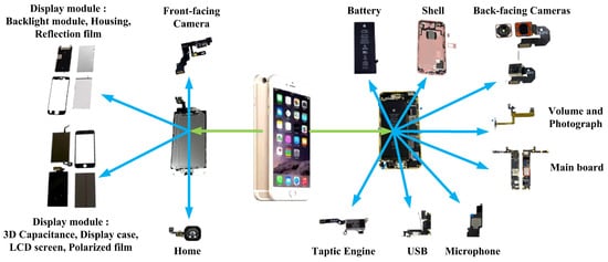
Figure 1.
Composition of mobile phone.
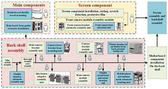
Figure 2.
The assembly process of mobile phone.
Many robotic companies and researchers have been focused on dual arm robots, such as the Baxter robot [7], Yumi robot [8], and NEXTAGE robot [9]. They have been applied in some industrial tasks [10]. However, the dual arm robot with precise hardware is of high cost [11]. Therefore, the signal-arm robot is popular with some companies. There are many difficulties in the process of mobile phone assembly, including pose detection, dynamic grabbing, multi-type assembly, and so on. Vision on the production line is a common set of sensors used to obtain information. The calibration process of a camera is tedious. In addition, sometimes the information of a workpiece being assembled is incomplete. For example, there is often a situation beyond the camera’s field of view [12], due to the cost constraints of the industrial site and the limited manufacturing process of the camera. In addition, the sampling frequency of the camera under a relay trigger does not match the speed of the conveyor belt [13], which also easily causes incomplete image information of the workpiece.
Vision and force sensors are the two common ways for a robot perceive the environment [14]. The mechanical constraints may be used to guarantee the initial position of the workpiece. If the model of the assembled workpiece is changed, the mechanical tools should be different. Machine vision was used to detect the different types of workpieces, which improved the flexibility of the production line [15]. In 2013, the personal household robotic systems, such as HERB and PR2, perceived the surrounding environment and completed some actions, such as cleaning and self-charging with the help of visual sensors [16]. Cai et al. achieved complex movements such as grabbing and placing objects, which combined the multi-degree-of-freedom robot with the active visual positioning system [17]. The target 3D point cloud is segmented by machine vision, and then the trained artificial neural network is combined with machine vision to find the most suitable position for grasping the object [18]. Stephen et al. [19] developed the assembly platform of dynamic binocular visual feedback system. Image servo data acquisition is used as the basis to judge the next visual measurement and guide the assembly of the manipulator. A “precision assembly robot” with a real-time vision system [20] has been developed, and a dynamic target recognition and tracking algorithm based on an improved Camshaft was proposed.
Therefore, the identification and positioning of the workpiece is very important and a lot of work has been done [21]. In [22], a multi-workpiece recognition algorithm was proposed to locate the three-dimensional workpiece of monocular vision in a complex industrial environment, which was based on adaptive sub-pattern manifold learning. Wan et al. [23] taught robots to perform object assembly using multi-modal 3D vision. Compared to 3-D vision, the monocular vision is low cost and easy to implement. For incomplete information workpiece detection, such as exceeding-field of view, Yang et al. designed a super-field component image measuring instrument by using image stitching technology [12]. The adaptive image stitching algorithm was proposed in [24] for panoramic image acquisition of super-field components. In [13], Liu et al. realized the effective recognition of the exceeding-field workpiece by extracting the feature points on the workpiece and conducting shape matching.
In addition, the force control or hybrid position/force control method is commonly used for assembly tasks. In previous studies, there were three classes of control methods: position control, force control, and hybrid position/force control [10,25]. Position control is used to complete the assembly task and vision sensors are widely used to get the positions and orientations of assembly objects [26,27]. The electronic circuit assembly was completed using vision based on OpenCV for an industry robot [26]. The peg-hole assembly was completed through a vision system estimation [27]. The interaction force was obtained by force sensors to guide the robot to complete the assembly [28,29]. Most of the assembly strategies are based on the idea of modeling. A three-point contact model is built, and the pose misalignment between the peg and hole is estimated by force and geometric analysis [30]. A novel modeling method of geometric errors was proposed by Zhang et al. for precision assembly [31]. A control scheme was used to teach the contact states during operation [10]. A robotic assembly parameter optimization method [23,32] was proposed to enable industrial robots to assemble a workpiece.
Compared with the previous work, this paper is aimed at a mobile phone production line process using a robot. A comparative overview Table 1 is listed, which shows the key differences between the different previous systems and the proposed system. The automatic system has also been extensively used in the food industry [33]. There are few references for applying this system to a mobile phone assembly line.

Table 1.
A comparative overview between the previous systems and the proposed system.
In this work, the robot system is proposed to realize the mobile phone assembly process’s automation. At first, a minimum rectangle fitting algorithm is proposed to solve pose estimation problem of moving workpieces with incomplete information. The camera-belt-robot multi-hybrid modular calibration is used to calibrate the assembly system, which could obtain the pose relationship among the robot, the conveyor belt, and the two cameras. Then a posture estimation algorithm on a moving conveyor belt is proposed to track the objects with different speeds. At last, the effectiveness of the method verified that back shell and screen components were assembled with a six-degree-of-freedom LINKHOU.
The rest of this paper is laid out as follows. Section 2 introduces the assembly system description of phone screen components and housing cover. In Section 3, the proposed method is described in detail. Experiments were performed to validate the proposed method, and the experimental results are presented and discussed in Section 4. Finally, the results of the current work were summarized and future directions were discussed in Section 5.
2. System Description
The mobile phone assembly mainly includes three parts: the main board, the screen, and the back shell. The intelligent assembly system is mainly composed of a manipulator, motion module, vision module, and assembly module, as shown in Figure 3. The assembly producer, as shown in Figure 4, should be divided into four steps.
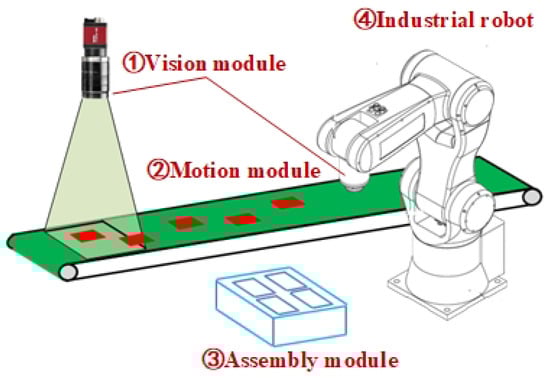
Figure 3.
System composition.
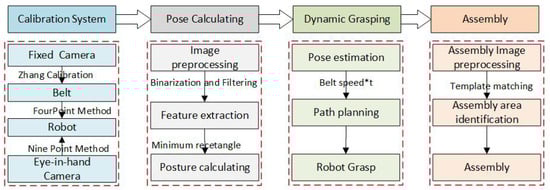
Figure 4.
Assembly production of phone shell.
- Multiple modular hybrid calibration. This mainly includes calibration of the visual system, calibration of the visual system and belt, and calibration of the belt and robot. The whole system coordinate system is realized through transformation.
- Position and posture detection of moving parts. As the motion speed is fast and the shooting lags behind, there are repeated shootings and incomplete information of the target object in the field of view of the camera.
- Dynamic fetching. Due to the different speed of belt movement, the grasping position of the suction cup is deviated during the grasping process. Posture estimation is important for tracking belt speeds.
- Recognize the workpiece to be assembled and the assembly itself. In the area of the workpiece to be assembled, different types of workpieces should be placed. The correct assembly area should be identified first, and then the assembly should be performed.
3. Proposed Method
This section describes the method of the calibration, position detection, dynamic capture, and template matching in detail. Visual guidance is carried out to realize intelligent robot assembly of parts and components of different types under fast beats.
3.1. Multi-Module Hybrid Calibration
Multi-module hybrid calibration mainly includes a robot base coordinate system , an industrial camera coordinate system , and a conveyor coordinate system . Each coordinate system consists of an x axis; y axis; horizontal rotation angle of a workpiece; and the conveyor coordinate system as the calibration link to realize the transformation and unification of the coordinate system, as shown in Figure 5.
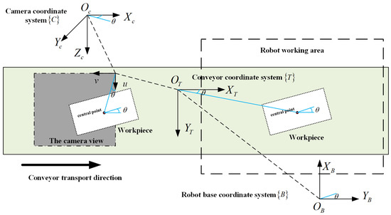
Figure 5.
Relative relations between coordinate systems.
First the vision system uses the calibration plate, combines the HALCON calibration operator, takes Zhang’s calibration [34] method to obtain the camera parameters, and then adopts the nine-point method [35] to obtain the camera’s external parameters. The pose data of the industrial camera coordinate system are represented by in the conveyor coordinate system , and their expression is as follows:
denotes a rotation vector rotated about the Z axis of the conveyor coordinate system, and represents the translation vector along the X axis and Y axis of the conveyor belt coordinate system. The calibration of the vision system and the belt is completed through the coordinate values in the pixel coordinate system converting into coordinate values in the conveyor coordinate system.
Then the marker is placed on the conveyor belt. The initial pose of the marker is recorded, as are the pose after the belt has moved a distance and the number of pulses of the encoder , . The relationship between the two positions is as follows:
As the process of moving the workpiece on the conveyor belt is only x axis translation, with no rotation, the matrix expression of is defined as follows:
where represents the translation distance of the workpiece along the X axis of the conveyor belt coordinate system. The calculation method is as follows:
where M indicates the change of X axis value of an encoder pulse corresponding to the conveyor belt coordinate system. represents the sum of pulses turned by the encoder during the workpiece’s movement.
When the workpiece is detected by the industrial camera, with the advance of the conveyor belt, its position and pose data in the robot base coordinate system of the mechanical arm are expressed as follows:
According to the rotation translation relationship of the coordinate system and the speed of the conveyor belt, the calibration of the conveyor and the robot is completed.
As shown in Figure 6, B is the fixed base coordinate system of the robot arm, E is the end coordinate system of the arm, and C is the camera coordinate system. represents the transformation relationship of the base coordinate system to the calibration coordinate system, including the rotation matrix and the translation vector. can be derived from the robot system. Then the robot was moved to position 1,
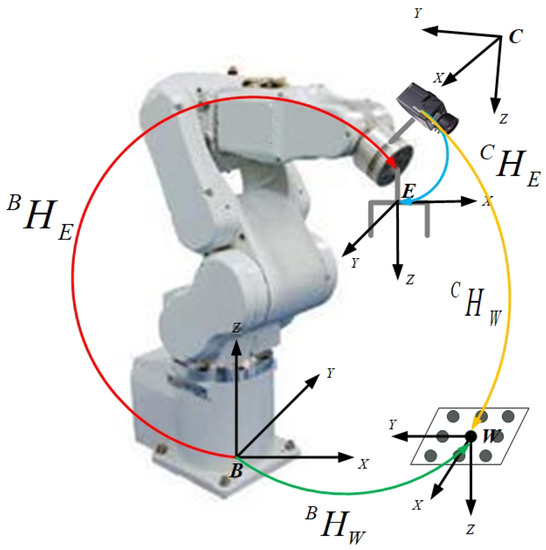
Figure 6.
Hand eye calibration.
Since B and W are fixed, does not change. Therefore:
Make:
Therefore:
Among them, A is known, X is to be sought, and B can be obtained by camera calibration (Zhang’s calibration method) [34].
3.2. Position Detection of Moving Workpiece With Incomplete Information
In the process of moving the target object with the belt, due to the fast moving speed of the belt and the lag of shooting, the target object captured has repeated shooting and incomplete information in the camera field of view. The target recognition method based on the fitting of the smallest rectangular area of the assembled parts is studied, and the edge contour and feature matching are combined to realize the accurate detection of the moving target pose. Before performing contour extraction, image segmentation is performed, and foreground extraction is performed by binarization. The binarization method is as follows:
Set the pixel on the image larger than the threshold to be maximal, and the other pixels to be minimal. The region where the pixel is maximal in the binarized image is the region of interest (ROI). In order to overcome the problem of some tiny black holes in the binarized image, a closed operation process of first dilating and then eroding is required. For the dilate operation:
and for the erode operation:
The target contour is extracted by Canny edge detection algorithm [36]. The performance of this algorithm depends largely on the Gaussian filter and the high and low threshold settings. The Gaussian filter is as follows:
Aiming at the incomplete image problems, an algorithm of the minimum rectangle fitting of feature regions was proposed. Combined with the shape characteristics of the grabbing workpiece, the minimum circumscribed rectangle is used to fit the ROI of the workpiece appearing in the camera field of view, and the actual pose of the workpiece is solved by the eigenvalue of the rectangle.
In the pixel coordinate system, the camera field size is X*Y, the actual length of the workpiece is H pixels, the workpiece center point is , and the position is . The length of the rectangular workpiece fitted in the field of view is h, and the center point coordinate is . The rotation angle of the rectangular area is . The specific mathematical schematic is shown in Figure 7.
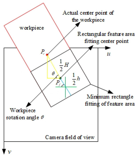
Figure 7.
The schematic of pose estimation.
So the actual workpiece positional relationship is as follows:
3.3. Fast Beat Shooting Dynamic Capture
For the multi-angle measurement of the target workpiece on the belt, the local and global images are switched according to the recognition effect, and the pose parameters of the target workpiece in the robot arm coordinate system are obtained [37], along with the incoming belt displacement and real-time prediction of the pose sequence of the target workpiece. Solving the motion trajectory of the end effector of the robot based on the Kalman filter algorithm [38,39] achieves dynamic tracking of a target workpiece position. Based on the pseudo-inverse solution of the Jacobian matrix, the joint motion velocity of the robot arm is calculated, and a smooth tracking trajectory is generated to achieve smooth grabbing of the target. The crawling process is divided into the following three steps [40]:
- Approaching the target object. The end of the arm reaches the ready position, and the amount of change in the position of the end effector and the target object is calculated. N path points are planned between the two, and the end is accelerated first, reaching the first path point and decelerating to the workpiece speed to synchronize with the target object.
- Tracking target object. The trajectory of the object is the desired trajectory of the end effector of the arm in the Cartesian coordinate space, which is controlled to keep moving, following the object. The joint angle and velocity corresponding to each path point can be solved by the Jacobian pseudo inverse matrix.
- Grab the target object. When the distance from the workpiece meets the requirements, the object is sucked by the air pump to complete the grasping process.
3.4. Fast Beat Shooting Dynamic Capture Method
In the fasten assembly, according to the approach of judging the assembly area in the context of people, the assembly status is evaluated using images and assembly displacements. Images are obtained and preprocessed. Then, the online assembly status is recognized through template matching. The steps are as follows.
- Additional angles of an image are captured using the camera.
- Graying, filtering, and binarization are performed as image preprocessing. The method of weighted average is used to gray the image [41]. After preprocessing the real-time image sequences, a maximum between-class variance method (Otsu’s method) [42] is used to obtain the best treatment threshold for performing the image binarization treatment.
- The processed image is captured in a region of interest [43]. This region can be defined so that the system processing time is reduced, while the real-time processing, reliability, and robustness are improved.
- The assembly quality is identified by the template matching. The common template matching methods are square difference and correlation matching. In this study, template matching is performed via normalized variance of squares matching [44].In the above, is the chosen template, is the target object, is the chosen template, is the target object, and is a function of similarity.
- A recognition result is provided. The performance, based on template matching, depends to a large extent on the quality of the template database.
3.5. Phone Assembly
The overall assembly process is as shown in Algorithm 1 and Figure 8. The mutual conversion relationship between different coordinate systems is established by the modular hybrid calibration of the camera-belt machine. Then, the camera is triggered by the relay to take a photo, and it is detected in real time when there is a workpiece passing through the field of view of the camera, thereby obtaining the posture of the workpiece in the pixel coordinate system. The minimum pose of the feature area is used to solve the actual pose of the workpiece. The system reads the encoder pulse number in real time, sets the robot pre-crawl position, calculates the conveyor moving distance, waits for the workpiece to arrive, and dynamically grabs the workpiece to be loaded based on the model predictive control method to realize the pre-fetch function. Through the calibration of the hand end of the robot arm, the relationship between the position of the arm and the area to be loaded is established. The method of template matching is used to solve the position of the position to be assembled, and the robot arm is guided to the assembly site to realize the assembly function.
| Algorithm 1 Minimum rectangle fitting of the feature area. |
| Initialize parameters: |
| The workpiece position (u, v) |
| Actual position of workpiece (U, V) |
| Workpiece rotation angle |
| while true do |
| Trigger camera to take pictures |
| Extract the rectangular area data of workpiece |
| if then |
| if then |
| else |
| end if |
| else |
| if then |
| else |
| end if |
| end if |
| Convert U,V to base coordinate system data (x,y) |
| Socket communication |
| Robot motion path planning |
| Assembly area template matching |
| Socket communication |
| Converted robot coordinates(x,y)to assembly area coordinates(, ) |
| Finish the assembly |
| end while |
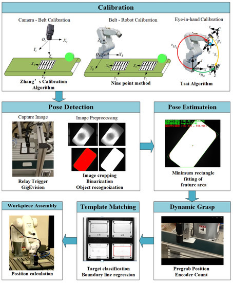
Figure 8.
The assembly chart.
4. Experiments
4.1. Experiments Setup
Experiments were performed to verify the effectiveness of the proposed method. As shown in Figure 9, this system uses the LR4-R560 robot arm of Suzhou LINKHOU Robot Co., Ltd in China. The parameters are shown in Table 2. The basic components include the teach pendant, the mechanical body, and the control cabinet, which are the actuators of the assembly action. The loading part of the mobile phone component assembly consists of a belt and an encoder to form the motion module of the system. The HIKVISION industrial area array camera was used to form a vision module, including a fixed camera with an eye outside the hand and a moving camera with an eye on the hand. This was mainly used to detect the assembly target of mobile phone parts, to realize the positioning of the workpiece to be loaded, and to guide the robot to reach the target position. The assembly module mainly includes an end fixture and an assembly workbench. The system uses suction cup grippers to grab and place mobile phone parts, and the workbench is used to place the parts to be assembled. The system uses the front and rear covers of the mobile phone as the assembly object. Algorithm testing relies on industrial computers with the win10 operating system. Through Hikvision machine vision camera client MVS SDK V2.3.1, C++ language was used to establish communication with the camera. The images collected by the camera are processed by the Halcon operator using C# language. Communication was established with the robot through Transmission Control Protocol/Internet Protocol (TCP/IP), and control the robot to grasp the workpiece. The programs were run in Visual Studio 2013.
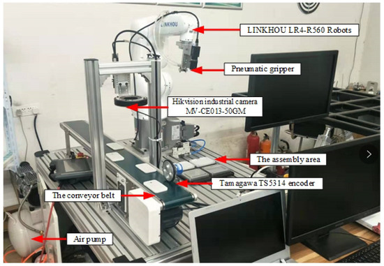
Figure 9.
Platform of the dynamically grasping system.
Table 2.
Robot performance parameters.
4.2. Multiple Modular Hybrid Calibration and Pose Detection
In the field of view of the camera, 15 to 20 Halcon calibration photos with different attitudes were taken, and the coordinate system axis with the belt direction of positive along x was selected as the reference coordinate system of the conveyor. Then, the feature information of the calibration plate was extracted and the external parameters of the camera were calculated. The transformation relationship between the robot base coordinate system and the conveyor belt coordinate system can be obtained by reading the robot base coordinate data of the four points in the conveyor belt coordinate system from the teaching device, and the transmission accuracy of the conveyor belt can be calculated as shown in Figure 10. Calibration results are shown in Table 3.
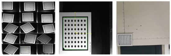
Figure 10.
Camera-conveyer-robot hybrid modular calibration.
Table 3.
Calibration results.
Aiming at two kinds of complete information and four kinds of incomplete information workpieces which may appear in the field of view, the minimum rectangle fitting method is adopted to calculate the actual positions and postures of work pieces respectively, as shown in the Figure 11. In order to determine the accuracy of pose estimation, a mobile phone back shell was placed in the field of view of the industrial camera to trigger the industrial camera to take pictures and calculate the theoretical calculation pose that the robot should reach. Single-step execution of the robotic program: the robotic arrives at the pre-grasp point to wait, opens the conveyor belt to move the back cover of the mobile phone to the optimal gripping position of the robot, and manually controls the end clamp of the robot to reach the center of the back cover of the mobile phone. The actual pose of the robot at this time is recorded and compared to the two pose data.
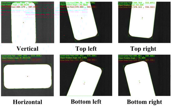
Figure 11.
Pose estimation of an incomplete information workpiece.
From Table 4, the maximum detection error of the uniaxial coordinate data of each workpiece is within 0.5 mm, and the attitude detection error is within 0.8 degree, which meets the technological requirements of the mechanical arm to automatically absorb the back shell of the mobile phone and put it into the area to be assembled with a vacuum chuck. In Liu’s system [13] for workpieces exceeding the visual field, it takes about 6 s to recognize and grab the workpiece. In our method, the speed of the conveyor can be matched to achieve real-time fast grabbing. It costs about 2 s to grasp the workpiece; it can reach with the conveyor speed of 90 mm/s with incomplete information. In terms of accuracy, the horizontal error of our grasping position is about 1mm, which is better to Liu’s system(2s). Compared with special equipment, our robot system is more versatile and can be reused to suit different module assembly requirements in engineering. The cost of industrial production will be reduced, and it is more suitable for small batch, order-based manufacturing needs.
Table 4.
Pose detection results.
4.3. Dynamic grasp
First, the robot was set to the initial position, and the belt was set to 10 mm/s. When the target workpiece moves, the camera calculates the pose of the workpiece, and the speed of the belt is measured. Then, the workpiece target position is estimated. Thus, tracking of the robot arm is generated, and the movement of the robot is controlled so that the end and the workpiece remains relatively stationary for a short time. Finally, after the camera detects that the target workpiece is consistent with the end of the robot, it can suck the target workpiece and capture. The belt rotation speed was set from 50 mm/s to 90 mm/s for comparison experiments. In addition, considering a situation that may occur in practice, a set of variable speed experiments was designed. The belt first moved the workpiece at a lower initial speed (8 mm/s), and then gradually accelerated the belt speed to 90 mm/s to test the gripping effect of the system. Dynamic tracking was achieved with different belt speeds and shifting conditions. The dynamic grasp calibration results are shown in Table 5.
Table 5.
Dynamic grasp results.
4.4. Assembly Area Identification Results
The robotic arm successfully grabs the target workpiece and moves the robot arm to the top of the belt assembly area. The camera on the robotic arm takes a picture of the real-time situation of the assembly area, compresses the real-time image of the obtained assembly area, extracts the ROI area and does other pre-processing, and compares it with the template in the pre-made template library. Opencv and VS2015 were used to obtain the pixel value coordinates and pose of the center point of the area to be assembled corresponding to the back cover of the mobile phone on the image of the real-time area to be assembled, as shown in Figure 12. The coordinates are transmitted to the robot arm through the coordinates of the hand eye calibration, and the assembly of the back cover of the mobile phone is completed.
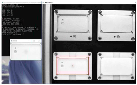
Figure 12.
Results for template matching.
4.5. Assembly test
Assembly experiments were performed at three different speeds of the belt. Two types of materials (metal and plastic) are shown in Figure 13. For the overall assembly process, six groups of experiments were set up. The assembly process is shown in Figure 14. Three initial position experiments were performed (see Figure 15). The average assembly time was 6s. Each group of experiments included 100 rounds of testing the assembly success rate of the robot. From Table 6, the assembly success rate achieved above 98% at different speeds. The industrial robot could flexibly complete various actions in a single action cycle, so it is possible to replace the function of many complex parts in the special assembly machine, which greatly reduces the complexity of assembly. In proposed robot system, the problem of different assembly objects was solved through the pose detection and assembly area recognition algorithms, which were based on machine vision in the assembly process. The assembly of different types of parts was completed with the cooperation of the fixed camera and the hand-eye camera. The target object over the field of view is detected and picked accurately. But the system’s detection accuracy needs to be improved. The reason may be the geometric central points were instead of assembly targets. The better image processing and feature extraction algorithm should be studied in vision system.
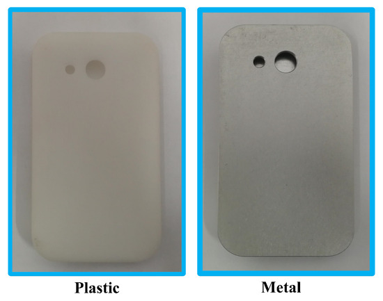
Figure 13.
Two types of materials for the phone.
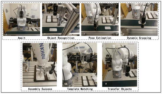
Figure 14.
Overall assembly process.
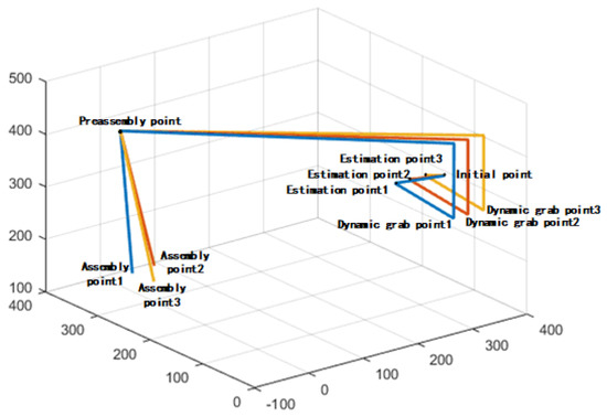
Figure 15.
Robot trajectories of different initial points.
Table 6.
Assembly success rate.
5. Conclusions
This article focuses on the demand of intelligent mobile phone manufacturing in the 3C industry. Certain problems, such as multivariate calibration, dynamic fetching, and identification of the workpiece to be installed, were solved by the proposed methods. Combined with the camera-conveyor-robot hybrid modular calibration, the algorithm of the minimum rectangular fitting of the feature area is used to solve the incomplete workpiece information on the conveyor belt. The motion trajectory of the robot end effector achieves dynamic tracking of the target workpiece position based on the Kalman filter algorithm. The template matching is used to identify the workpiece to be assembled. The proposed methods were performed on the built platform. The experimental results show that the maximum detection error is within 0.5mm and 0.8 degrees. The robot could pick up the workpiece with a success rate of 100% at different conveyor speeds, even though the target component provided incomplete information. Two different phone types were successfully assembled. The key technologies developed in this paper will be applied to the key equipment in the automatic robot production line. This will effectively improve the qualified rate of products, significantly improve market competitiveness of the target products, and have a broad market space.
Author Contributions
R.S. and F.L. conducted the literature review; R.S. and F.L. conceived and designed the algorithm; R.S. and T.F. formulated the mathematical model; R.S. and J.Z. developed the mathematical proof; R.S. and T.F. designed and performed the experiments. All authors have read and agreed to the published version of the manuscript.
Funding
This research was funded by the National Nature Science Foundation of China, grant number 61673245, the Major Science and Technology Innovation Project of Shandong Province, China, grant number 2019JZZY010430, and Major scientific and technological innovation projects in Shandong Province, China, grant number 2017CXGC0915.
Conflicts of Interest
The authors declare no conflict of interest.
References
- Kramberger, A.; Gams, A.; Nemec, B.; Schou, C.; Chrysostomou, D.; Madsen, O.; Ude, A. Transfer of contact skills to new environmental conditions. In Proceedings of the 2016 IEEE-RAS 16th International Conference on Humanoid Robots (Humanoids), Cancun, Mexico, 15–17 November 2016; pp. 668–675. [Google Scholar] [CrossRef]
- Gu, Y.; Sheng, W.; Crick, C.; Ou, Y. Automated assembly skill acquisition and implementation through human demonstration. Robot. Auton. Syst. 2018, 99, 1–16. [Google Scholar] [CrossRef]
- Guo, R. Research on Circuit Board Precision Assembly System Based on Assembly Robot and Vision. Ph.D. Thesis, Beijing Institute of Mechanical Industry Automation, Beijing, China, 2014. [Google Scholar]
- Sierla, S.; Kyrki, V.; Aarnio, P.; Vyatkin, V. Automatic assembly planning based on digital product descriptions. Comput. Ind. 2018, 97, 34–46. [Google Scholar] [CrossRef]
- Yin, Z. Research on Assembly Technology of Small Electronic Product Robot. Ph.D. Thesis, Ningxia University, Ningxia, China, 2016. [Google Scholar]
- Ma, D. Design and Simulation of iNtelligent Positioning and Handling Device for Mobile Phone Production Line. Ph.D. Thesis, North China University of Water Resources and Hydropower, Zhengzhou, China, 2014. [Google Scholar]
- Rethink Robotics Inc. Baxter Robot. Available online: http://www.rethinkrobotics.com/baxter/ (accessed on 1 March 2016).
- ABB Inc. Yumi Robot. Available online: http://new.abb.com/products/robotics/industrial-robots/yumi (accessed on 1 March 2016).
- Kawada Inc. Nextage Robot. Available online: http://nextage.kawada.jp/en/ (accessed on 1 March 2016).
- Ortegaaranda, D.; Lopezjuarez, I.; Nathsaha, B.; Osoriocomparan, R.; Penacabrera, M.; Lefranc, G. Towards learning contact states during peg-in-hole assembly with a dual-arm robot. In Proceedings of the Chilean Conference on Electrical Electronics Engineering Information and Communication Technologies, Pucon, Chile, 18–20 October 2017; pp. 1–6. [Google Scholar]
- Huang, Y.; Zhang, X.; Chen, X.; Ota, J. Vision-guided peg-in-hole assembly by Baxter robot. Adv. Mech. Eng. 2017, 9, 1–9. [Google Scholar] [CrossRef]
- Yang, J.; Zhou, H. Image acquisition optimization method for super field of view based on image pyramid. Mach. Made 2012, 50, 38–41. [Google Scholar]
- Liu, Z.; Wan, P.; Ling, L.; Chen, L.; Li, X.; ZHOU, W. Recognition and Grabbing System for Workpieces Exceeding the Visual Field Based on Machine Vision. ROBOT 2018, 40, 40–46. [Google Scholar]
- Liu, S.; Xu, D.; Zhang, D.; Zhang, Z. High Precision Automatic Assembly Based on Microscopic Vision and Force Information. IEEE Trans. Autom. Sci. Eng. 2016, 13, 382–393. [Google Scholar] [CrossRef]
- Chen, Y. Design of “intelligent manufacturing” flexible production line based on industrial robot. Manuf. Autom. 2017, 55–57. [Google Scholar]
- Hsiao, E. Addressing Ambiguity in Object Instance Detection. Ph.D. Thesis, Carnegie Mellon University, Pittsburgh, PA, USA, 2013. [Google Scholar]
- Cai, J.; Ming, X.; Li, J.; Wang, X.; Tan, W.; Yuan, H.; Hu, S. A Multi-Degree of Freedom Manipulator Based on Active Vision Positioning. Artif. Intell. Robot. Res. 2017, 6, 75–90. [Google Scholar] [CrossRef]
- El-Khoury, S.; Sahbani, A. A New Strategy Combining Empirical and Analytical Approaches for Grasping Unknown 3D Objects. Robot. Auton. Syst. 2010, 58, 497–507. [Google Scholar] [CrossRef]
- Ralis, S.J.; Vikramaditya, B.; Nelson, B.J. Micropositioning of a weakly calibrated microassembly system using coarse-to-fine visual servoing strategies. IEEE Trans. Electron. Packag. Manuf. 2000, 23, 123–131. [Google Scholar] [CrossRef][Green Version]
- Zhong, D.; Yang, Y.; Liu, R.; Han, J. Study and Application of Monocular Vision-Based Assembly Robot. J. Xi’an Jiaotong Univ. 2018, 52, 81–87. [Google Scholar]
- Yang, L.; Chong, M.; Bai, C.; Li, J. A multi-workpieces recognition algorithm based on shape-SVM learning model. J. Phys. 2018, 1087, 022025. [Google Scholar] [CrossRef]
- Li, L.; Wei, X.; Shen, B. 3D workpiece pose estimation based on adaptive sub-pattern manifold learning. J. Jiangsu Univ. 2018, 39, 86–91. [Google Scholar]
- Wan, W.; Lu, F.; Wu, Z.; Harada, K. Teaching robots to do object assembly using multi-modal 3D vision. Neurocomputing 2017, 259, 85–93. [Google Scholar] [CrossRef]
- Gaochao, T. Reserch and Engineering Application of Batch Parts Automatic Detection System Based on Maching Vision. Ph.D. Thesis, Donghua University, Shanghai, China, 2014. [Google Scholar]
- Wu, B. Industrial Robot High Precision Assembly Based on Force Control. Ph.D. Thesis, University of Chinese Academy of Sciences, Beijing, China, 2017. [Google Scholar]
- Korta, J.; Kohut, J.; Uhl, T. OpenCV based vision system for industrial robot-based assembly station: Calibration and testing. Pomiary Autom Kontrola 2014, 60, 35–38. [Google Scholar]
- Lin, L.L.; Yang, Y.; Song, Y.T.; Nemec, B.; Ude, A.; Rytz, J.A.; Buch, A.G.; Krüger, N.; Savarimuthu, T.R. Peg-in-Hole assembly under uncertain pose estimation. In Proceedings of the 11th World Congress on Intelligent Control and Automation, Shenyang, China, 29 June–4 July 2014; pp. 2842–2847. [Google Scholar] [CrossRef]
- Xu, Y.; Hu, Y.; Hu, L. Precision Peg-in-Hole Assembly Strategy Using Force-Guided Robot. In Proceedings of the 2015 3rd International Conference on Machinery, Materials and Information Technology Applications, Qingdao, China, 28–29 November 2015; pp. 1406–1412. [Google Scholar] [CrossRef]
- Roveda, L. Adaptive Interaction Controller for Compliant Robot Base Applications. IEEE Access 2019, 7, 6553–6561. [Google Scholar] [CrossRef]
- Tang, T.; Lin, H.; Yu, Z.; Chen, W.; Tomizuka, M. Autonomous alignment of peg and hole by force/torque measurement for robotic assembly. In Proceedings of the 2016 IEEE International Conference on Automation Science and Engineering (CASE), Fort Worth, TX, USA, 21–25 August 2016; pp. 162–167. [Google Scholar] [CrossRef]
- Zhang, Z.; Zhang, Z.; Jin, X.; Zhang, Q. A novel modelling method of geometric errors for precision assembly. Int. J. Adv. Manuf. Technol. 2018, 94, 1139–1160. [Google Scholar] [CrossRef]
- Chen, H.; Xu, J.; Zhang, B.; Fuhlbrigge, T.A. Improved parameter optimization method for complex assembly process in robotic manufacturing. Ind. Robot-an Int. J. 2017, 44, 21–27. [Google Scholar] [CrossRef]
- Liu, Z. Research on Fast Sorting Food Packaging System Based on Machine Vision. Ph.D. Thesis, Zhejiang University of Technology, Hangzhou, Chin, 2015. [Google Scholar]
- ZHANG, Z. A flexible new technique for camera calibration. IEEE Trans. Pattern Anal. Mach. Intell. 2000, 22, 1330–1334. [Google Scholar] [CrossRef]
- Liu, J. Research on robot Grasping Simulation Training Technology Based On Deep Learning. Ph.D. Thesis, Harbin Institute of Technology, Harbin, China, 2018. [Google Scholar]
- Canny, J. A Computational Approach to Edge Detection. IEEE Trans. Pattern Anal. Mach. Intell. 1986, PAMI-8, 679–698. [Google Scholar] [CrossRef]
- Xie, Y. Research on Robot Dynamic Target Tracking Based on Vision. Ph.D. Thesis, Huaqiao University, Quanzhou, China, 2017. [Google Scholar]
- Gross, R.; Eubanks, T.; Steppe, J.; Freedman, A.P.; Dickey, J.O.; Runge, T.F. A Kalman-filter-based approach to combining independent Earth-orientation series. J. Geod. 1998, 72, 215–235. [Google Scholar] [CrossRef]
- Kalman, R.E.; Bucy, R.S. New Results in Linear Filtering and Prediction Theory. J. Basic Eng. 1961, 83, 95–108. [Google Scholar] [CrossRef]
- Zhang, C.; Shang, W.; Cong, S.; Liu, Y. Motion Planning for Robotic Smooth Catching of Moving Object. J. Mech. Eng. 2018, 54, 193–199. [Google Scholar] [CrossRef]
- Huang, J.; Li, Q. Research and application of binarization algorithms gray-level image under non-uniform illumination. Metall. Ind. Autom. 2017, 41, 13. [Google Scholar]
- Wijnandts, H. Ecological Energetics of the Long-Eared Owl (Asio-Otus). Ardea 1984, 72, 1–92. [Google Scholar] [CrossRef]
- Liu, Y. Research on key Technologies for Binocular Positioning System Based on ROI Segmentation. Ph.D. Thesis, Chongqing University, Chongqing, China, 2018. [Google Scholar]
- Shuai, D.; Liu, C.; Wu, X.; Li, H.; Zhang, F. Image Segmentation of Field Rape Based on Template Matching and K-means Clustering. IOP Conf. Ser. Mater. Sci. Eng. 2018, 466, 012118. [Google Scholar] [CrossRef]


© 2020 by the authors. Licensee MDPI, Basel, Switzerland. This article is an open access article distributed under the terms and conditions of the Creative Commons Attribution (CC BY) license (http://creativecommons.org/licenses/by/4.0/).