Article

Cutting Path Planning Technology of Shearer Based on Virtual Reality

1
College of Mechanical and Vehicle Engineering, Taiyuan University of Technology, Taiyuan 030024, China
2
Shanxi Key Laboratory of Fully Mechanized Coal Mining Equipment, Taiyuan 030024, China
3
Post—Doctoral Scientific Research Station, Taiyuan Heavy Industry Co., Taiyuan 030024, China
*
Author to whom correspondence should be addressed.
Appl. Sci. 2020, 10(3), 771; https://doi.org/10.3390/app10030771
Submission received: 13 December 2019 / Revised: 13 January 2020 / Accepted: 20 January 2020 / Published: 22 January 2020
(This article belongs to the Special Issue Novel Industry 4.0 Technologies and Applications)

Abstract

:
With regards to the low degree of digitization, lack of real geological terrain, and low degree of automation in the cutting process of the traditional virtual fully mechanized mining face, we studied the key technologies of virtual operation and cutting path planning of the shearer on the three-dimensional (3D) roof and floor based on the virtual reality engine (Unity3D). Firstly, the virtual 3D coal seam was constructed through the 3D geological coordinate data of the mine. On this basis, the shape function of the scraper conveyor with the adaptive configuration on the floor was constructed to obtain the combined operation of the virtual shearer and the scraper conveyor. The movement of the shearer’s walking and height-adjustment was then, analyzed. A strategy for automatic height-adjustment based on the adjustment of the direction of the drum movement is hence, proposed to control the cutting path of the shearer. Finally, different experimental schemes were simulated in the developed prototype system after which each of the schemes was evaluated using the fuzzy comprehensive evaluation method. The results show that the proposed strategy for trajectory control can improve the accuracy and stability of the shearer’s motion trajectory. In Unity3D, the pre-selected schemes and digital and visual planning of coal production are previewed ahead of time, the whole production process can be mapped synchronously in the production process. It is also obtained that the virtual preview and evaluation of the production process can provide some guidance for actual production.

1. Introduction

With the advent of Industry 4.0 and Internet Plus, new concepts such as smart mine and digital mine have been continuously proposed. Cloud computing, mixed reality, big data, Internet of Things, and information physics systems have gradually merged with modern industries [1]. Consequently, coal-mining equipment has been continuously transformed into automated, intelligent, and unmanned equipment [2]. Virtual reality is a technology, developed in the 20th century, which involves a computer, electronic information, and simulation technology. Its basic implementation method is to create a simulated environment by computer technologies so as to give people a sense of environmental immersion [3,4]. Due to the unique working conditions of the coal production process, its complexity, and uncertainty, most of the traditional simulation tools and simulation methods are used to simulate a certain process or a single device in the production process, and it is difficult to achieve an overall and real effect, the integration of virtual reality technology into the traditional coal-mining field also presents new demands and broad prospects. Combined with the information from the actual production equipment, assembly conditions, geological environment, and operation data, a realistic three-dimensional (3D) scene was constructed to show and simulate the production process of the fully mechanized mining face [5,6].
The shearer is one of the key equipment for the fully mechanized mining face. It is an important technological equipment to achieve high-efficiency intensive coal mining, reduce major malignant accidents in coal mines, and improve the working conditions of the working face. It is, therefore, of great significance to the virtual simulation of the shearer’s cutting operations. Several studies on the problems of virtual assembly [7], operation demonstration, and attitude analysis [8,9,10] of the shearer in the virtual environment have been carried out. However, most of these studies were carried out under the condition of a horizontal floor. In the real mining process, there are often complex geological conditions such as coal seam dip and undulations in the roof and floor, which leads to the disparity between the equipment operation state presented in the virtual simulation and that in the actual situation.
The planning of the cutting path of the shearer is an important means to achieve intelligent coal mining. At present, the researches on the cutting path planning of the shearer are mainly based on the accurate positioning of the shearer to obtain memory cutting [11,12], and automatic adjustment of drum based on intelligent decision-making or coal rock recognition [13]. Li Wei [14] proposed a hidden Markov model (HMM) memory cutting method for the shearer, which prevented large residual errors and frequent adjustments of the shearer cutting drum. Gospodarczyk Piotr [15] focused on the coal mining process for different variants of the shearer construction and kinematic parameters. Xu Jing [16] proposed an online cutting-pattern recognition method with high accuracy and speed. The cutting sound was collected as the recognition criterion. Although there are many reported studies on the cutting path planning of shearer, those on the demonstration and simulation using virtual reality technology are limited.
The 3D coal seam model is an important aspect to study the virtual operation of the shearer under complex geological conditions. With the help of a 3D visualization platform, the spatial geometry of the geological body in the mining area can be described more accurately and comprehensively by the real 3D coal seam model. Alan M. Lemon [17] developed a 3D geological model based on the drilling data using the horizons method. The user-defined profile method was further used to dynamically modify the geological model. Wu Lixin [18] proposed a generalized triangular prism (GTP) data model for coal seam modeling to solve the problem of geometric cracks. Most of the existing coal mine virtual environment systems are developed by independent GIS Engine [19,20], which makes it difficult for the virtual coal seam to carry out simulation analysis jointly with the shearer and other equipment. In the Unity3D, the 3D coal seam and the fully mechanized mining equipment model are built for joint analysis; all elements of the production process are digitized, and a more comprehensive and real virtual scene is restored for simulation, so as to enhance the actual production.
In an attempt to solve the above-stated challenges, this study was carried out to improve the authenticity and accuracy of simulation. Based on the analysis of the shearer walking and heightening motion model, the equipment modeling and 3D coal seam modeling, combined operation of the shearer and the scraper conveyor were further obtained in the virtual reality engine Unity3D. A cutting path control strategy of the shearer based on adjusting the direction of the drum movement is proposed. Finally, the simulation and the fuzzy comprehensive evaluation [21,22] of the simulation results were carried out.

2. An Idea of Cutting Path Planning Technology of Shearer Based on Virtual Reality

The main technical equipment in the fully mechanized mining face includes shearer, scraper conveyor and hydraulic support. The hydraulic support is mainly used for face advance and supporting the roof of the working face. The shearer and scraper conveyor jointly complete the circular coal cutting. Among them, the scraper conveyor is arranged on the coal seam floor. When the coal seam floor is undulating, the scraper conveyor section by section adapts to the terrain to produce slight bending. The shearer is meshed in the chute of the scraper conveyor through the traveling wheel, which is connected with the scraper conveyor to move forward smoothly, and the shearer sends the drum to the designated position by adjusting the rocker arm to complete the cutting work.
In the selection and design stage of comprehensive mining projects, geological conditions, coal storage, equipment selection, production capacity, and other factors are often considered. Therefore, the selection and design cycle of comprehensive mining face is long and difficult, and coal mining enterprises need to select quickly, and previewed the pre-selected schemes as much as possible, so as to reduce the problems that may occur in the future.
Using the virtual reality engine Unity3D, we studied the cutting path planning method of the shearer drum and obtained the operation simulation of the virtual shearer on the 3D terrain. The overall research framework is shown in Figure 1, which was realized through the following steps.
  • Based on the geometry model, movement model, and rule model of real equipment, the virtual model of the shearer operation was developed, which is completely consistent with reality.
  • The Unity3D engine was used to build the model for the coal seam roof and floor (3D coal seam), and to obtain the orientation of the shearer and scraper conveyor; based on the geometry model, movement model, and rule model of real equipment, the virtual model of the shearer operation was developed, which is completely consistent with reality.
  • The virtual Shearer was obtained to move and adjust the drum automatically on the 3D terrain;
  • The prototype system was developed, different schemes simulated, and the simulation results processed and evaluated.

3. Kinematics Analysis and Cutting Path Planning Method of Real Shearer

3.1. Kinematics Model of Shearer Height-Adjusting

The simplified model for the height-adjusting system of the drum shearer is shown in Figure 2. A MG/TY 250/600 double-drum shearer (TZ coal mine whole set equipment Company Ltd, Taiyuan, Shanxi, China) was used in this research. The hydro-cylinder and the cylinder rods are articulated to the shearer fuselage and the rocker arm, respectively. When the cylinder rod moves, the short arm of the rocker arm rotates hence, drives the long arm to obtain the change in the drum position. In the process of lifting and descending the shearer drum, the drum has the same trajectory and law of movement, that is, the movement parameters of the drum in lifting and descending are only distinguished by positive and negative signs. Therefore, the kinematic analysis and height-adjusting strategy of shearer in this paper only focus on the process of drum lifting.

3.2. Kinematics Analysis of Shearer Height-Adjusting and Walking

While the shearer is working, it performs two main functions; traction speed regulation and drum-height regulation. The analysis of the movement of the shearer is mainly the analysis of the above two functions. The traction motion and the drum-height adjustment motion of coal mining on the horizontal and uneven ground are analyzed as follows:
• Stationary shearer and the drum lifts
Setting the expansion speed of the height-adjusting cylinder rod to v c and the running time to t , the rotation angle of the rocker arm can be calculated as follows:
α = arc cos [ r 2 + a 2 ( l + v c · t ) 2 2 r a ] arc cos [ r 2 + a 2 l 2 2 r a ] .
The rotation angle of the height-adjusting cylinder is given by:
γ = arc cos [ l 2 + a 2 r 2 2 r a ] arc cos [ ( l + v c · t ) 2 + a 2 r 2 2 ( l + v c · t ) a ] .
The tangential velocity of the drum at any time is:
v τ = v c · sin [ a r c sin ( r 2 + ( l + v c · t ) 2 a 2 2 · r ( l + v c · t ) ) ] ,
where r   and   p are the lengths of the short and the long arms (values are 543   and   1962   mm ), respectively; a is the distance between the joint of the cylinder body and the fuselage and the joint of rocker arm and fuselage, its value is 1303 mm ; l is the total initial length of the cylinder rod and the cylinder body, its value is 1701 mm . It can be observed that the expansion speed of the cylinder and the rotation angle of the rocker arm have a non-linear relationship.
• Shearer walks on the flat floor and the drum lifts
Under this condition, the rotation angle of the shearer rocker arm and that of the cylinder remain unchanged. The horizontal velocity of the shearer drum is expressed thus:
v h 1 = v c × sin [ cos 1 ( r 2 + ( l + v c · t ) 2 a 2 2 r ( l + v c · t ) ) ] × p r × sin ( 0.0872 + α ) + v s .
The vertical velocity of the shearer drum is:
v v 1 = v c × sin [ cos 1 ( r 2 + ( l + v c · t ) 2 a 2 2 r ( l + v c · t ) ) ] × p r × cos ( 0.0872 + α ) .
The angle between the direction of the drum movement and the horizontal direction is:
θ 1 = tan 1 ( v v 1 v h 1 ) ,
where the angle (in rad) between rocker arm and fuselage of shearer at initial state is 0.0872, v s is the traction speed (in mm/s) of the shearer.
• Shearer walks on the unflat floor and the drum lifts
The horizontal velocity of the shearer drum is given by:
v h = v h 1 × cos β v v 1 × sin β .
The vertical velocity of the shearer drum is:
v v = v h 1 × sin β + v v 1 × cos β .
The angle between the direction of the drum movement and the horizontal direction is:
θ = tan 1 ( v v v h ) ,
where β is the inclination angle (in rad) of shearer fuselage.
• Joint analysis of shearer traction speed, cylinder expansion speed, and direction of drum movement
Set the simplified expansion speed of the height-adjusting cylinder to v c = 5   mm / s and the range of traction speed of the shearer to 0–12.9   m / min (0–215   mm / s ). In the process of lifting the drum from the horizontal floor, the image of the angle between the direction of the drum movement and the horizontal is as shown in Figure 3 (the upward direction is the positive direction).
As can be seen from the figure, although there is an obvious non-linear relationship between the expansion speed of the height-adjusting cylinder and the direction of the drum movement, the direction of the drum movement does not fluctuate much with increase in the running time when the traction speed of the shearer and the expansion speed of the cylinder are fixed.

3.3. Automatic Height-Adjusting Strategy

In the traditional memory cutting, the driver controls the shearer to cut a knife along the working face of the coal seam first, and the information such as the travel position of the sampling point, the height position of the drum, the working attitude of the shearer and the traction speed is stored into the computer. The later cutting process of the shearer drum is automatically controlled by the computer according to the stored parameters. When the geological structure of coal seam changes greatly, if the shearer continues to work in the original cutting direction using the parameters recorded by the memory cutting, the shearer drum may interfere with the roof and floor of the coal seam, thus causing damage to the comprehensive mining equipment or requiring manual adjustment of the Shearer to reduce the mining efficiency. The most fundamental way to solve this problem is to achieve self-adaptive cutting in the process of each cutting operation. When the geological structure of coal seam changes, the shearer drum can adjust the cutting posture timely and accurately, instead of keeping the same as the traditional memory cutting.
During the cutting process of the shearer, the inclination angle of the fuselage changes with the dip angle of the coal seam while the cutting height of the drum changes accordingly. Therefore, the lack of suitable positioning reference standards for the shearer while running on real terrain is one of the difficulties in achieving accurate and smooth control of the cutting path. In this study, a method of automatic height-adjusting of shearer based on the fine modeling of the coal seam is proposed. The mine itself is a real 3D static geological environment in which all mine activities are carried out. The position of the drum, any position on the coal seam, and the roof and floor are represented by absolute 3D coordinates. The direction of the drum movement, which integrates the information from the shearer traction speed, expansion speed of the height-adjusting cylinder, and inclination angle of the fuselage, are calculated. According to the analysis in 3.2, in the process of drum height-adjusting, the direction of the drum movement mainly changes with the change of haulage speed of shearer. When the roof and floor of the coal seam fluctuate, the posture of the shearer and the position of the coal to be cut will change accordingly. By adjusting the haulage speed of the shearer, the direction of the drum movement can be adjusted to move to the predetermined target position, so as to achieve self-adaptive cutting.
Based on the geological survey data and 3D coal seam modeling, the roof and floor curves of the current working face are obtained (as shown by the curve in Figure 4). The roof and floor curves are composed of a series of key cutting points with known coordinates. In the actual coal mining process, the key cutting point generally refers to the point where the roof and floor curves of the coal seam have significant fluctuations. In this study, the key cutting points are obtained by building a fine three-dimensional coal model based on geological exploration data of a coal mine [23]. As shown in Figure 4,   P i and P i + 1 are selected as the two key cutting points. When the right drum of the shearer runs to the horizontal position of P i , the direction of the drum movement can be changed by increasing the traction speed of the shearer and by lifting the drum, so that it moves to the next key cutting point P i + 1 (In the figure, β is the inclination angle of the shearer fuselage, and K is the angle between the direction of the drum movement and the horizontal at the key cutting point (K is the specific value of θ in formula 9 in 3.2 at the key cutting point). Q is the angle between the line connecting the next key cutting point and the instant apex of the drum and the horizontal).
The specific process of automatic height-adjusting is as follows:
• Reading data and calculating parameters
If the right drum of the shearer runs to the horizontal position of P i , the coordinates of the center of the shearer drum at this time ( X a 1 , Y a 1 , Z a 1 ) are recorded. The coordinates of the next key cutting point P i ( j + 1 )   ( X b 1 , Y b 1 , Z b 1 ) are then read, after K (the angle of the direction of drum movement) is recorded. This is followed by the calculation of Q (the angle of the target direction):
Q = tan 1 ( Y b 1 ( Y a 1 + 9 ) Z b 1 Z a 1 ) ,
where 9 is the radius of the drum, (in decimeter). The height compensation value of the inclination angle of the shearer fuselage given M = L × sin β (where L is the length of a scraper conveyor, in dm; β is the inclination angle of the shearer fuselage, in rad) is calculated. When the shearer fuselage is inclined at an angle, the absolute height of the drum changes if not adjusted.
• Judgment of action
After reaching a key cutting point, the drum can experience three actions; up, down, and no adjustment. The concrete action is determined by the height difference between the apex of the drum and the next key cutting point. The thresholds of the height difference are determined by the inclination angle of the fuselage and the feasible region of the shearer traction speed. These thresholds include:
  • the maximum height difference for lifting given by H m a x = L × ( sin β + sin θ m a x ) ,
  • the minimum height difference for lifting H up = L × sin β + 1 2 ε ,
  • the maximum height difference for lowering H down = L × sin β 1 2 ε ,
  • the range of height difference for no adjustment H up > H > H down ,
  • the minimum height difference for descending H m i n = L × ( sin β sin θ m i n ) .
In the above equations, H is the height difference between adjacent key cutting points, β is the inclination angle of the shearer fuselage, θ m a x   and   θ m i n are the maximum and minimum angle, respectively, between the direction of the drum movement and the horizontal direction during the lifting process, ε indicates the range of the relative height difference between the adjacent key cutting points within which the drum may not be adjusted. In this study, we set ε to 60 mm.
When the adjustment direction is determined, the K is compared with the Q. The haulage speed of the shearer is then adjusted to redirect the drum toward the target point. Specific execution actions at the key points include acceleration-up, deceleration-up, acceleration-down, deceleration-down, constant speed-up, constant speed-down, and no adjustment. When matching the moving direction and the target direction of the drum, considering that there is still a slight change in the process of drum lifting, the analysis law of the shearer drum movement obtained in 3.2 is taken as the judgment knowledge and included in the strategy. The specific action judgment is shown in Table 1.

3.4. Selection of Operation Parameters of the Shearer

In the coal production process, the selection of the operating parameters of the shearer is key to achieving high-efficiency and high-quality cutting under various working conditions, and as well, meeting the production capacity of the working face. When the model of the fully mechanized mining equipment is selected, the performance of the shearer is mainly affected by the traction speed and the drum cutting speed; this study focuses on the traction speed of shearer. Under the condition of guaranteed normal coal falling and conveying, the higher the traction speed of the shearer, the better the coal quality, the lower the specific energy of cutting, and the higher the coal production efficiency. However, the traction speed is restricted by the traction and the cutting powers of the shearer motor. On the other hand, the higher the traction speed, the lower the recovery rate of the coal seam with larger fluctuation. In actual production, the mining replacement arrangement, mining technology, and mechanization degree vary in each mining operation. In most cases, higher production capacity of the working face and recovery rate of the coal seam is required.
With reference to the mine production capacity verification standard, the coal mining face capacity is calculated as follows:
A C = 10 4 l · h · r · b · n · N · c · a ,
where A C is the annual production capacity of the coal mining face, 10,000 tons/year; l is the average length of coal mining face, m; h is the average mining height of coal seam in coal mining face, m; r is the raw coal density, m3; b is the average daily advancement of coal mining face, m/d; n is the annual working days, d; N is the normal cycle operation coefficient, %, according to the technical performance of coal mining equipment, the production organization, staff quality, and other factors, generally taking 0.8; c is the recovery rate of coal mining face, %; a is the average number of coal mining face. It can be seen that for annual production capacity, the speed of coal-mining equipment needs to be adjusted when other conditions are fixed. With reference to the actual production experience of a coal mine, the minimum average traction speed of the shearer may be up to 3 m/min for higher production capacity.

4. Virtual Cutting Path Planning Method of Shearer and Design of Prototype System

Comparing the characteristics of the traditional CAD software and that of the Unity3D engine, the following main processes are needed to simulate the working process of shearer under the 3D coal seam (Figure 5):

4.1. Key Technology for Modeling Coal Seam Roof and Floor

Developing a 3D model that accurately expresses the coal seams is the key to achieving digital, visual, and intelligent production management in the fully mechanized mining face in coal mines. In this study, the discrete detection points are transformed into a series of continuous data using the geological exploration data of a coal mine, through the Kriging [20] interpolation. After processing, the 3D coordinates of 16   ×   40   × 2 points are obtained, so as to build the coal seam roof and floor model in Unity3D.
The mesh grid component in Unity provides a way to form a surface closely through a large number of small triangles. The MeshFilter records the grid data whereas the MeshRenderer components set the grid material. Since only one side of the triangle generated by the mesh grid component is visible (visible on one side of the clockwise connection), the opposite vertex order is required to make the coal seam top and bottom plates visible under normal viewing angles. During the implementation of the mesh grid of the coal seam roof, the vertices of the triangle are selected according to the specific rules with reference to Figure 6. As shown in Figure 6, assuming that there are altogether 640 3D geological coordinates of the coal seam roof (No. 0–639), the three vertices of the first triangle are 0, 40, 1 in turn, the three vertices of the second triangle are 1, 41, 2 in turn. Similarly, the three vertices of the last triangle were 639, 598, 638 in turn.
The processed data of the coal seam roof and floor are stored as an XML file, and the mesh is created by a c# script. According to the above method, the final effect in Unity3D is as shown in Figure 7:

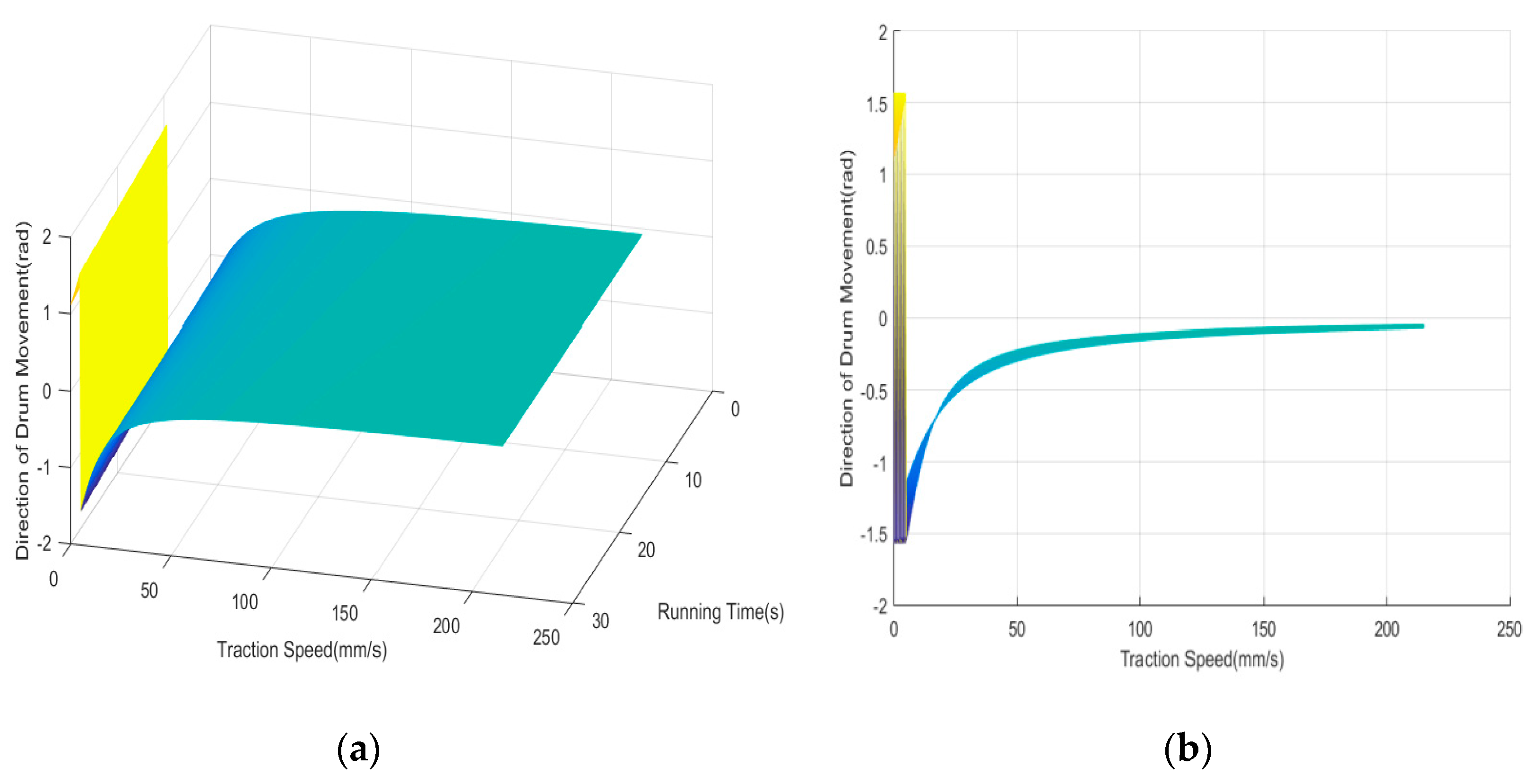
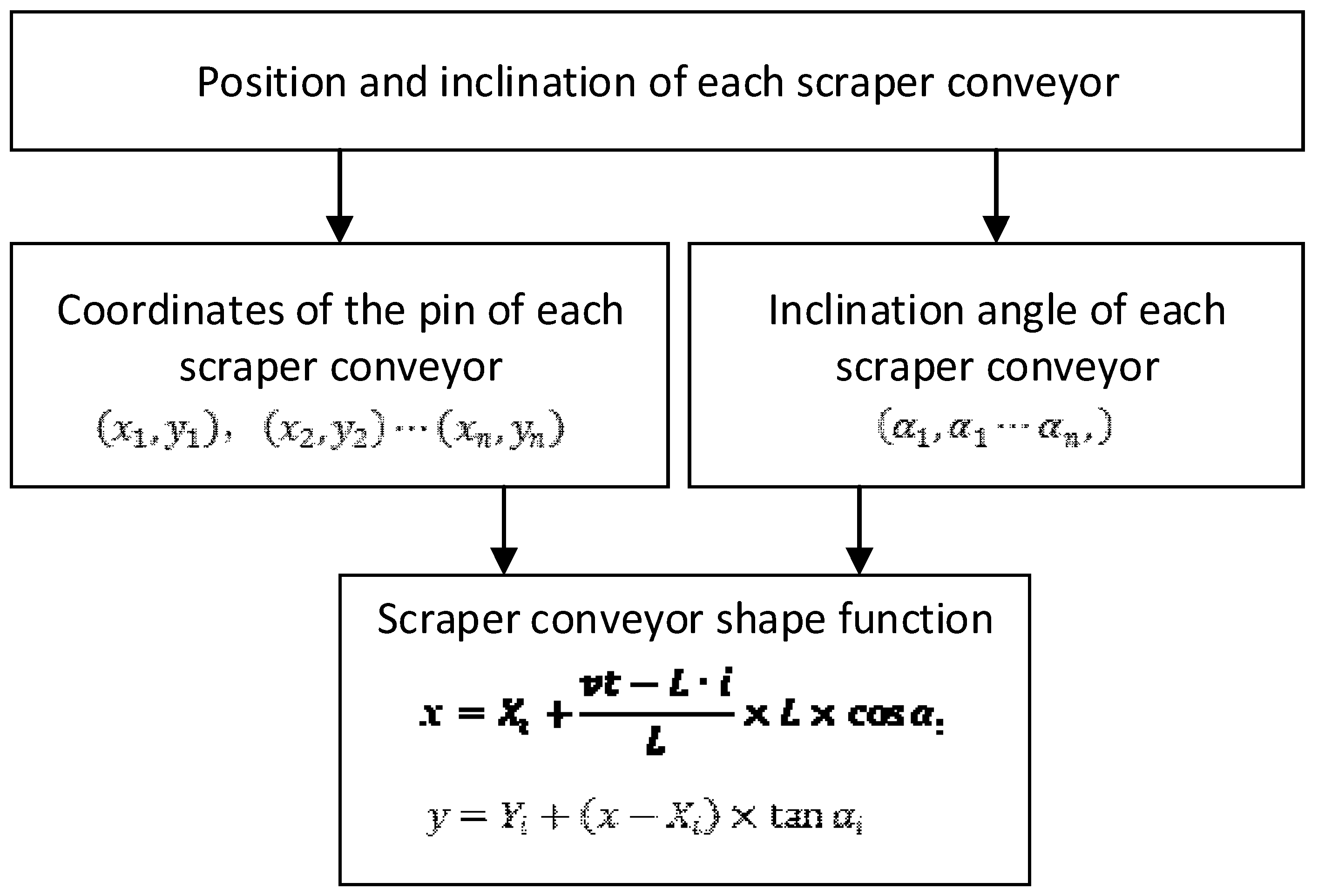
4.2. Key Technology for Combined Operation of Shearer and Scraper Conveyor

This paper presents a method of combined operation of the shearer and scraper conveyor on the real terrain of Unity3D.
The collider component in Unity3D provides a physical collision between the colliding bodies under gravity. Based on the above-mentioned modeling of coal seam, the mesh collider component is added to the GameObject of the coal seam floor and scraper conveyor to measure the position and the inclination of each scraper conveyor on the floor. Using the measured parameters of each scraper conveyor, they are arranged according to the actual arrangement rules. In the course of the shearer walking on the scraper conveyor, the attitude of its fuselage is determined by the left and right supporting slippers. Therefore, it is necessary to obtain the shape function of the scraper conveyor so that the slippers can move strictly along the obtained shape while the virtual walking of the shearer is controlled by coordinates. The shape function of the scraper conveyor can be calculated as shown in Figure 8.
Where ( X i , Y i ) is the coordinate of the pin of the ith scraper conveyor, mm; α i is the inclination angle of the ith scraper conveyor, rad; i is the serial number of the scraper conveyor where the slipper of the shearer is located; L is the length of a scraper conveyor, mm; v is the traction speed of the shearer, mm/s; t is the walking time of the shearer, s; x and y are the corresponding coordinate values on the shape function.
The ultimate effect in Unity3D is as shown in Figure 9:

4.3. Key Technology of Virtual Cutting of Shearer

In the Hierarchy interface of Unity3D, the hierarchical relationship (parent-child relationship) of each component is established. By defining the Transform property of each component through C# script, the parameters such as position, rotation, and size of each component can be obtained and varied through the script. The virtual shearer can be controlled by a programmed C# script based on the collaborative mathematical model, obtaining the start and stop, variable speed walking, positioning of the shearer, expansion, and rotation of the cylinder, adjustment of the drum height, and rotation of the drum. The components are moved using the 3D coordinate, whereas, they are rotated by the quaternion. The parent-child relationship of shearer components is shown in Figure 10.
In the process of creating a coal seam roof and floor, the cutting point data was stored as an XML file. As the shearer runs, the current number of the cutting feed is i , and the cutting point number within the range of one knife is j . The key cut point of the path in the entire coal seam is therefore, the set P i j ( i = 1 , 2 , 3 , j = 1 , 2 , 3 ) . When the system starts to run, the current cutting point of the working face can be read and the LineRender component in Unity3D is used to draw the curve of the coal roof and the cutting curve from time to time. The cut point data on the cut curve is also stored in the XML file for subsequent analysis of the simulation results. The schematic diagram of the cut point and the effect obtained in Unity3D are shown in Figure 11a,b, respectively.

5. Simulation Experiment

5.1. Setting of Simulation Conditions

Two different height-adjusting modes were designed in the experiment, namely; the automatic height-adjusting mode and the manual operation mode. In the planning stage of the fully mechanized mining face, the production capacity of the working face is often verified. In this study, the influence of shearer traction speed on production capacity was considered most. The lowest traction speed of the cutting process was set to ensure that the production capacity meets the requirements of different working faces. The feasible range of the haulage speed of the shearer was 2.5–12.9 m/min, 3.5–12.9 m/min, 4.5–12.9 m/min, and 0–12.9 m/min (operated by experienced workers).

5.2. Analysis of Simulation Results

In scheme 1, the actual cutting curve coincides with the preset roof curve, and the maximum error was obtained to be 12 cm. However, in schemes 2 and 3, an increase in the minimum traction speed of shearer decreased the coincidence, and the maximum error was obtained to be 48 cm. This could be attributed to the fact that the direction of the drum movement cannot meet the changing trend of the preset roof curve when the shearer is at the minimum traction speed. During the height-adjusting of the shearer while walking, if the shearer is running at a relatively large traction speed, K (the angle of the direction of drum movement) is relatively small, and the drum height-adjusting cannot be performed in a large scale. At the position where the roof and floor of the coal seam fluctuates greatly, the cutting curve will produce a large error. The effect in Unity3D is shown in Figure 12a and the cutting errors of the four schemes are shown in Figure 12b.
In production, scientific research and our daily life, we need to evaluate the quality of goods, the reasonable degree of some engineering design parameters, etc. to determine the best way to deal with them. In the cutting process of the fully mechanized mining face, there are many indexes to measure the quality of the cutting results, including the coal quality, recovery rate, production efficiency, economic benefit, and safety degree. Evaluating coal production is not an easy task, as it involves dimensionless index, human decision making, which are imprecise, fuzzy, and uncertain. Hence, using a scientific method to evaluate coal production comprehensively and effectively plays a crucial role in the analysis of simulation results.
The evaluation that needs to be made according to many factors is called comprehensive evaluation. When some specific evaluation factors are fuzzy, the comprehensive evaluation is called a fuzzy comprehensive evaluation. The fuzzy theory bridges the gap between the precise classical mathematics and the fuzzy real world. Fuzzy comprehensive evaluation method is a method which transforms qualitative evaluations into quantitative evaluations through the membership degree theory of fuzzy mathematics. It, therefore, has a good theoretical basis for the overall evaluation of things or objects having many constraints. Hence, the fuzzy comprehensive evaluation method is suitable for evaluating the cutting results. The general steps of fuzzy comprehensive evaluation include the construction of evaluation indexes, the determination of the weight of each index, the construction of the evaluation matrix, the synthesis of evaluation matrix and weight.
The specific steps for evaluating the cutting results using the fuzzy comprehensive evaluation are as follows:
• Determine the evaluation object
X = { x 1 , x 2 , x 3 , x 4 } = { scheme 1 , scheme 2 , scheme 3 , scheme 4 } .
• Determine the index set
U = { u 1 , u 2 , u 3 } = { recovery   rate ,   production   efficiency ,   others ( safety   degree ,   labor   cos t ,   etc )   } .
When the index set is determined, each of the indicators of each scheme is analyzed quantitatively. The recovery rate is expressed by the sum of the squares due to the error of the cutting points thus: S S E = i = 1 n w i ( y i y ) 2 , where y i   and   y are the heights of the actual cutting point and the preset roof point, respectively. The efficiency of production is represented by the time used for cutting one knife, however, other factors are scored according to the production experience of the general enterprises (0−9 point). The scores of each index are shown in Table 2.
• Determine the weight vector of the evaluation index
Set the weight vector to A = ( W 1 , W 2 W n ) , where W i indicates the i -th index weight coefficient. The matrix gives different weights to each index according to the different functions of each index in the overall evaluation. Under the condition that the safety level and other production costs are guaranteed, coal production pays more attention to the production efficiency directly linked to economic benefits and the recovery rate that can maximize the use of resources. According to the general enterprise production experience [24], A = ( 0.4 ,   0.4 ,   0.2 ) .
• Determine the fuzzy evaluation matrix
After determining the weights of the indicators, the evaluation index needs to be normalized and quantified one by one. A row in the fuzzy evaluation matrix R reflects the degree of membership of different schemes on this indicator. For the evaluation index with a specific value, the value of the optimal evaluation object can be set to 1 whereas, it is set according to the scoring level (0 ≤ E ≤ 1) for other objects. For the index whose value is bigger and whose evaluation is better, the calculation method of evaluation value is: Evaluation value = specific value/optimal value. For the index whose value is smaller and whose evaluation is better, the calculation method of evaluation value is: Evaluation value = optimal value/specific value. When calculating the evaluation value of the recovery rate, a higher SSE indicates a lower recovery rate, and the evaluation value should be smaller. Among the four schemes, the one with the highest recovery rate is scheme 1, and the corresponding SSE value is 13.89. Then, the evaluation value of scheme 1 is set to 1, the evaluation value of scheme 2 is set to 0.15 = 13.89 92.5 , the evaluation value of scheme 3 is set to 0.11 = 13.89 125.73 , the evaluation value of scheme 4 is set to 0.339 = 13.89 40.96 .
Finally, the fuzzy evaluation matrix is obtained thus:
R = [ 1 0.15 0.11 0.339 0.7 0.808 1 0.646 1 1 1 0.25 ] .
• Comprehensive evaluation
Comprehensive fuzzy evaluation vector B is calculated by the combination of the fuzzy multiplication and fuzzy evaluation matrix R ;   B = A R . The common fuzzy multiplications mainly include single-factor prominent type and weighted average type, in order to be able to objectively evaluate the impact of each index, the fuzzy multiplication chosen in this paper is the weighted average method [25]; M (   · ,   v ) ,     b j =   ( a i · r i j ) ( j = 1 , 2 m ) . Hence, the final evaluation was calculated as follows:
B = A R
= [ 0.88 0.5832 0.644 0.444 ]
It can be observed that the four schemes above are sorted as schemes 1, 3, 4, and 2. The higher value of the test has a better comprehensive evaluation. When the minimum traction speed of the shearer is small, more accurate trajectory tracking can be achieved. With an increase in the minimum traction speed, the production efficiency of the shearer improves, whereas the accuracy of trajectory tracking decreases. On this basis, according to the requirements of different enterprises, the production process of different working parameters can be previewed and evaluated in a virtual environment.

6. Conclusions

Based on the motion analysis of the shearer and drum-height adjustment, and with the drum movement law as the judgment knowledge, an automatic height-adjusting strategy of shearer was designed in the Unity3D engine, which integrates the information of the roof and floor fluctuation, coal seam inclination, and shearer fuselage inclination.
The modeling of the roof and floor was accomplished in the Unity3D engine using the mesh and LineRender components. The key cutting points could be read and the actual cutting curve drawn.
A real shearer height-adjusting model was developed, which can be controlled by the c# script. By measuring the position and posture of the scraper conveyor on real terrain, and constructing the shape function of the scraper conveyor, the combined operation of the shearer and scraper conveyor was established. This provides theoretical support for shearer simulation on real terrain.
A conceptual idea is put forward: on the basis of geological exploration of coal seam, a virtual fine 3D coal seam is established. According to the production requirements of different enterprises, the pre-selected schemes and the decision-making are previewed in Unity3D, hence, digitized and visualized planning is carried out ahead of time. The entire production process can, therefore, be synchronously mapped in the production process, so as to obtain safe and efficient transparent mining.

Author Contributions

All authors (J.L.;Y.L.;J.X.;X.W.;X.G.) designed the project and participated in the experiments and the interpretation of the results. Conceptualization, J.L. and Y.L.; methodology, J.L.; software, J.X.; writing—original draft preparation, J.L.; writing—review and editing, J.L. and Y.L. All authors have read and agreed to the published version of the manuscript.

Funding

This work was supported by the Shanxi Province Nature Science Fund (201901D111056), the Shanxi province graduate education reform research topic (2019JG047), China Postdoctoral Science Foundation (No.2019M651081), and the Shanxi Youth Science and Technology Research Fund Project (201901D211022).

Conflicts of Interest

The authors declare no conflict of interest.

References

  1. Ralston, J.C.; Hargrave, C.O.; Dunn, M.T. Longwall automation: Trend, challenges and opportunities. Int. J. Min. Sci. Technol. 2017, 27, 15–21. [Google Scholar] [CrossRef]
  2. Chad, O.H.; James, C.A.; Ralston, J.C. Infrastructure-based localization of automated coal mining equipment. Int. J. Coal Sci. Technol. 2017, 4, 252–264. [Google Scholar]
  3. Ottogalli, K.; Rosquete, D.; Amundarain, A.; Aguinaga, I. Flexible Framework to Model Industry 4.0 Processes for Virtual Simulators. Appl. Sci. 2019, 9, 4983. [Google Scholar] [CrossRef] [Green Version]
  4. Ralston, J.C.; Reid, D.C.; Dunn, M.T. Longwall automation: Delivering enabling technology to achieve safer and more productive underground mining. Int. J. Min. Sci. Technol. 2015, 25, 865–876. [Google Scholar] [CrossRef]
  5. Tibbett, A.E.; Greenberg, S.; Brazil, E. The use of virtual reality scientific visualization for investigation and exploration of block cave mining system data. In Proceedings of the Virtual Reality and Spatial Information Applications in the Mining Industry Conference, University of Pretoria, Pretoria, South Africa, 15–17 July 2015. [Google Scholar]
  6. Xie, J.C.; Yang, Z.J.; Wang, X.W. A Virtual Reality Collaborative Planning Simulator and its Method for Three Machines in a Fully Mechanized coal Mining Face. Arab. J. Sci. Eng. 2018, 43, 4835–4854. [Google Scholar] [CrossRef] [Green Version]
  7. Alam, K.M.; Saddik, A.E. C2PS: A Digital Twin Architecture Reference Model for the Cloud Based Cyber Physical System. IEEE Acess. 2017, 5, 2050–2062. [Google Scholar] [CrossRef]
  8. Stothard, P.; Squelch, A.; Stone, R.; Van Wyk, E.; Kizil, M. Taxonomy of interactive computer-based visualization systems and content for the mining industry—Part 2. Min. Technol. 2015, 124, 83–96. [Google Scholar] [CrossRef]
  9. Xie, J.C.; Wang, X.W.; Li, X. Research status and prospect of virtual reality technology in field of coal mine. Coal Sci. Technol. 2019, 47, 53–59. [Google Scholar]
  10. Tichon, J.; Burgesslimerick, R. A review of Virtual Reality as a medium for safety related training in Mining. J. Health Saf. Res. Pract. 2011, 3, 33–40. [Google Scholar]
  11. Zhang, L.L.; Tan, C.; Wang, Z.B.; Yang, X.F. Memory Cutting Path Optimization of the Shearer Based on Genetic Algorithm. Coal Eng. 2011, 2, 111–113. [Google Scholar]
  12. Liu, C.S.; Yang, Q. Simulation of shearer drum cutting with memory program controlling by fuzzy control. J. China Coal Soc. 2008, 7, 822–825. [Google Scholar]
  13. Si, L.; Wang, Z.B.; Liu, Y.W. Online Identification of Shearer Cutting State Using Infrared Thermal Images of Cutting Unit. Appl. Sci. 2018, 8, 1772. [Google Scholar] [CrossRef] [Green Version]
  14. Li, W.; Luo, C.M.; Yang, H.; Fan, Q.G. Memory cutting of adjacent coal seams based on a hidden Markov model. Arab. J. Geosci. 2014, 4, 5051–5060. [Google Scholar] [CrossRef]
  15. Gospodarczyk, P. Modeling and simulation of coal loading by cutting drum in flat seams. Arch. Min. Sci. 2016, 61, 365–379. [Google Scholar]
  16. Xu, J.; Wang, Z.B.; Tan, C. A Cutting Pattern Recognition Method for Shearers Based on Improved Ensemble Empirical Mode Decomposition and a Probabilistic Neural Network. Sensors 2015, 15, 27721–27737. [Google Scholar] [CrossRef] [PubMed] [Green Version]
  17. Lemon, A.M.; Jones, N.L. Building solid models from boreholes and user-defined cross-section. Comput. Geo-Inf. Sci. 2003, 29, 547–555. [Google Scholar] [CrossRef]
  18. Che, D.F.; Wu, L.X.; Chen, X.X. Modeling and visualizing methods for real 3D geosciences model based on amended generalized tri-prism(GTP). J. China Coal Soc. 2006, 31, 576–580. [Google Scholar]
  19. Michel, P.; Zhu, B.T. Knowledge-driven applications for geological modeling. J. Petrol. Sci. Eng. 2005, 47, 89–104. [Google Scholar]
  20. Tacher, L.; Pomian-srzednicki, I.; Parriaux, A. Geological uncertainties associated with 3D subsurface model. Comput. Geosci. 2006, 2, 212–221. [Google Scholar] [CrossRef]
  21. Chen, J.F.; Hsieh, H.N.; Do, Q.H. Evaluating teaching performance based on fuzzy AHP and comprehensive evaluation approach. Appl. Soft Comput. 2015, 28, 100–108. [Google Scholar] [CrossRef]
  22. Ko, Y.C. Application of Fuzzy Theory to the Evaluation Model of Product Assembly Design and Usability Operation Complexity. Appl. Sci. 2019, 9, 4055. [Google Scholar] [CrossRef] [Green Version]
  23. Wang, T.J. Research on Generalized Memory Cutting Technology of Thin Seam Shearer Based on Dynamic Fine Modeling; China University of mining and Technology (Beijing Campus): Beijing, China, 2003. [Google Scholar]
  24. Gao, C.Z.; Li, Y.Z.; Wang, T.L. Safety production evaluation of coal mine based on fuzzy comprehensive evaluation and AHP. Opencast Min. Technol. 2013, 11, 72–77. [Google Scholar]
  25. Mu, Y.Z.; Lu, Z.X.; Qiao, Y. A Comprehensive Evaluation Index System of Power Grid Security and Benefit Based on Multi-Operator Fuzzy Hierarchy Evaluation Method. Power System Technol. 2015, 1, 23–28. [Google Scholar]
Figure 1. Overall framework.
Applsci 10 00771 g001
Figure 2. Height-adjusting system of the drum shearer.
Applsci 10 00771 g002
Figure 3. Relationship between the direction of drum movement, running time and traction speed of the shearer: (a) oblique view; (b) Y–Z view.
Applsci 10 00771 g003
Figure 4. Automatic height-adjusting diagram.
Applsci 10 00771 g004
Figure 5. Algorithm of the main process of the virtual cutting of shearer.
Applsci 10 00771 g005
Figure 6. Rules for sorting triangular vertices in roof and floor mesh: (a,c) connection order of triangle vertices; (b) clockwise and counterclockwise connections.
Applsci 10 00771 g006
Figure 7. Mesh of virtual coal seam roof and floor.
Applsci 10 00771 g007
Figure 8. Shape function of the scraper conveyor.
Applsci 10 00771 g008
Figure 9. Effect diagram of combined operation of shearer and scraper conveyor.
Applsci 10 00771 g009
Figure 10. Parent–child relationship of shearer components.
Applsci 10 00771 g010
Figure 11. Schematic diagram: (a) the map of cutting points (b) the effect of cutting points in Unity3D.
Applsci 10 00771 g011
Figure 12. Simulation results: (a) three-dimensional graph of cutting curve (b) error of the actual cutting points and the preset points.
Applsci 10 00771 g012
Table 1. Strategy of action judgment.
Judgment of ActionBefore AdjustmentSpecific ActionAfter Adjustment
Δ H > Δ H m a x or Δ H < Δ H m i n Too high or too low Traction speed is reduced to a minimum, drum lifts
Δ H < Δ H m a x and Δ H > Δ H u p LiftingK-Q > 0.02Traction speed is increased, drum lifts|Q-K| ≤ 0.02
Q-K > 0.02Traction speed is decreased, drum lifts
|Q-K| ≤ 0.02Traction speed is decreased, drum lifts
Δ H < Δ H u p and Δ H > Δ H d o w n No adjustment Traction speed is constant, drum is not adjusted
Δ H < Δ H d o w n and Δ H > Δ H m i n DescendingK-Q > 0.02Traction speed is increased, drum descends|Q-K| ≤ 0.02
Q-K > 0.02Traction speed is decreased, drum descends
|Q-K| ≤ 0.02Traction speed is constant, drum descends
Table 2. Evaluation index.
IndexRecovery Rate (SSE)Production Efficiency (min)Others (Safety Degree, Labor Cost, etc.)
Scheme113.8988
Scheme292.578
Scheme3125.735.58
Scheme440.968.52

