Article

Seismic Response Mitigation of Base-Isolated Buildings

by
Mohammad Hamayoun Stanikzai
1,
Said Elias
2,* and
Rajesh Rupakhety
2
1
Department of Civil and Environmental Engineering, Old Dominion University, Norfolk, VA 23529, USA
2
Earthquake Engineering Research Centre, Faculty of Civil and Environmental Engineering, School of Engineering and Natural Sciences, University of Iceland, Austurvegur 2a, 800 Selfoss, Iceland
*
Author to whom correspondence should be addressed.
Appl. Sci. 2020, 10(4), 1230; https://doi.org/10.3390/app10041230
Submission received: 30 December 2019 / Revised: 31 January 2020 / Accepted: 6 February 2020 / Published: 12 February 2020

Abstract

:
Earthquake response mitigation of a base-isolated (BI) building equipped with (i) a single tuned mass damper at the top of the building, (ii) multiple tuned mass dampers (MTMDs) at the top of the building, and (iii) MTMDs distributed on different floors of the building (d-MTMDs) is studied. The shear-type buildings are modeled by considering only one lateral degree of freedom (DOF) at the floor level. Numerical approach of Newmark’s integration is adopted for solving the coupled, governing differential equations of motion of 5- and 10-story BI buildings with and without TMD schemes. A set of 40 earthquake ground motions, scaled 80 times to get 3200 ground motions, is used to develop simplified fragility curves in terms of the isolator maximum displacement. Incremental dynamic analysis (IDA) is used to develop simplified fragility curves for the maximum target isolator displacement. It is found that TMDs are efficient in reducing the bearing displacement, top floor acceleration, and base shear of the BI buildings. In addition, it was noticed that TMDs are efficient in reducing the probability of failure of BI building. Further, it is found that the MTMDs placed at the top floor and d-MTMDs on different floors of BI buildings are more efficient in decreasing the probability of failure of the BI building when compared with STMD.

1. Introduction

Over the last couple of decades, structural vibration control techniques have been popularized for mitigation of dynamic response caused by various environmental actions. Tuned mass dampers (TMDs) are one of the common control methods used for response mitigation of structures under dynamic loadings. Their applications in various situations and loads have been addressed by several researchers [1,2,3,4,5,6,7]. As single tuned mass dampers (STMDs) became popular, a more practical solution, for example, by distributing TMD mass over the structure is being investigated in recent times [8,9,10,11,12,13,14,15,16]. A detailed literature survey on passive TMDs is presented in Elias and Matsagar [17].
Base-isolation (BI) has been one of the most popular and well-established method of seismic response control. This method makes use of special devices such as friction pendulum, lead rubber bearings, etc, to isolate the main structure from the shaking of the ground. Base-isolation system works by making the isolated structure more flexible at the base, thereby reducing acceleration response of the superstructure and therefore base shear force on the structure. As a consequence of added flexibility, displacement demand on the structure gets amplified, and additional damping is provided to keep displacement demand within acceptable limits. Zelleke et al. [18] studied the effectiveness of viscous and visco-elastic dampers on seismic response control of BI buildings. They found that there is a tradeoff between the extent to which acceleration and displacement demand can be controlled by BI system combined with additional damping devices.
Tsai [19] investigated the use of TMD alongside BI and observed that TMD is efficient in response mitigation of BI systems if the dominant period of excitation is longer than the natural period of the structure. Yang et al. [20] studied the efficiency of passive TMDs in response control of BI buildings. Xiang and Nishitani [21] described the effectiveness of optimally designed non-traditional TMD for mitigation of seismic response of BI buildings. Use of TMD with inerter (TMDi) was proposed by De Domenico et al. [22] and De Domenico and Ricciardi [23,24,25] for diminishing response of BI buildings under earthquakes. Rabiee and Chae [26] reported the effectiveness of MR dampers for response mitigation of BI building under short and long period ground motions. Effectiveness of single TMD (STMD), multiple TMDs (MTMDs), and distributed MTMDs (d-MTMD) on seismic response control of BI buildings was investigated by Stanikzai et al. [27,28]. They noticed that d-MTMDs were more efficient and practical than other schemes.
Past studies on efficiency of TMDs in response mitigation of BI buildings have relied on a limited number of earthquake ground motions. As there is a large uncertainty in the frequency content, amplitude, and duration of ground shaking a structure can experience, a control scheme that is found effective for a certain type of ground motion may not be effective for other ground motions. It is therefore necessary to consider these uncertainties to have a robust understanding of the usefulness of TMDs in response mitigation of BI structures. Therefore, a probabilistic approach, for example, an examination of fragility curves of structures with and without the TMDs, can shed more light on the overall benefits of using TMDs in BI structures. Such analysis of BI buildings equipped with TMDs is lacking in the literature.
Among many other methods, the incremental dynamic analysis (IDA) is one of the popular methods of estimating analytical fragility curves of structures. The idea of incremental dynamic analysis (IDA) was introduced by Bertero [29]. Kennedy et al. [30] proposed the concept of fragility analysis in the field of earthquake engineering. Later, the idea was extended by many researchers including Bazzurro and Cornell [31,32] and Luco and Cornell [33,34]. This method of fragility analysis was further expanded by Vamvatsikos and Cornell [35]. Nowadays, it is broadly employed in seismic risk evaluation of structures. The IDA has been taken by the U.S. Federal Emergency Management Agency (FEMA, [36,37]) standards as a state-of-the-art technique to verify the global collapse capacity of structures. The IDA relies on nonlinear structural analysis using ground motions with increasing intensity, estimating some damage measure (DM) for each ground motion, which is characterized by an intensity measure (IM). Different IMs, for example, peak ground velocity (PGV), peak ground acceleration (PGA), spectral acceleration, etc., can be used to characterize ground motions. Damage measures are related to response parameters such as peak base shear, joint rotation, peak story drift, and bearing displacement. Probabilities of exceeding a specified damage measure for a given excitation intensity level can be estimated if IDA is conducted with an adequate number of ground motions.
This study applies IDA method to estimate seismic fragility of buildings with BI systems and investigates the extent to which such fragility can be reduced using different TMD schemes.

2. Structural Model

Schematic representation of different structures considered here is presented in Figure 1. An idealized N-story BI building is demonstrated in Figure 1a. The masses are lumped at the floor levels, and the floors are deemed to act as a rigid diaphragm. One horizontal translational degree of freedom (DOF) is assigned to each floor. BI structures with different control schemes are shown in Figure 1a–d. In Figure 1b, a TMD is placed at the nth floor, and this scheme is called as BI + STMD. In Figure 1c, MTMDs are placed at the nth floor, and the scheme is called as BI + MTMDs. When the multiple TMDs are placed on various floors, as displayed schematically in Figure 1d, the scheme is called BI + d-MTMDs. For the sake of simplicity, the superstructure is presumed to remain linearly elastic and soil structure interaction (SSI) is not considered.
The governing equation of motion of the system under ground shaking can be written as
[ M ] { x ¨ ( t ) } + [ C ] { x ˙ ( t ) } + [ K ] { x ( t ) } = [ M ] { r } { x ¨ g }
where [ M ] is the mass matrix; [ C ] is the damping matrix and [ K ] is the stiffness matrix of the structure; { x } = { X 1 , X 2 , X N , X b , x T 1 , x T 2 , x T n } T , x ˙   , and x ¨ are the unknown relative (floor, isolator, and TMD) displacement, velocity, and acceleration vectors, respectively; { x ¨ g } is earthquake ground acceleration; and { r } is the vector of influence coefficients. Following Stanikzai et al. [28], the [ M ] , [ C ] , and [ K ] matrices of the BI buildings installed with TMDs can be written as
[ M ] = [ [ m b ] 1 × 1 [ M N ] 1 × N [ m n ] 1 × n [ M N ] N × 1 [ M N ] N × N [ 0 ] N × n [ m n ] n × 1 [ 0 ] n × N [ m n ] n × n ]
[ C ] = [ [ c b ] 1 × 1 [ 0 ] 1 × N [ 0 ] 1 × n [ 0 ] N × 1 [ C N ] N × N + [ c n ] N × N [ c n ] N × n [ 0 ] n × 1 [ c n ] n × N [ c n ] n × n ]
[ K ] = [ [ k b ] 1 × 1 [ 0 ] 1 × N [ 0 ] 1 × n [ 0 ] N × 1 [ K N ] N × N + [ k n ] N × N [ k n ] N × n [ 0 ] n × 1 [ k n ] n × N [ k n ] n × n ]
where [mb] is isolator mass matrix, [MN] is superstructure mass matrix, and [mn] is the TMDs schemes mass matrix. [cb], [CN], and [cn] are the corresponding damping matrices. Similarly, [kb] is isolator stiffness matrix, [KN] is superstructure stiffness matrix, and [kn] is the TMDs schemes stiffness matrix. The N story building is isolated by one DOF isolator and equipped by n number of TMDs, that results in the matrices of the order (N + n + 1) × (N + n + 1).

3. Mathematical Model of Isolator

In this study, a lead rubber bearing (N-Z) isolator is considered. Wen’s model (Wen, [38]) is used for characterization of hysteretic behavior of the bearing. Figure 2a shows schematic representation of lead rubber bearings. The restoring force developed in the isolation is given by
F b = c b x ˙ b + α k b x b + ( 1 α )   F y Z
where the yield strength of the bearing is denoted by F y , initial stiffness of the bearing is denoted by k b , and viscous damping of the bearing is denoted by c b ; α signifies the ratio of post- to pre-yielding stiffness. A non-dimensional hysteretic displacement component is denoted by Z, which satisfies the following non-linear first order differential equation
q Z ˙ = A x ˙ b + β | x ˙ b | | Z | Z | n k 1 + τ x ˙ b | Z | n k
where the yield displacement is denoted by q; A,   β , τ, and nk are dimensionless model parameters, often calibrated from experimental tests. The integer parameter nk controls the smoothness of transition from elastic to plastic deformation. The isolation period (Tb), damping ratio ( ξ b ) , and normalized yield strength characterizes the N-Z isolation system. Using the post-yielding stiffness (kp) of the bearing, the isolation period (Tb) and damping ratio ( ξ b ) are computed by Equations (7) and (8), respectively.
T b = 2 π M k p
ξ b = c b 2 M ω b
where ω b is the isolator frequency and W = M g   is the total weight of the building plus isolator and TMDs, and g is the acceleration due to gravity. Other parameters are maintained constant with q = 2.5   cm , β = τ = 0.5 , A = 1 , and n = 2 .

4. Mathematical Model of the TMD

Figure 2b shows schematic illustration of a TMD, which is made up of a mass attached to the floor by a spring and a dashpot. The ith TMD is illustrated by its stiffness ( k i ), damping constant ( c i ), and the mass ( m i ). The TMD’s mass ratio μ , designed frequency ω i , tuning frequency ratio f , and damping ratio ξ i , are given by
ω i = k i m i
ξ i = c i 2   ω i m i
f i = ω i ω b
μ i = m i m s
where m s represents total mass of the BI building. The proposed formulas by Sadek et al. [39] for optimum tuning frequency ratio f S T M D = 1 1 + μ S T M D [ 1 ξ b μ S T M D 1 + μ S T M D   ] and damping ratio ξ S T M D =   ξ b 1 + μ S T M D + μ S T M D 1 + μ S T M D are considered for STMD.
Figure 1c–d show the main system equipped with n number of TMDs (MTMDs) with various dynamic characteristics. The BI system and each TMD is modeled with a single DOF. In this study, MTMDs and d-MTMDs are designed by considering unequal masses. The designed frequency of ith TMD is stated as
ω i = ω T [ 1 + ( i n + 1 2 ) β n 1 ]
where ω T is the average frequency of all the MTMDs (i.e., ω T = j = 1 n ω j / n ). Based on the recommendation of De Domenico and Ricciardi [25], the average frequency is taken as 0.78 times the fundamental frequency of the BI building. Non-dimensional frequency spacing parameter β   of the MTMDs is defined as
β = ω n ω 1 ω T
For a set of TMD units with equal stiffness (i.e., k 1 = k 2 = k 3 = = k n ) and equal damping ratio (i.e., ξ 1 = ξ 2 = ξ 3 = = ξ n ), the stiffness ( k j ) is calculated as
k j = m n ( 1 / ω 1 2 + 1 / ω 2 2 + + 1 / ω n 2 )
where m n is the total mass of all the TMD(s), and the mass of the ith TMD ( m i ) is given by
m i = k i ω i 2
and the damping coefficient of the TMDs is then given by
c i = 2 ξ i m i ω i
In this study, n = 3 is assumed for the cases of MTMDs and d-MTMDs; for MTMDs cases, all the TMDs are placed at the top floor, whereas for d-MTMDs, the TMDs are placed at the top three floors.

5. Numerical Study

Numerical study is conducted on response mitigation of 5- and 10-story BI buildings equipped with TMDs at top and at different floor levels under earthquake ground motions. The shear-type buildings are modeled by considering only a lateral DOF at each floor level. The coupled governing differential equation of motion for the system is formulated and solved using Newmark’s integration method with linear acceleration assumption between consecutive time steps. For the sake of simplicity, the floor mass and stiffness are kept the same herein. The structural damping matrix is constructed by assuming 2% damping ratio in all the normal modes of vibration. The isolation period and the TMDs mass ratio are assumed to be 2.5 s and 5%, respectively. The total TMD mass is then divided into three TMDs for the cases of MTMDs and d-MTMDs. In addition, the isolation damping ratio, yield displacement, and normalized yield strength (yield strength per unit weight of the structure) are assumed to be 0.05, 5 cm, and 0.05, respectively [40]. The 5- and 10-story buildings have 0.5 s and 1 s fundamental period, respectively, when they are fixed at the base.
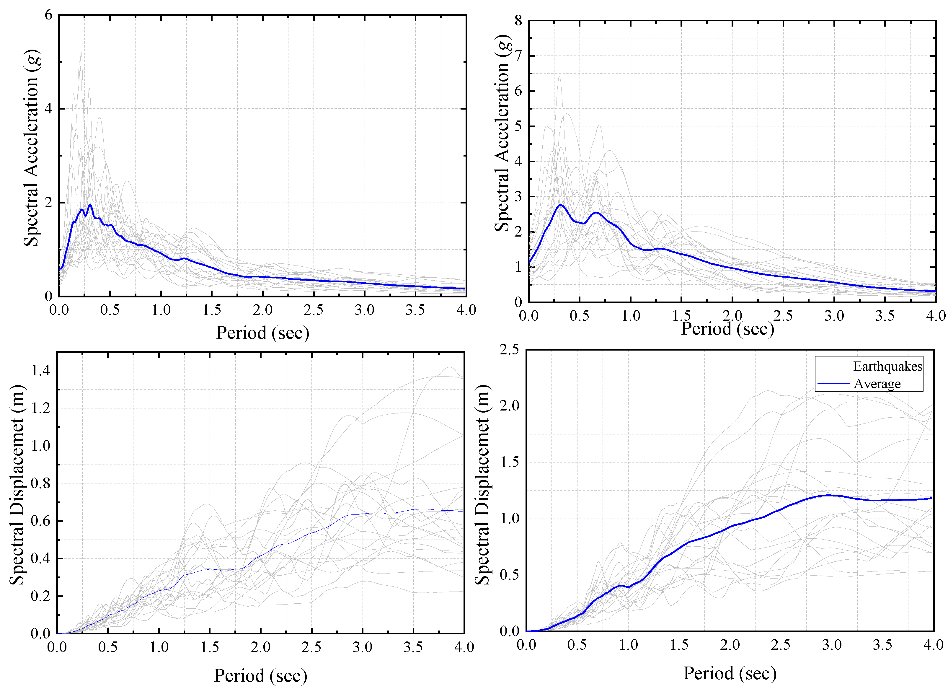
Incremental dynamic analysis (IDA) of the above-mentioned buildings is conducted. A set of 40 earthquake ground motions are considered (see Table 1 and Table 2). Somerville et al. [41] provide more details of the set of 40 ground motions for a theoretical site in Los Angeles, USA. The set is divided into two categories: (1) design-basis earthquakes (DBE) and (2) maximum considered earthquakes (MCE). The DBE are listed as LA01 to LA20 and the MCE are listed as LA21 to LA40 in Table 1 and Table 2, respectively. In order to better understand the nature of the selected DBE and MCE earthquake ground motions, their displacement and acceleration response spectra considering 2% critical damping are shown in Figure 3. It can be seen that that selected list encompasses a wide range of amplitude and frequency content of ground shaking. Each ground motion in the set of 40 are scaled to PGA of 0.025 to 2 g with an increment of 0.025 g (80 times). As a result, a set of 3200 ground motions are obtained, which are used for IDA. Numerical simulation is carried out with MATLAB. The earthquake ground excitations are scaled based on the procedure given in Bhandari et al. [42].

5.1. Performance of TMDs in Response Mitigation

Figure 4 illustrates the time history and Fourier Amplitude Spectra (FAS) of top floor acceleration and bearing displacement of BI and BI equipped by different TMD schemes under LA04 earthquake ground motion. It is observed that the BI building has relatively low acceleration at the top of building, but very large bearing displacement. The TMDs effectively reduce this large displacement demand. The peak bearing displacement of BI, BI + STMD, BI + MTMDs, and d-MTMDs are, respectively, 1.86 m, 1.5 m, 1.18, and 1.12 m. It is observed that the STMD could reduce the displacement by about 20%, whereas, MTMDs and d-MTMDs could reduce displacement by up to 40%. It is also evident that this reduction in bearing displacement is not at the cost of amplified acceleration.
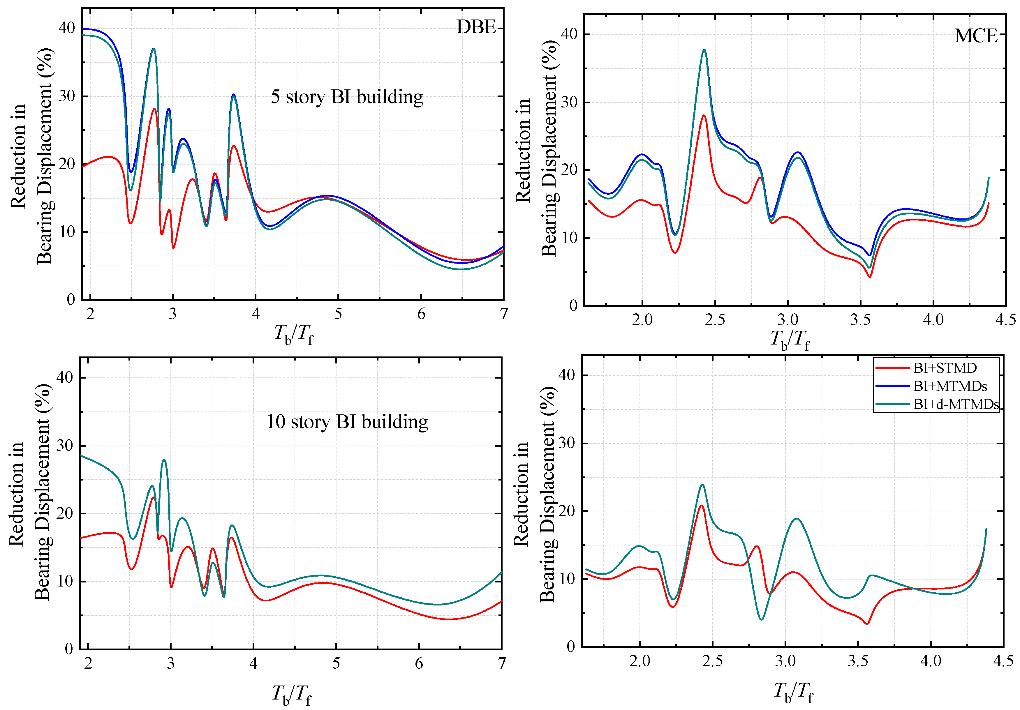
Thereafter, efficacy of the STMD, MTMDs, and d-MTMDs in vibration mitigation of 5- and 10-story BI buildings under DBE and MCE earthquakes are presented in Figure 5 and Figure 6. To identify the reason for effectiveness or vice versa, response of each scheme is arranged based on ratio of Tb/Tf, where Tb is the isolation period and Tf is the dominant period of ground motion [43,44]. The TMD schemes are found to be more effective in controlling displacement response when the isolation period is less than about 3 times the dominant period of ground motion. The d-MTMDs showed marginally more effectiveness for 5-story BI building (see Figure 5). Even if the d-MTMDs show performance similar to STMD and MTMDs, it would be more practical as the TMDs are distributed on different floors, which is better than placing a large mass at the top of the structure. It is to be noted that for acceleration control, all TMD schemes are similar except in few cases. In most cases, MTMDs and d-MTMDs provide higher reduction in displacement. However, STMD showed a superior performance for acceleration response control (see Figure 5 and Figure 6). Overall, the TMD schemes are more effective in controlling response of the 5-story BI building. Hence, it is determined that TMD schemes are effective in reducing response of BI buildings under DBE earthquake excitations, especially when Tb/Tf     3.

5.2. Seismic Effectiveness of Hybrid System

Probability distribution functions of the BI buildings with and without TMD schemes are presented in this section. Assuming a lognormal model, the probability distribution of bearing displacement, top floor acceleration, and normalized base shear are estimated form the calculated response. Cumulative distribution function (CDF) of response quantities of BI buildings with and without TMD schemes are presented in Figure 7 and Figure 8. Figure 7 shows that the use of TMDs in BI buildings is more effective in mitigation of displacement response than acceleration response and base shear demand. In addition, MTMDs and d-MTMDs are only marginally better than STMDs. Overall, TMDs are found to be effective in decreasing the seismic response (bearing displacement and top floor acceleration) of 5-story BI building. It is noticed that the trend of reduction in displacement and acceleration of the 10-storey building is almost the same (see Figure 8) as that of the 5-story building, but the TMD devices are less effective.

5.3. Seismic Fragility Analysis

Seismic fragility is defined as the probability of exceeding a defined damage state due to a given seismic intensity measure (IM). It happens when the seismic applied load (demand) is greater than the structural capacity. Seismic fragility can be expresses as,
Fragility   P [ Demand > Capacity ]
For the fragility analysis of the buildings, following two steps are considered: (1) A failure criteria is defined and (2) a set of seismic intensity measures are selected. Here, the failure criterion is considered as maximum isolator displacement, which ensures the safety of isolation system. In this study, the collapse state of damage is based on limit states proposed by Bhandari et al. (2018). They proposed a limit state for isolator displacement for elastic, elastic–plastic, and plastic states. The maximum target displacement assuming the plastic state is considered 330 mm in this study. Once the target displacement is specified, the analysis of BI buildings equipped with different TMD schemes using the set of 40 earthquakes, each scaled 80 times is carried out. The peak absolute isolator displacement is recorded. The recorded peak response of the BI building with and without TMD schemes for the generated number of ground motions ( N gen ) are then compared with the corresponding seismic demands. Thereafter, the probability of failure P f at any certain PGA level is defined as following
P f = N fail N gen
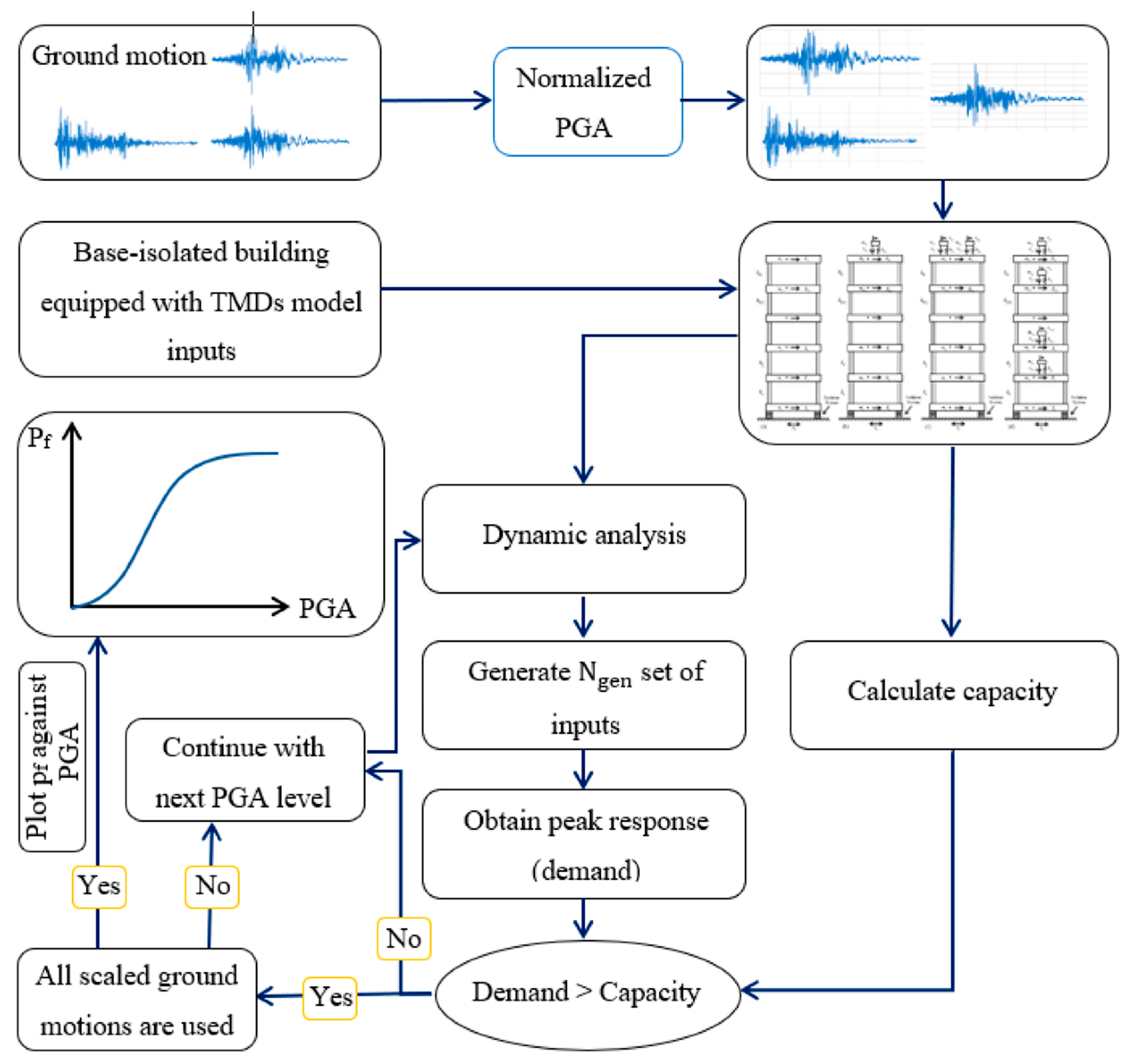
where N fail denotes the number of the cases which satisfies Equation (18). Then the process is reiterated for the range of the above-mentioned PGA levels, and the respective fragility curves are achieved assuming a lognormal distribution. The procedure of obtaining the fragility curves for the BI building equipped with the TMD schemes is schematically described in Figure 9. The bearing displacement fragility curves for 5-story BI building equipped with TMDs is depicted in Figure 10.
The TMD schemes reduce the probability of the considered damage state by about 10% across a range of PGA. The MTMDs and d-MTMDs are found to perform slightly better than the STMDs. In addition, similar trend of response reduction was observed for the case of 10-story BI building equipped with TMDs and the results are shown in Figure 11. Since these fragility curves represent uncertainty in ground motion intensity and frequency content, while the structure is assumed to be deterministic, the resulting fragility curves are called as simplified fragility curves in the sense that they might be different from real fragilities of a structure with uncertain parameters. There is future scope for experimental verification of the concept like reference [45].

6. Conclusions

Seismic response mitigation of base-isolated (BI) building installed with a single tuned mass damper (STMD), multiple TMDs (MTMDs), and distributed MTMDs (d-MTMDs) are investigated. Numerical analysis of two BI buildings equipped with TMDs is performed using analytical models of 5- and 10-storey buildings. Results were analyzed to investigate effectiveness of different TMD schemes in reducing displacement and acceleration demand of the BI structure. Such effectiveness was investigated in terms of percentage reduction in response as a function of ground motion frequency content, probability distribution functions of response parameters, and fragility curves corresponding to failure of the isolation device due to excessive displacement. The following conclusions can be made from the results of the analyses.
  • TMD schemes are can be used to control bearing displacement of BI buildings subjected to earthquake ground excitations without compromising the control in acceleration response achieved by BI.
  • MTMDs and d-MTMDs are marginally better than STMD in controlling the bearing displacement of the BI building. The effectiveness of MTMDs and d-MTMDs are same as STMD for mitigating top floor acceleration.
  • The TMD schemes reduce the fragility of the structure by about 5% in a wide range of PGA of 0.5g to 1g. For weaker and stronger shaking, the reduction in fragility is not significant. It is to be noted that the TMDs used in this study are not optimized for specific type of ground motions and might experience detuning effects for some ground motions. Designing such TMDs based on effective period of vibration of a structure for a well-established target displacement obtained from appropriate hazard analysis might provide additional benefits.

Author Contributions

All authors discussed and agreed upon the idea, and made scientific contributions. M.H.S. coded the MATLAB program and wrote initial draft of the paper. S.E. and R.R. improved and revised the initial paper. All authors have read and agreed to the published version of the manuscript.

Funding

It was part of the employment activity no extra funds were given to this study.

Acknowledgments

Authors acknowledge the efforts of reviewers and editors for improving the quality of the paper. First author acknowledges the department of Civil and Environmental Engineering, Old Dominion University, for allowing him to use the work stations and space. Second and third authors acknowledge support from the University of Iceland Research Fund.

Conflicts of Interest

The authors declare no conflict of interest.

References

  1. Greco, R.; Marano, G.C. Optimum design of Tuned Mass Dampers by displacement and energy perspectives. Soil Dyn. Earthq. Eng. 2013, 49, 243–253. [Google Scholar] [CrossRef]
  2. Longarini, N.; Zucca, M. A chimney’s seismic assessment by a tuned mass damper. Eng. Struct. 2014, 79, 290–296. [Google Scholar] [CrossRef]
  3. Reggio, A.; Angelis, M.D. Optimal energy-based seismic design of non-conventional Tuned Mass Damper (TMD) implemented via inter-story isolation. Earthq. Eng. Struct. Dyn. 2015, 44, 1623–1642. [Google Scholar] [CrossRef]
  4. Lu, Z.; Li, K.; Zhou, Y. Comparative Studies on Structures with a Tuned Mass Damper and a Particle Damper. J. Aerosp. Eng. 2018, 31, 04018090. [Google Scholar] [CrossRef]
  5. Rezaee, M.; Aly, A.M. Vibration Control in Wind Turbines to Achieve De-sired System-Level Performance under Single and Multiple Hazard Loadings. Struct. Control Health Monit. 2018. [Google Scholar] [CrossRef]
  6. Wang, C.; Shi, W. Optimal Design and Application of a Multiple Tuned Mass Damper System for an In-Service Footbridge. Sustainability 2019, 11, 2801. [Google Scholar] [CrossRef] [Green Version]
  7. Cao, L.; Li, C. Tuned tandem mass dampers-Inerters with broadband high effectiveness for structures under white noise base excitations. Struct. Control Health Monit. 2019, 26, e2319. [Google Scholar] [CrossRef]
  8. Elias, S.; Matsagar, V.; Datta, T.K. Effectiveness of distributed tuned mass dampers for multi-mode control of chimney under earthquakes. Eng. Struct. 2016, 124, 1–16. [Google Scholar] [CrossRef]
  9. Elias, S.; Matsagar, V.; Datta, T.K. Distributed tuned mass dampers for multi-mode control of benchmark building under seismic excitations. J. Earthq. Eng. 2019, 23, 1137–1172. [Google Scholar] [CrossRef]
  10. Elias, S.; Matsagar, V.; Datta, T.K. Along-Wind response control of chimneys with distributed multiple tuned mass dampers. Struct. Control Health Monit. 2019, 26, e2275. [Google Scholar] [CrossRef] [Green Version]
  11. Elias, S.; Matsagar, V.; Datta, T.K. Dynamic response control of a wind-excited tall building with distributed multiple tuned mass dampers. Int. J. Struct. Stab. Dyn. 2019, 19, 1950059. [Google Scholar] [CrossRef]
  12. Gill, D.; Elias, S.; Steinbrecher, A.; Schröder, C.; Matsagar, V. Robustness of multi-mode control using tuned mass dampers for seismically excited structures. Bull. Earthq. Eng. 2017, 15, 5579–5603. [Google Scholar] [CrossRef]
  13. Elias, S. Seismic energy assessment of buildings with tuned vibration absorbers. Shock Vib. 2018, 2018. [Google Scholar] [CrossRef]
  14. Elias, S. Effect of SSI on vibration control of structures with tuned vibration absorbers. Shock Vib. 2019, 2019. [Google Scholar] [CrossRef] [Green Version]
  15. Elias, S.; Matsagar, V. Seismic vulnerability of non-linear building with distributed multiple tuned vibration absorbers. Struct. Infrastruct. Eng. 2019, 15. [Google Scholar] [CrossRef]
  16. Matin, A.; Elias, S.; Matsagar, V. Distributed multiple tuned mass dampers for seismic response control in bridges. Proc. Inst. Civ. Eng. Struct. Build. 2019, 1–18. [Google Scholar] [CrossRef]
  17. Elias, S.; Matsagar, V. Research developments in vibration control of structures using passive tuned mass dampers. Annu. Rev. Control 2017, 44, 129–156. [Google Scholar] [CrossRef]
  18. Zelleke, D.H.; Elias, S.; Matsagar, V.A.; Jain, A.K. Supplemental Dampers in Base-Isolated Buildings to Mitigate Large Isolator Displacement Under Earthquake Excitations. Bull. N. Z. Soc. Earthq. Eng. 2015, 48, 100–117. [Google Scholar] [CrossRef] [Green Version]
  19. Tsai, H. The Effect of Tuned-Mass Dampers on the Seismic Response of Base-Isolated Structures. Int. J. Solid Struct. 1995, 32, 1199–1210. [Google Scholar] [CrossRef]
  20. Yang, J.; Danielianns, A.; Liu, S. Aseismic Hybrid Control Systems for Building Structures. J. Eng. Mech. 1991, 117, 836–853. [Google Scholar] [CrossRef]
  21. Xiang, P.; Nishitani, A. Optimally Design for More Effective Tuned Mass Damper and Its Application to Base-Isolated Buildings. Struct. Control Health Monit. 2014, 21, 98–114. [Google Scholar] [CrossRef]
  22. De Domenico, D.; Deastra, P.; Ricciardi, G.; Sims, N.D.; Wagg, D.J. Novel fluid inerter based tuned mass dampers for optimised structural control of base-isolated buildings. J. Frankl. Inst. 2018, 356, 7626–7649. [Google Scholar] [CrossRef] [Green Version]
  23. De Domenico, D.; Ricciardi, G. Optimal design and seismic performance of tuned mass damper inerter (TMDI) for structures with nonlinear base isolation systems. Earthq. Eng. Struct. Dyn. 2018, 47, 2539–2560. [Google Scholar]
  24. De Domenico, D.; Ricciardi, G. An enhanced base isolation system equipped with optimal tuned mass damper inerter (TMDI). Earthq. Eng. Struct. Dyn. 2018, 47, 1169–1192. [Google Scholar] [CrossRef]
  25. De Domenico, D.; Ricciardi, G. Earthquake-resilient design of base isolated buildings with TMD at basement: Application to a case study. Soil Dyn. Earthq. Eng. 2018, 113, 503–521. [Google Scholar] [CrossRef]
  26. Rabiee, R.; Chae, Y. Adaptive Base-isolation System to Achieve Structural Resiliency under Both Short-and Long-period Earthquake Ground Motions. J. Intell. Mater. Syst. Struct. 2019, 30, 16–31. [Google Scholar] [CrossRef]
  27. Stanikzai, M.H.; Elias, S.; Matsagar, V.A.; Jain, A.K. Seismic response control of base-isolated buildings using tuned mass damper. Aust. J. Struct. Eng. 2019, 1–12. [Google Scholar] [CrossRef]
  28. Stanikzai, M.H.; Elias, S.; Matsagar, V.A.; Jain, A.K. Seismic Response Control of Base-Isolated Buildings Using Multiple Tuned Mass Dampers. Struct. Des. Tall Spec. Build. 2019, 28, e1576. [Google Scholar] [CrossRef]
  29. Bertero, V.V. Strength and Deformation Capacities of Buildings under Extreme Environments. Struct. Eng. Struct. Mech. 1977, 53, 29–79. [Google Scholar]
  30. Kennedy, R.P.; Cornell, C.; Campbell, R.; Kaplan, S.; Perla, H. Probabilistic Seismic Safety Study of An Existing Nuclear Power Plant. Nuclear Eng. Des. 1980, 59, 315–338. [Google Scholar] [CrossRef]
  31. Bazzurro, P.; Cornell, C.A. Seismic Hazard Analysis for Non-linear Structures. II: Applications. ASCE J. Struct. Eng. 1994, 120, 3345–3365. [Google Scholar] [CrossRef]
  32. Bazzurro, P.; Cornell, C.A. Seismic Hazard Analysis for Non-linear Structures. I: Methodology. ASCE J. Struct. Eng. 1994, 120, 3320–3344. [Google Scholar] [CrossRef]
  33. Luco, N.; Cornell, C.A. Effects of random connection fractures on demands and reliability for a 3-story pre-Northridge SMRF structure. In Proceedings of the 6th U.S. National Conference on Earthquake Engineering; paper 244; EERI: El Cerrito, CA, USA; Seattle, DC, USA, 1998; pp. 1–12. [Google Scholar]
  34. Luco, N.; Cornell, C.A. Effects of Connection Fractures on SMRF Seismic Drift Demands. ASCE J. Struct. Eng. 2000, 126, 127–136. [Google Scholar] [CrossRef]
  35. Vamvatsikos, D.; Cornell, C.A. Incremental dynamic analysis. Earthq. Eng. Struct. Dyn. 2002, 31, 491–514. [Google Scholar] [CrossRef]
  36. FEMA. Recommended Seismic Design Criteria for New Steel Moment-Frame Buildings; Report No. FEMA-350, SAC Joint Venture; Federal Emergency Management Agency: Washington, DC, USA, 2000.
  37. FEMA. Recommended Seismic Evaluation and Upgrade Criteria for Existing Welded Steel Moment-Frame Buildings; Report No. FEMA-351, SAC Joint Venture; Federal Emergency Management Agency: Washington, DC, USA, 2000.
  38. Wen, Y.K. Method for random vibration of hysteretic systems. J. Eng. Mech. Am. Soc. Civ. Eng. 1976, 102, 249–263. [Google Scholar]
  39. Sadek, F.; Mohraz, B.; Taylor, A.W.; Chung, R.M. A Method of Estimating the Parameters of Tuned Vibration Absorbers for Seismic applications. Earthq. Eng. Struct. Dyn. 1997, 26, 617–635. [Google Scholar] [CrossRef]
  40. Matsagar, V.A.; Jangid, R.S. Influence of isolator characteristics on the response of base-isolated structures. Eng. Struct. 2004, 26, 1735–1749. [Google Scholar] [CrossRef]
  41. Somerville, P.G.; Smith, M.; Punyamurthula, S.; Sun, J. Development of Ground Motion Time Histories for Phase 2 of the FEMA/SAC Steel Project; Report. No. SAC/BD-97/ 04; SAC Joint Venture: Sacramento, CA, USA, 1997. [Google Scholar]
  42. Bhandari, M.; Bharati, S.D.; Sharimali, M.K.; Datta, T.K. Assessment of Proposed Lateral Load Patterns in Pushover Analysis for Base-isolated Frames. Eng. Struct. 2018, 175, 531–548. [Google Scholar] [CrossRef]
  43. Rathje, E.M.; Faraj, F.; Russell, S.; Bray, J.D. Empirical relationships for frequency content parameters of earthquake ground motions. Earthq. Spectra 2004, 20, 119–144. [Google Scholar] [CrossRef]
  44. Rupakhety, R.; Sigurdsson, S.U.; Papageorgiou, A.S.; Sigbjörnsson, R. Quantification of ground-motion parameters and response spectra in the near-fault region. Bull. Earthq. Eng. 2011, 9, 893–930. [Google Scholar] [CrossRef]
  45. Quaglini, V.; Dubini, P.; Furinghetti, M.; Pavese, A. Assessment of Scale Effects in the Experimental Evaluation of the Coefficient of Friction of Sliding Isolators. J. Earthq. Eng. 2019, 1–21. [Google Scholar] [CrossRef]
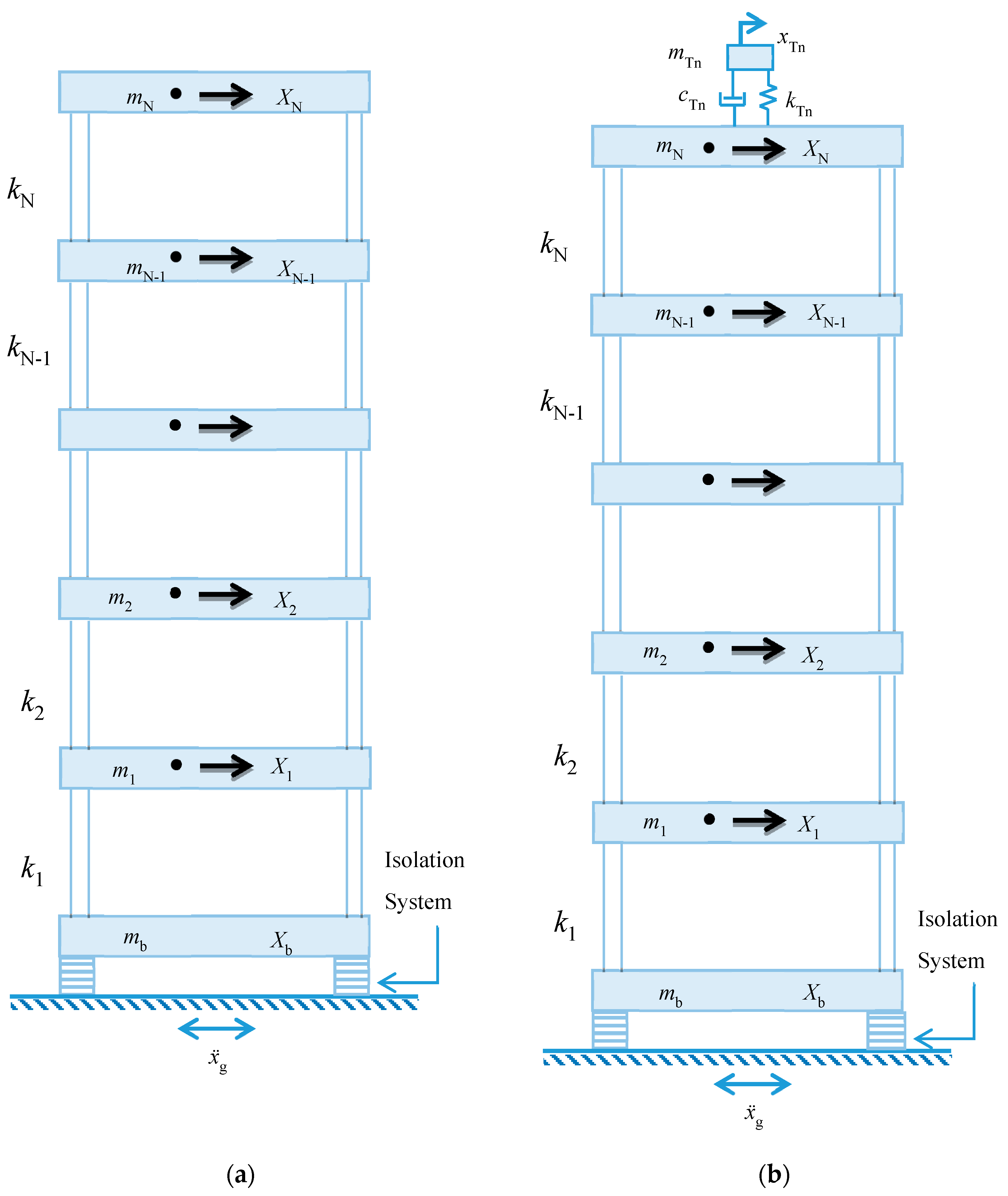
Figure 1. Schematic models of a N-story building with (a) base-isolation (BI), (b) BI + single tuned mass dampers (STMD) at top floor, (c) BI + multiple tuned mass dampers (MTMDs) at top floor, and (d) BI + distributed multiple tuned mass dampers (d-MTMDs).
Applsci 10 01230 g001aApplsci 10 01230 g001b
Figure 2. Schematic diagrams for (a) N-Z and (b) tuned mass dampers (TMD).
Applsci 10 01230 g002
Figure 3. Response spectra of the sets of DBE and MCE earthquake ground motions.
Applsci 10 01230 g003
Figure 4. Time history and Fourier Amplitude Spectra (FAS) of top floor acceleration and bearing displacement of 5 story BI and BI equipped by TMD schemes under LA04 earthquake ground motions.
Applsci 10 01230 g004
Figure 5. Reduction in average peak bearing displacement of BI and BI equipped by TMD schemes under DBE earthquake ground motions.
Applsci 10 01230 g005
Figure 6. Reduction in average of peak top floor acceleration of BI and BI equipped by TMD schemes under DBE earthquake ground motions.
Applsci 10 01230 g006
Figure 7. Cumulative probability distribution functions of maximum bearing displacement, peak top floor acceleration, and normalized shear force for 5-story building.
Applsci 10 01230 g007
Figure 8. Cumulative probability distribution functions of maximum bearing displacement, peak top floor acceleration, and normalized shear force for 10-story building.
Applsci 10 01230 g008
Figure 9. Procedure for seismic fragility analysis of base-isolated building equipped with TMD schemes.
Applsci 10 01230 g009
Figure 10. Bearing displacement simplified fragility curves for 5-story base-isolated building equipped with TMDs.
Applsci 10 01230 g010
Figure 11. Bearing displacement simplified fragility curves for 10-story base-isolated building equipped with TMDs.
Applsci 10 01230 g011
Table 1. List of the design-based earthquakes (DBE)-level earthquake ground motions used in the study and the event details.
SAC NameRecordYearEarthquake MagnitudeDistance (km)Scale FactorNumber of pointst (s)Duration (s)PGA (g)
LA01Imperial Valley19406.9102.0126740.0253.460.46
LA02Imperial Valley19406.9102.0126740.0253.460.68
LA03Imperial Valley19796.54.11.0139390.0139.380.39
LA04Imperial Valley19796.54.11.0139390.0139.380.49
LA05Imperial Valley19796.51.20.8439090.0139.080.3
LA06Imperial Valley19796.51.20.8439090.0139.080.23
LA07Landers19927.3363.240000.0279.980.42
LA08Landers19927.3363.240000.0279.980.43
LA09Landers19927.3252.1740000.0279.980.52
LA10Landers19927.3252.1740000.0279.980.36
LA11Loma Prieta19897121.7920000.0239.980.67
LA12Loma Prieta19897121.7920000.0239.980.97
LA13Northridge19946.76.71.0330000.0259.980.68
LA14Northridge19946.76.71.0330000.0259.980.66
LA15Northridge19946.77.50.7929900.00514.9450.53
LA16Northridge19946.77.50.7929900.00514.9450.58
LA17Northridge19946.76.40.9930000.0259.980.57
LA18Northridge19946.76.40.9930000.0259.980.82
LA19North Palm Springs198666.72.9730000.0259.981.02
LA20North Palm Springs198666.72.9730000.0259.980.99
Table 2. List of the maximum considered earthquakes (MCE)-level earthquake ground motions used in the study and the event details.
ZSAC NameRecordYearEarthquake MagnitudeDistance (km)Scale FactorNumber of Pointst (s)Duration (s)PGA (g)
LA21Kobe19956.93.41.1530000.0259.981.28
LA22Kobe19956.93.41.1530000.0259.980.92
LA23Loma Prieta198973.50.8225000.0124.990.42
LA24Loma Prieta198973.50.8225000.0124.990.47
LA25Northridge19946.77.51.2929900.00514.9450.87
LA26Northridge19946.77.51.2929900.00514.9450.94
LA27Northridge19946.76.41.6130000.0259.980.93
LA28Northridge19946.76.41.6130000.0259.981.33
LA29Tabas,19747.41.21.0825000.0249.980.81
LA30Tabas,19747.41.21.0825000.0249.980.99
LA31Elysian Park (simulated) 7.117.51.4330000.0129.991.3
LA32Elysian Park (simulated) 7.117.51.4330000.0129.991.19
LA33Elysian Park (simulated) 7.110.70.9730000.0129.990.78
LA34Elysian Park (simulated) 7.110.70.9730000.0129.990.68
LA35Elysian Park (simulated) 7.111.21.130000.0129.990.99
LA36Elysian Park (simulated) 7.111.21.130000.0129.991.1
LA37Palos verdes (simulated) 7.11.50.930000.0259.980.71
LA38Palos verdes (simulated) 7.11.50.930000.0259.980.78
LA39Palos verdes (simulated) 7.11.50.8830000.0259.980.5
LA40Palos verdes (simulated) 7.11.50.8830000.0259.980.63