Article

Dynamic Analysis and Security Characteristics of Carrier-Based Aircraft Arresting in Yaw Condition

1
State Key Laboratory of Mechanics and Control of Mechanical Structures, Nanjing University of Aeronautics and Astronautics, Nanjing 210016, China
2
Key Laboratory of Fundamental Science for National Defense-Advanced Design Technology of Flight Vehicle, Nanjing University of Aeronautics and Astronautics, Nanjing 210016, China
*
Authors to whom correspondence should be addressed.
Appl. Sci. 2020, 10(4), 1253; https://doi.org/10.3390/app10041253
Submission received: 22 January 2020 / Revised: 31 January 2020 / Accepted: 5 February 2020 / Published: 13 February 2020
(This article belongs to the Section Mechanical Engineering)

Abstract

:
In order to research the safety characteristics of carrier-based aircraft in yaw arrest, a complete dynamic model of the arresting system of a certain type of aircraft was developed to understand more about its dynamic properties. Based on the discrete kink-wave model, a simulation of centering arrest was conducted. The simulation results were compared with experimental data from the United States (US) military standards, demonstrating that the basic changing laws are almost the same. On the basis of centering arrest, a simulation of yaw arrest was carried out. The results show that in yaw state, the difference in the lengths of the arresting cables on either side of the hook is smaller in the early stage after the hook hangs on the rope, which leads to little influence on load fluctuation produced by the kink-wave. With the increase in arresting distance, the difference in the lengths of the arresting cables on either side becomes larger, resulting in a situation in which the cable tension on the departure side will gradually become greater than that on the opposite side. In this situation, yaw landing has a negative impact on the characteristics of arresting safety, and the excessive yaw angle causes the aircraft to rush out of the safe landing area.

1. Introduction

In order to ensure the safety and accuracy of carrier-based aircraft, the United States (US) Navy took the lead after the 1970s in using the “all-weather electronic landing aid system” to assist the pilot in landing safely [1]. At present, the very short-term motion prediction technology of the aircraft carrier has become more and more mature [2]. However, because the carrier aircraft landing process is always affected by many complex factors, such as deck motion, deck airflow field, aerodynamic performance of carrier aircraft, and so on, the carrier aircraft is still not able to be completely yaw free and hook the arresting cable in the middle [3,4].
The United States has carried out a large number of flight tests and published relevant test result curves on the topic of arresting. Most of the test reports only refer to the situation of centering arrest under the condition of no off-center or yaw. With respect to yaw arrest, only a few fitting curves of measured data have been published; however, the mechanism and theoretical analyses of yaw arrest were not disclosed.
In recent years, theoretical research of arresting devices is more comprehensive, but theoretical research and simulation analysis of arresting dynamic characteristics are not perfect. The relevant research on arresting dynamic characteristics mostly uses simplified spring linear force or the corresponding stress value curve [5,6,7] from the US military standard as input, and simplifies the arresting part (i.e., arresting rope and arresting machine) on the ship. In 1954, Thomlinson [8] established the kinematic equation between the fuselage and the arresting hook by analyzing and constructing the geometric connection relationship, and further analyzed the influence of the deck angle on the angular velocity of the rebound of the arresting hook. Lawrence [4] analyzed the main factors affecting the peak load of the arresting hook during the arresting process, including landing weight, landing speed, and initial eccentricity of landing, and based on the data statistics of the arresting system, the matching formula and curve of the arresting force were obtained. In 1959, Taylor [9] conducted a wind tunnel test with a speed reducer under the fuselage of the aircraft. Anderson et al. [10] studied the thrust reverser of a jet aircraft. In 1973, Hsin [11] analyzed the movement of the aircraft after grounding, and found that under the joint action of the arresting device and the arresting cable, the taxiing distance of the aircraft was significantly shortened and the aircraft could effectively be prevented from rushing out of the restricted area. The simulation results showed that the arresting device is expected to improve the controllability of the aircraft. In 2004, a US company published a safety report [12] in which the collision between the arresting hook and the arresting cable support was studied. Zhang et al. [13] optimized the aircraft dynamics in the arresting system and Zhang et al. [14] analyzed the result trend of eccentrically biased arresting. In the above studies, the function of the arresting system was introduced and proven to be effective in the landing process of carrier-based aircraft, but the influence of the kink-wave on the arresting force was ignored. In fact, when the carrier-based aircraft finishes landing and the arresting hook just touches the arresting cable, it is in the initial stage of engagement, and the arresting hydraulic system has not yet played a damping role. The arresting force in this stage is mainly produced by the initial tension of the arresting cable, which produces a kink-wave, which plays a major role in this early stage. When the transverse wave propagates and reflects between the engagement point of the hook cable and the deck pulley, it leads to the bending of the arresting cable, and then affects the arresting cable tension.
Generally, the experimental or theoretical research on the arresting of carrier-based aircraft is mainly focused on the process of centering arrest, and the research on the kink-wave is also mainly focused on the process of centering arrest. Few scholars have studied the dynamics of yaw arrest while considering the kink-wave in the meantime. Peng et al. [15] explored the dynamic explanations for the lateral swing motion of the hook in yaw state but did not proceed to study the influence of yaw state on the whole arresting process. For this paper, based on a discrete kink-wave model, the arresting dynamic model was established and its accuracy was verified. On this basis, the simulation calculation of the yaw arrest process was carried out, and the influence of different yaw angles on the kink-wave, arresting cable tension, arresting dynamic characteristics, and arresting safety characteristics was analyzed.

2. Arresting Dynamics Model of Carrier Aircraft

2.1. Research Object

The arresting system is shown in Figure 1. After the carrier aircraft enters the site, according to the established method, the arresting hook acts as a bridge connecting the aircraft and the road surface, transmitting the arresting force to the fuselage, thus forcing the aircraft to decelerate rapidly, generally stopping in a safe area within 3 s. Therefore, the decelerating motion characteristic of the carrier aircraft is one of the most important factors in determining the deck length design, and is also an important factor in determining the arresting safety characteristics.
The stress state of the aircraft is complex after the cable is hung with the arresting hook. In the process of arresting, the arresting hook is meshed with the braking arresting cable on the runway. The arresting cable is connected to the arresting machine on both sides of the runway through the arresting belt. The arresting cable rebounds rapidly under the tension provided by the arresting machine, so that the arresting resistance is transmitted to the aircraft. Therefore, calculating and analyzing the force provided by the arresting machine a short time after the carrier aircraft lands is very important.

2.2. Drag Force Model of Carrier Aircraft

Due to the complexity of the forces on the carrier aircraft in the process of landing and arresting, and in order to facilitate the analysis, the force on the aircraft in the process of facing the ship is simplified as follows [16]:
  • The runway is a plane, and the aircraft’s head is parallel to the runway plane;
  • In the process of arresting, the vibration after the engagement of the hook and cable is not considered, and the sum of forces in the cable (TL and TR) are shown in the exact opposite direction of aircraft movement;
  • The influence of the vertical height of the carrier aircraft on the arresting resistance is not considered.
When centering and arresting (without considering the eccentric yaw), the arresting resistance of the carrier aircraft is as shown in Figure 2.
According to Figure 2, the calculation formula of the blocking resistance is as follows:
{ F x = T L cos β + T R cos β cos β = S S 2 + D 2
where F x refers to the arresting force acting on the carrier aircraft; TL refers to the pulling force of the left arresting cable; TR refers to the pulling force of the right arresting cable; β refers to the angle between the line connecting the hook cable engagement point and the pulley, and the heading; S refers to the displacement of the carrier aircraft; and D refers to half of the distance between the two pulleys on the deck.
In the case of yaw arrest, taking the right yaw as an example, the force of yaw arrest of the carrier aircraft is as shown in Figure 3.
According to Figure 3, the calculation formula of blocking resistance is as follows:
{ F x = T L cos φ L + T R cos φ R φ L = θ L φ , φ R = θ R + φ cos θ L = S cos φ ( D + S sin φ ) 2 + ( S cos φ ) 2 cos θ R = S cos φ ( D S sin φ ) 2 + ( S cos φ ) 2
where θL is the angle between the left arresting cable and the longitudinal direction, θR is the angle between the right arresting cable and the longitudinal direction, φL is the angle between the left arresting cable and the heading, and φR is the angle between the right arresting cable and the heading.

2.3. Calculation Model of Arresting Device

To calculate the blocking resistance, it is necessary to obtain the change rule of the damping force output by the energy absorber of the blocking device, which is related to the movement displacement of the oblique flow control valve, the change rule of the sectional area of the oil groove on the valve, and the pressure in the accumulator [17]. The working principle of the energy absorber is shown in Figure 4.
The main difference between yaw arrest and centering arrest lies in the difference of impact angle between the left and right arresting cables of the arresting hook, which leads to a difference in arresting cable speed brought about by the left and right pulleys, and finally leads to a difference in piston displacement and speed on either side. For a certain arresting system, the output arresting cable tension is related to the damper stroke. When the weight of the arrested aircraft is constant, the same cable elongation corresponds to the same arresting cable tension [18].
When in centering arrest:
{ S r = S 2 + D 2 D N V r = S N S 2 + D 2 V f
When in right yaw:
{ S r L = ( D + S sin φ ) 2 + ( S cos φ ) 2     D N S r R = ( D     S sin φ ) 2 + ( S cos φ ) 2     D N V r L = V f cos φ L N V r R = V f cos φ R N
where N is the number of movable pulleys in the movable pulley block, Sr is the displacement of the piston, vr is the speed of the piston, Vf is the velocity of the aircraft, SrL is the displacement of the left piston, SrR is the displacement of the right piston, VrL is the movement speed of the left piston, and VrR is the movement speed of the right piston.

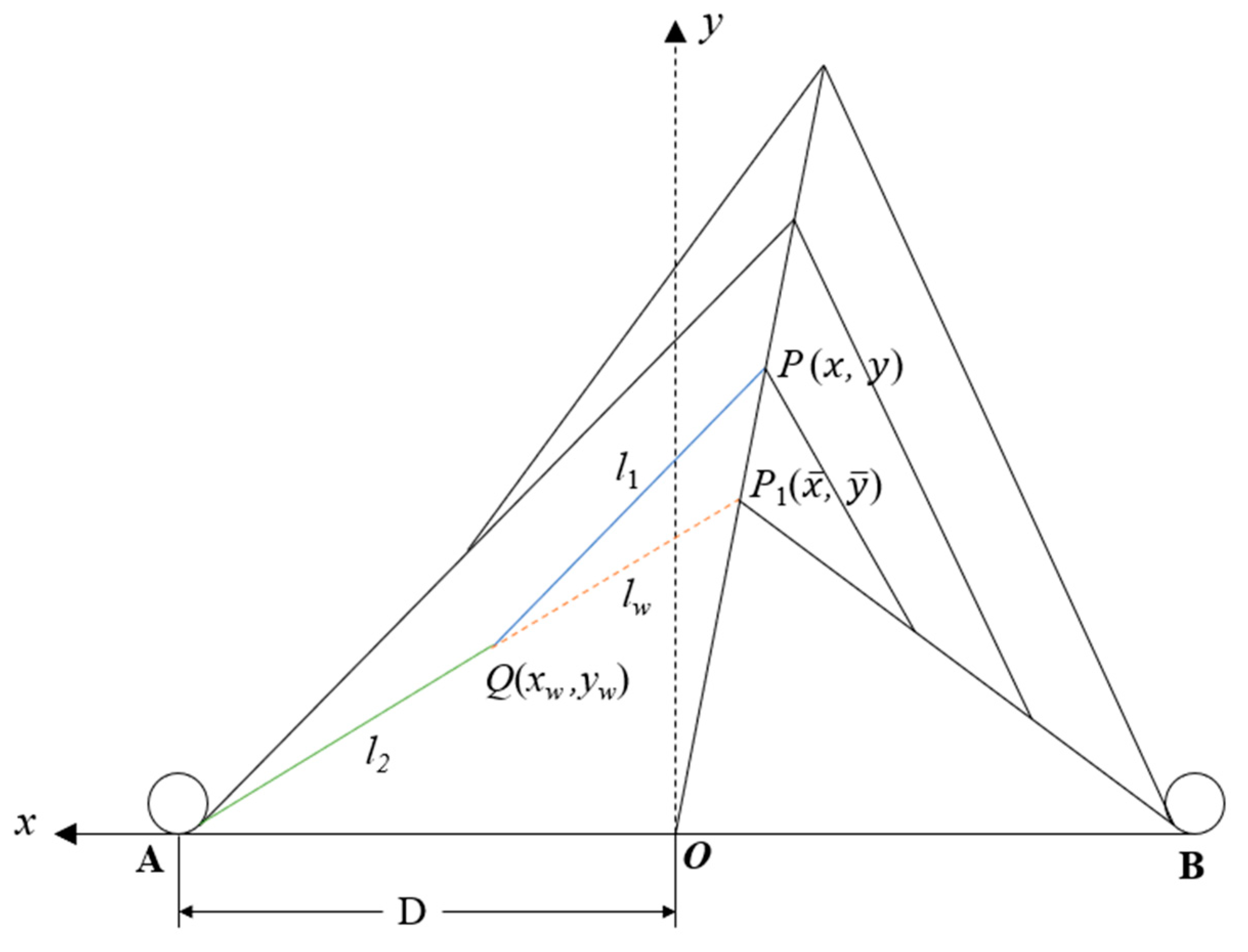
3. Calculation Model of Kink-Wave Propagation

3.1. Model Assumptions

When the arresting cable is impacted by the arresting hook, it produces a kink-wave in it. In the early stage of arresting, the kink-wave plays a major role. For this paper, a discrete kink-wave model was used. The model considers that the second kink-wave is generated at the engagement of hook and cable immediately after the first propagation of the kink-wave caused by the stress wave to the pulley, and then the third kink-wave is generated similarly. In the whole arresting process, the influence of kink-waves on the arresting load is gradually weakened. As the damping force of the arresting machine increases gradually, the influence of kink-waves is rapidly reduced. Therefore, the whole arresting system model only considers the first three kink-waves [19], and then the arresting process of the aircraft enters the stage of full hydraulic resistance force.
In the case of vertical impact, the stress on the rope can be regarded as only related to the impact velocity. In this case, the kink-wave velocity [20] is:
w = c ( 0.5 2 / 3 ( v 0 / c ) 4 / 3 0.5 2 / 3 ( v 0 / c ) 4 / 3 )
where w is the kink-wave speed, c is the longitudinal wave speed, and v0 is the contact point speed of the hook and cable.
When building the kink-wave and arresting system models, the following simplifications were adopted:
  • There is no relative sliding between the arresting hook and the arresting cable;
  • The component force of the arresting hook in the vertical direction is not considered;
  • At any time, the tension of the arresting cable on one side of the arresting hook is the same everywhere;
  • It is assumed that the arresting cable is the same cable with the same material;
  • The arresting cable is in the linear elastic range during the arresting process.

3.2. Model Comparison of Centering and Yaw Arrest

The form of the arresting cable relative to the centering arrest considering kink-wave is shown in Figure 5.
The arresting cable configuration on one side at the set time is shown in Figure 5. To establish a coordinate system, O is the origin, ( x w , y w ) are the coordinates of the bending point Q, ( x , y ) are the real-time coordinates of the aircraft, ( x ¯ , y ¯ ) are the coordinates of the aircraft at the end of the previous kink-wave, l1 and l2 are the lengths of the cable from the arresting hook to the bending point and the bending point to the pulley, and lw is the distance of the heavy kink-wave.
When yaw arrest (right yaw) takes the arresting form of the kink-wave into account, its general form is shown in Figure 6.

3.3. Calculation Method of Kink-Wave

In the calculation of the kink-wave, the trapezoid formula of the Euler method was used, and the convergence can be guaranteed when the simulation step length is small enough. Assuming that the acceleration, speed, and displacement of the aircraft at the previous time are a 0 , v 0 , and S 0 , and the acceleration, speed, and displacement of the aircraft at the current time are a 1 , v 1 , and S 1 , taking the time step as Δ t = 0.0001 s , then:
{ v 1 = v 0 + ( a 0 + a 1 ) Δ t / 2 s 1 = s 0 + ( v 0 + v 1 ) Δ t / 2
From Figure 5 above:
{ l 1 = ( x w x ) 2 + ( y y w ) 2 l 2 = ( D x w ) 2 + y w 2 x w = l w cos θ + x ¯ , y w = y ¯ l w sin θ l w = t 0 t w   d t , θ = a r c t a n ( y ¯ D + x ¯ )
where t0 and y ¯ are the starting time of the kink-wave and the displacement of the aircraft at that time, respectively, and θ is the angle between the line connecting the hook cable engagement point and the pulley, and the transverse.
According to Hooke’s law, the tension of the arresting cable can be obtained:
{ T = E q l δ δ = l 1 + l 2 D 2 N z
where E and q are the elastic modulus and cross-sectional area of the arresting cable, respectively, l is the length of the cable from the unilateral pulley to the engagement point of the hook cable, and z is the moving distance of the moving pulley block.
Then, the drag of the arresting hook acting on the aircraft can be obtained, that is, the hook load:
H T = T L cos ( arctan ( x w L x y y w L ) φ ) + T R cos ( arctan ( x x w R y y w R ) + φ )
where ( x w L , y w L ) and ( x w R , y w R ) are the coordinates of the left and right bending points at the starting time of the kink-wave, respectively, and HT is the hook load.
In different periods of kink-waves, the initial moment and initial bending angle on either side are different, which makes the calculation formula of some lengths different. Therefore, it is very difficult to establish a continuous model of kink-waves to describe the whole arresting process [19]. In this paper, the discrete method was used to build the model, and the accumulation sum was used to replace the integral, so that the initial state is known and the whole solution model is determined.

4. Model Checking

4.1. Model Solving Process

After the calculation of the first three kink-waves, the arrest entered the period of full hydraulic damping. During this period, Simulink was used to build the calculation model of the arresting force, and ode113 solver was used for the model. This solver is a variable step size solver with high accuracy when the error tolerance is strict. The relative error tolerance was set to 1 × 10⁻⁴ and the maximum step size to 0.001 s. The state variables at this period were used as outputs (the displacement and speed of the aircraft, the angle between the left and right side of the arresting cable and the initial position, the displacement and speed of the two sides of the piston, etc.), then the dynamic calculation of the arresting process continued until the aircraft stopped and the simulation ended. The specific flow of the model solution is shown in Figure 7.

4.2. Model Validation

For comparison and verification, taking the MK7-3 arresting device as an example for calculation, the model calculation parameters [21] are shown in Table 1.
When in centering arrest, the curve of the arresting resistance with the travel is shown in Figure 8. It can be seen from Figure 8 that when considering the kink-wave, the arresting resistance has obvious fluctuation in the initial stage, which shows that the effect of the kink-wave in the arresting cable cannot be ignored.
As shown in Figure 9, and from the comparison results of the two groups of data, it can be seen that in the initial stage, the arresting force fluctuates under the influence of the kink-wave, and both simulation and test data [6] show the feature of kink-waves. The load fluctuation is the result of repeated propagation of stress waves between the deck pulley and hook cable engagement point. There are some differences between the simulation results and the test data in the middle stage, but the form of the change of the arresting force is consistent in the process of arresting, so the simulation results have good consistency and credibility in general.

5. Calculation and Analysis

The yaw angle was set in the model to simulate the yaw arrest dynamics. The yaw of all calculation examples is right deviation, and other parameters are consistent with the simulation of centering arrest.

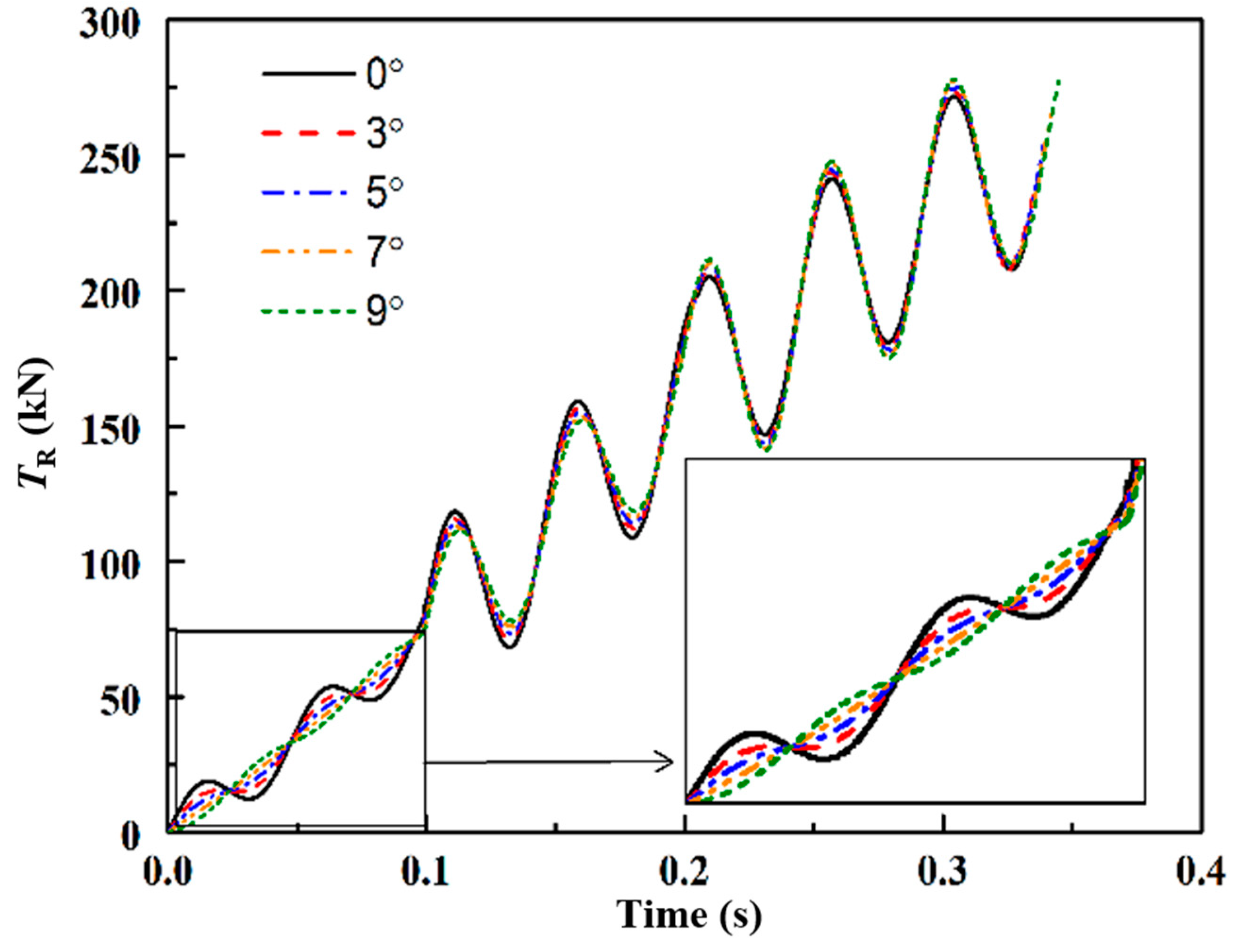
5.1. The Influence of Yaw Angle on Kink-Wave

In the case of right yaw arrest, the triple kink-wave on the right side ends first, and then the third kink-wave on the left side ends. The influence of yaw angle on the resistance of both sides during the first triple kink-wave was analyzed, and the results are shown in Figure 10 and Figure 11.
The results of the time length of the triple kink-wave on both sides at different yaw angles are listed in Table 2 for comparative analysis.
It can be seen from the results that there is no difference in the time length of the first kink-wave between the left and right sides, both of which are about 0.0993 s. After the propagation of the first kink-wave, the time length of the left kink-wave increases slightly with the increase of eccentricity, and the time length of the right kink-wave decreases slightly with the increase of yaw angle.
The main reason is that when the first kink-wave propagates, the initial length of the arresting cables on either side is the same, and the kink-wave velocity is slightly different, so the time of the first kink-wave propagation is basically the same. After the end of the first kink-wave, the length of the arresting cables on either side is different. When the right yaw arrests, the right arresting cable is shorter than the left, the kink-wave propagation time is shorter, and the time difference of the same kink-wave on either side is obvious.
When the yaw angle is larger, the fluctuation of the first kink-wave on the right side is obviously weakened. When the yaw angle reaches 7°, the fluctuation is smaller. When the yaw angle reaches 9°, the fluctuation of the basic first kink-wave is not obvious.

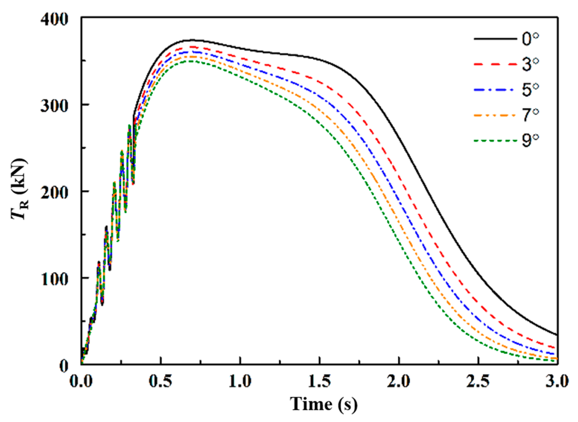
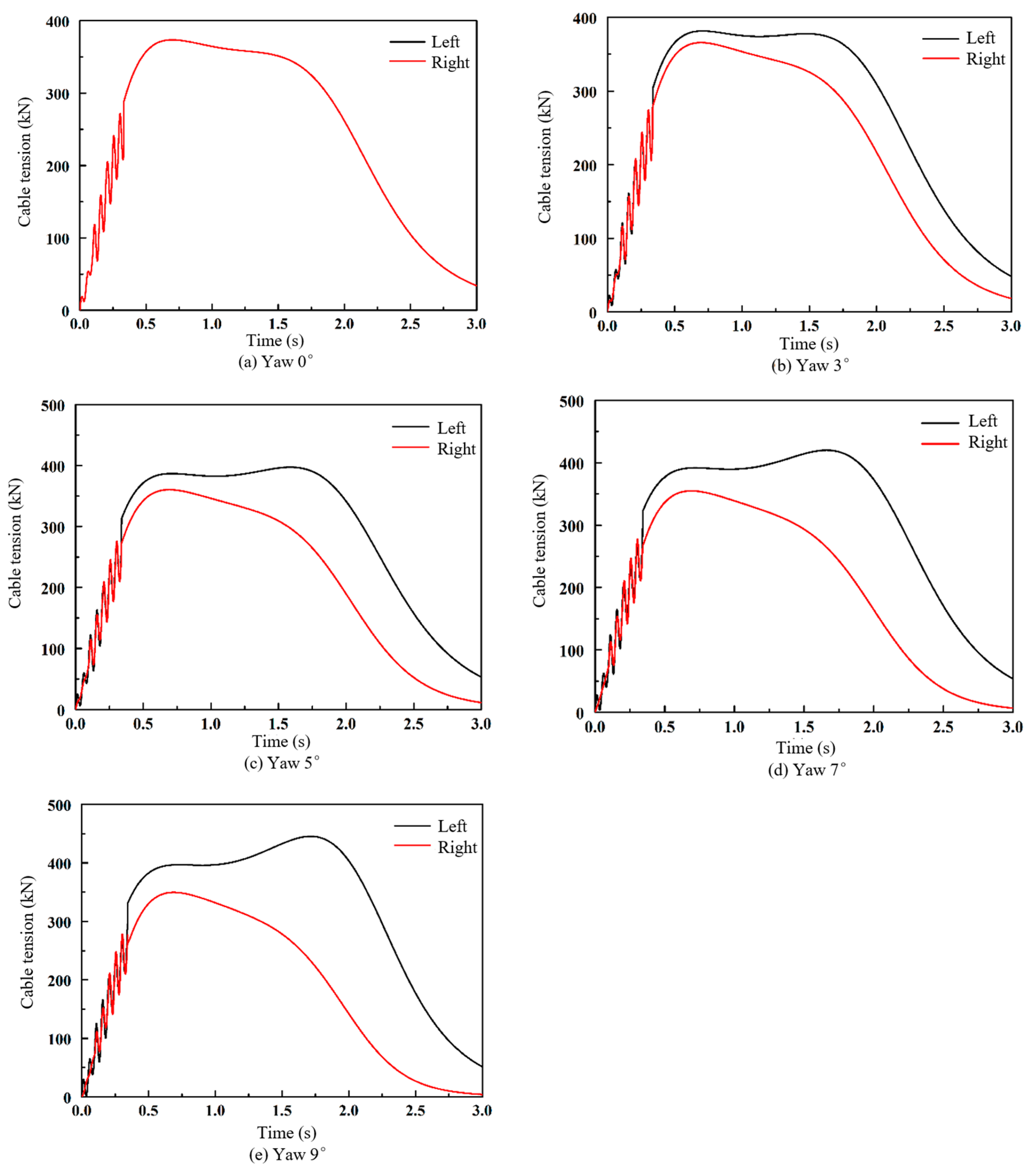
5.2. The Influence of Yaw Angle on the Tension of Arresting Cable

The maximum yaw angle was taken as 9 degrees, and the variation trend of the tension of the unilateral arresting cable when the yaw angle was 0, 3, 5, 7, and 9 degrees was analyzed. The results are shown in Figure 12 and Figure 13.
The results of the maximum belt tension on the left side and the maximum belt tension on the right side under different yaw angles are listed in Table 3 for comparative analysis.
It can be seen from the results that with the increase of the yaw angle, the cable tension of the left-side arresting system increases gradually compared with that of the centering arresting system, and the maximum belt tension of the left side with the yaw angle of 9 degrees is 445.31 kN. The belt tension of the right-side arresting system decreases gradually compared with that of the centering arresting system, and the maximum belt tension of the right side with the yaw angle of 9 degrees is 349.50 kN.
The change trend of the tension of the two sides of the arresting belt was then analyzed, when the yaw angle was 0, 3, 5, 7, and 9 degrees. The results are shown in Figure 14.
It can be seen from Figure 14 that with the increase of yaw angle, the tension difference between the two side belts is larger, and the tension of the left-side belt is larger than that of the right-side belt. Compared with the centering arresting, due to the different elongation of the arresting cables on the left and right sides, the speed of the pistons on either side is different, and the tension of the arresting belts on either side is different. The upper limit of cable tension is 784 kN, and yaw arrest does not cause drag to exceed this limit.

5.3. The Influence of Yaw Angle on the Performance of the Arresting System

The response of aircraft speed, displacement, acceleration, and arresting force when the yaw angle changes was then analyzed, as shown in Figure 15, Figure 16, Figure 17 and Figure 18.
The calculation results of the arresting system and aircraft response under different yaw angles are listed in Table 4 for comparative analysis.
It can be seen from the comparison results that the peak value of the arresting force increases slightly with the increase of the yaw angle, and has little influence on the arresting distance and the peak value of the aircraft acceleration.

5.4. The Influence of Yaw Angle on Arresting Safety

The landing area of the flight deck as shown in Figure 19 is actually the area surrounded by safety warning lines on both sides of the inclined deck, which is often referred to as the inclined landing runway. The landing runway should not only meet the safe landing requirements of the carrier aircraft, but also ensure that there is enough distance to complete the missed approach after confirming the failure of the hooking rope [22]. In addition, there should be a long enough turning area to meet the turning operation of the carrier aircraft.
In the picture:
{ B a = B T + 2 B S S a = d + Δ x 1 + Δ x 2 + Δ x 3 + S s + S t + S S
where Ba is the width of the landing runway of the aircraft deck, BT is the total width of the aircraft with the largest wing span, BS is the width of the safety margin between the safety warning sign and the aircraft’s wing tip, Sa is the total length of the landing area, d is the length of the landing area, Δ x 1   +   Δ x 2   +   Δ x 3 is the length of the blocking area, Sd is the length of the deceleration braking area, St is the length of the turning area, and SS is the length of the safety reserve area.
It is assumed that the deck landing runway width of an aircraft carrier is 40 m and the wingspan of an aircraft carrier is 24.56 m; then, BS is 7.72 m.
Under different yaw conditions, the deviation of carrier aircraft stopping is shown in Table 5.
According to the analysis of arresting offset, when the yaw angle is 5 degrees, the carrier aircraft stops just at the edge of the safe landing area. If the yaw angle is bigger than 5 degrees, the aircraft will rush out of the safe landing area, which may lead to safety accidents. Therefore, the yaw angle should be reduced as much as possible to reduce the lateral offset of the carrier aircraft, so as to prevent the aircraft from colliding with the aircraft or the ship island building outside the safe landing area in the process of arresting and improve the arresting safety.

6. Conclusions

In order to solve the problem of asymmetric arresting, a complete dynamic model of an arresting system was established. The accuracy of the model was verified by the experimental results of the US military. The dynamic simulation of yaw arrest under different conditions was carried out. The comprehensive analysis of the simulation results showed the following:
(1) In the case of yaw arrest, there is almost no difference in the length of the first kink-wave on either side. After the propagation of the first kink-wave, the time length of the kink-wave of the departure side increases slightly with the increase of the yaw angle, and the time length of the kink-wave of the deflection side decreases slightly. The influence of the yaw on the time length of the kink-wave is small.
(2) For yaw arrest, the tension of the deflection-side arresting belt is smaller than that of the middle, and the tension of the departure-side arresting belt is larger than that of the middle. With the increase of yaw angle, the difference between the peak values of the tension of the arresting belt on either side becomes increasingly larger. When the yaw angle is too large, the peak value of the tension of the departure-side arresting belt may exceed the allowable pulling force of the arresting cable, resulting in arresting failure.
(3) Yaw arrest has little influence on arresting distance, aircraft deceleration process, peak value of arresting resistance, and peak value of acceleration. With the increase of yaw angle, the arresting distance slightly decreases, and the peak values of the acceleration and arresting force also decrease slightly.
(4) For yaw arrest, when the yaw angle is less than 5 degrees, the carrier aircraft is stopped within the safe range of the landing area, and the excessive yaw angle has an adverse effect on the arresting safety characteristics.

Author Contributions

Conceptualization, X.W. and H.N.; Data curation, Y.P.; Formal analysis, Y.P.; Investigation, Y.P. and P.X.; Methodology, Y.P.; Project administration, X.W. and H.N.; Resources, X.W. and H.N.; Software, P.X.; Supervision, X.W. and H.N.; Validation, Y.P.; Visualization, P.X.; Writing—original draft, Y.P.; Writing—review and editing, Y.P. All authors have read and agreed to the published version of the manuscript.

Funding

This work was financially supported by the China Postdoctoral Science Foundation (2019M651827), Jiangsu Planned Projects for Postdoctoral Research Funds (2018K042B), the National Defense Excellence Youth Science Fun of China (2018-JCJQ-ZQ-053), the Fundamental Research Funds for the Central Universities of China (NP2017401), and the Research Fund of State Key Laboratory of Mechanics and Control of Mechanical Structures (Nanjing University of Aeronautics and Astronautics) (MCMS-0217G01). A Project Funded by the Priority Academic Program Development of Jiangsu Higher Education Institutions.

Conflicts of Interest

The authors declare no conflict of interest.

References

  1. Yang, Y.D. Review of the Carrier Approach Criteria; National Defense Industry Press: Beijing, China, 2006. [Google Scholar]
  2. Neves, M.A.S.; Rodríguez, C.A. On un-stable ship motions resulting from strong non-linear coupling. Ocean Eng. 2006, 33, 1853–1883. [Google Scholar] [CrossRef]
  3. Thomas, R.; Stephen, C.; Marshell, H. Review of the Carrier Approach Criteria for Carrier-Based Aircraft Phase I; Naval Air Warfare Center Aircraft Division Patuxent River: Saint Mary’s County, MD, USA, 2002. [Google Scholar]
  4. Lawrence, J.T. Milestones and developments in US naval carrier aviation-part II: AIAA-2005-6120. In Reston: AIAA. In Proceedings of the AIAA Atmospheric Flight Mechanics Conference and Exhibit, San Francisco, CA, USA, 15–18 August 2005. [Google Scholar]
  5. Jones, L.W. Development of Curves for Estimating Aircraft Arresting Hook Loads: ADA119551; Air Force Flight Test Center, Edwards Air Force Base: Edwards AFB, CA, USA, 1982; pp. 15–42. [Google Scholar]
  6. Naval Air Engineering Center. MIL-STD-2066(AS) Military Standard: Catapulting and Arresting Gear Forcing Functions for Aircraft Structural Design; Naval Air Systems Command, Department of the Navy: Manchester Township, NJ, USA, 1981. [Google Scholar]
  7. Department of the Air Force. Guide to Mobile Aircraft Arresting System Installation: Air Force Handbook 10–222; Secretary of the Air Force Washington: Washington, DC, USA, 2000; Volume 8, pp. 19–174. [Google Scholar]
  8. Thomlinson, J. A Study of the Aircraft Arresting Hook Bounce Problem. The Principal Director of Scientific Research (Air); Her majesty’s Stationery Office: London, UK, 1954. [Google Scholar]
  9. Taylor, R.T. An Experimental Investigation to Determine the Effect of Speed-Brake Position on the Longitudinal Stability and Trim of a Swept-Wing Fighter Airplane, 19980235623; Langley Re-search Center: Hampton, VA, USA, 1959. [Google Scholar]
  10. Anderson, S.B.; Cooper, G.E.; Faye, A.E., Jr. Flight Measurements of the Effect of a Controllable Thrust Reverser on the Flight Characteristics of a Single-Engine Jet Airplane, 19980228232; Ames Research Center: Mountain View, CA, USA, 1959. [Google Scholar]
  11. Hsin, C. Arrested Landing Studies for STOL aircraft, A73-17627 (AH); American Institute of Aeronautics and Astronautics, Annual Meeting and Technical Display: Washington, DC, USA, 1973. [Google Scholar]
  12. Engineered Arresting Systems Corporation. Safety Bulletin; Engineering Arresting System Corporation: Plasisir Credex, France, 2004. [Google Scholar]
  13. Zhang, S.S.; Jin, D.P. Nonlinear optimal control of aircraft arresting process. Acta Aeronaut. Astronaut. Sinica 2009, 30, 849–854. [Google Scholar]
  14. Zhang, Z.K.; Nie, H.; Yu, H. Dynamics Analysis for Aircraft Arresting with Yawing and Off-center. Adv. Aeronaut. Sci. Eng. 2010, 1, 327–332. [Google Scholar]
  15. Peng, Y.M.; Nie, H.; Zhang, M.; Wei, X.H. Dynamics analysis of arresting hook following engagement of an arresting cable in yaw condition. Acta Aeronaut. Astronaut. Sinica 2015, 36, 1876–1884. [Google Scholar]
  16. Zhang, X.X.; Zhang, Y.X.; Liu, Y. Method of Arresting Cable Tension Control. J. Natl. Univ. Def. Technol. 2016. [Google Scholar] [CrossRef]
  17. Zhu, Q.D.; Wen, Z.X.; Zhang, Z. Kinetic Modeling and Simulation of Shipboard Arresting System. Acta Aero-Naut. Astronaut. Sinica 2012, 33, 520–529. [Google Scholar]
  18. Liu, G.; Nie, H. Dynamics analysis for aircraft ar-resting based on absorbing aircraft kinetic energy. China Mech. Eng. 2009, 20, 450–454. [Google Scholar]
  19. George, M.L. Development of Mathematical Performance Prediction Model for Rotary–Hydraulic-Type Arresting Gears. AD893157; Navy Air Test Facility, Naval Air Station Lakehurst: Manchester Township, NJ, USA, 1972; pp. 5–27. [Google Scholar]
  20. Zhang, P.; Jin, D.P. Control of Arresting Process for Carrier Aircraft Considering Kink-wave. Acta Aero-Naut. Astronaut. Sinica 2011, 32, 2008–2015. [Google Scholar]
  21. Theriault, L.M.; Swienciski, H.J. Aircraft Compatibility and Evaluation of the Mark 7 Mod 3 Arresting Gear; Navil Air Test Facility Lakehursut N J: Saint Mary’s County, MD, USA, 1968; pp. 23–65. [Google Scholar]
  22. Naval Air Systems Command. NAVAIR 00-80T-105CV NATOPS Manual; Naval Air System Command: Patuxent River, MD, USA, 2009. [Google Scholar]
Figure 1. Schematic diagram of carrier aircraft landing and hanging cable.
Applsci 10 01253 g001
Figure 2. Schematic diagram of arresting force.
Applsci 10 01253 g002
Figure 3. Schematic diagram of yaw arrest.
Applsci 10 01253 g003
Figure 4. Principle diagram of the arresting gear energy absorber.
Applsci 10 01253 g004
Figure 5. Form of cable in centering arrest.
Applsci 10 01253 g005
Figure 6. Form of cable in yaw arrest.
Applsci 10 01253 g006
Figure 7. Diagram of calculation chart.
Applsci 10 01253 g007
Figure 8. Curve of arresting force–displacement in centering arrest.
Applsci 10 01253 g008
Figure 9. Curves comparison of arresting force–displacement in simulation and test.
Applsci 10 01253 g009
Figure 10. Port tension during kink-wave period.
Applsci 10 01253 g010
Figure 11. Starboard tension during kink-wave period.
Applsci 10 01253 g011
Figure 12. The port tape tension.
Applsci 10 01253 g012
Figure 13. The starboard tape tension.
Applsci 10 01253 g013
Figure 14. The comparison of port and starboard tape tensions: (a) when yaw angle is 0°; (b) when yaw angle is 3°; (c) when yaw angle is 5°; (d) when yaw angle is 7°; (e) when yaw angle is 9°.
Applsci 10 01253 g014
Figure 15. Displacement–time in simulation.
Applsci 10 01253 g015
Figure 16. Velocity–time.
Applsci 10 01253 g016
Figure 17. Longitudinal acceleration–time.
Applsci 10 01253 g017
Figure 18. Arresting force–displacement.
Applsci 10 01253 g018
Figure 19. The compositions of angled deck.
Applsci 10 01253 g019
Table 1. Parameters of the carrier aircraft and landing gear.
ParameterValueParameterValue
Mass of aircraft (kg)22,680Accumulator air bag volume (m3)2
Landing speed (m·s−1)63Initial pressure of accumulator (MPa)3
Maximum stopping distance (m)104Accumulator piston mass (kg)10
Piston area of energy absorber (m2)0.28Accumulator piston area (m2)1
Piston stroke of energy absorber (m)5Distance between pulleys on deck (m)34
Table 2. Time length comparison of kink-wave in yaw arrest.
Yaw AngleFirst Kink-Wave (s)Second Kink-Wave (s)Third Kink-Wave (s)
Port0.09940.20550.3320
Starboard0.09940.20550.3320
Port0.09930.20710.3360
Starboard0.09920.20350.3264
Port0.09930.20830.3390
Starboard0.09920.20230.3227
Port0.09930.20940.3419
Starboard0.09920.20100.3189
Port0.09930.21060.3450
Starboard0.09920.19980.3152
Table 3. Comparison of the port and starboard maximum belt tensions of different eccentricity.
ParametersCenteringYaw 3°Yaw 5°Yaw 7°Yaw 9°
Port maximum belt tension (kN)373.76381.63397.25420.06445.31
Starboard maximum belt tension (kN)373.76365.74360.35354.93349.50
Table 4. Comparison of performance of the arresting system of different eccentricity.
ParametersCenteringYaw 3°Yaw 5°Yaw 7°Yaw 9°
Maximum arresting force (kN)698.78698.76698.72698.68698.61
Maximum acceleration (m·s−2)30.8130.8130.8130.8030.80
Arresting distance (m)86.7686.6286.3986.0685.38
Table 5. Comparison of offsets.
ParametersCenteringYaw 3°Yaw 5°Yaw 7°Yaw 9°
Arresting offset distance (m)04.537.5310.4913.36

