Intelligent Control of the Microclimate of an Agricultural Greenhouse Powered by a Supporting PV System


Abstract
:1. Introduction
2. Dynamic Greenhouse Model
2.1. Greenhouse Model
- The main function of the cover is heat retention; usually, the cover is made of polyethylene film or glass;
- The interior air represents an internal climate that is mainly governed by temperature and humidity;
- The plants play a strategic role in water and heat balance, thanks to the evapotranspiration process [10];
- The soil influences the absorbance and diffusivity of the thermal radiation [11].
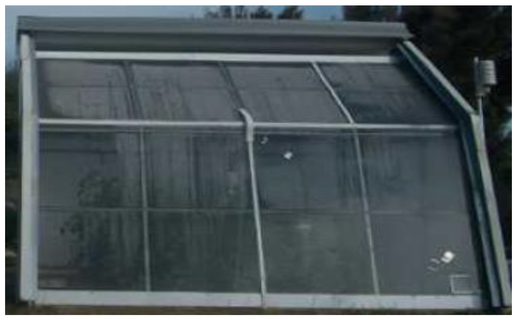
2.2. Test Lab Greenhouse under Study
2.3. Heat Balance
2.4. Water Balance
2.5. Validation of the Proposed Dynamic Model
3. Fuzzy Logic Controller for the Greenhouse
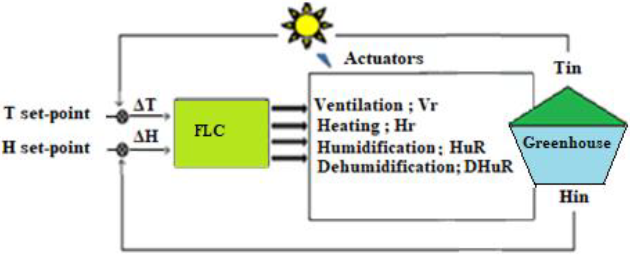
3.1. Architecture of the Fuzzy Control Unit
- A fuzzification interface that converts linguistics input variables into numerical values;
- A database unit that includes membership functions that need an “interface engine” in the fuzzy rules; and
- A defuzzification processor that generates crisp control output for specific actuators.
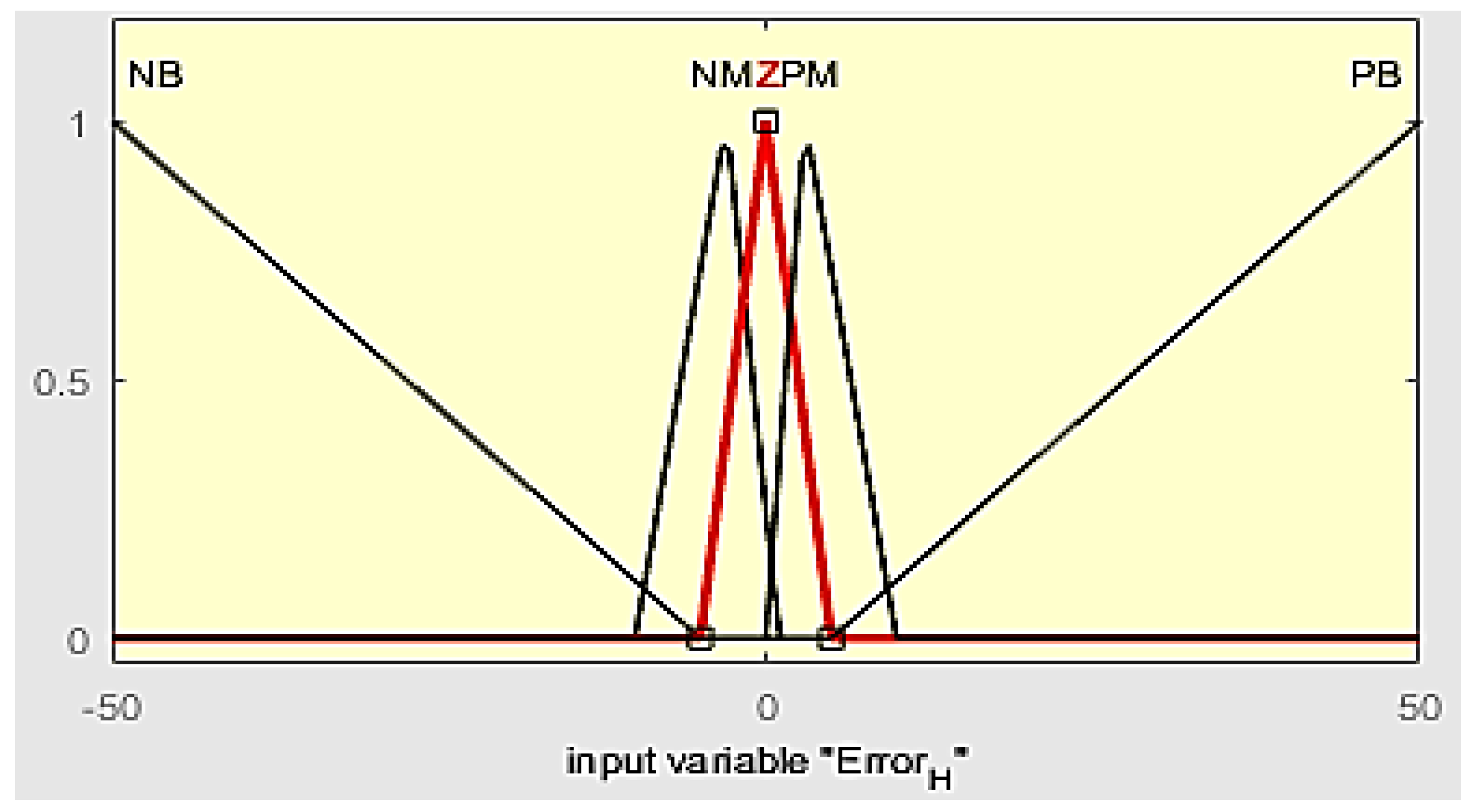
3.2. Temperature Control
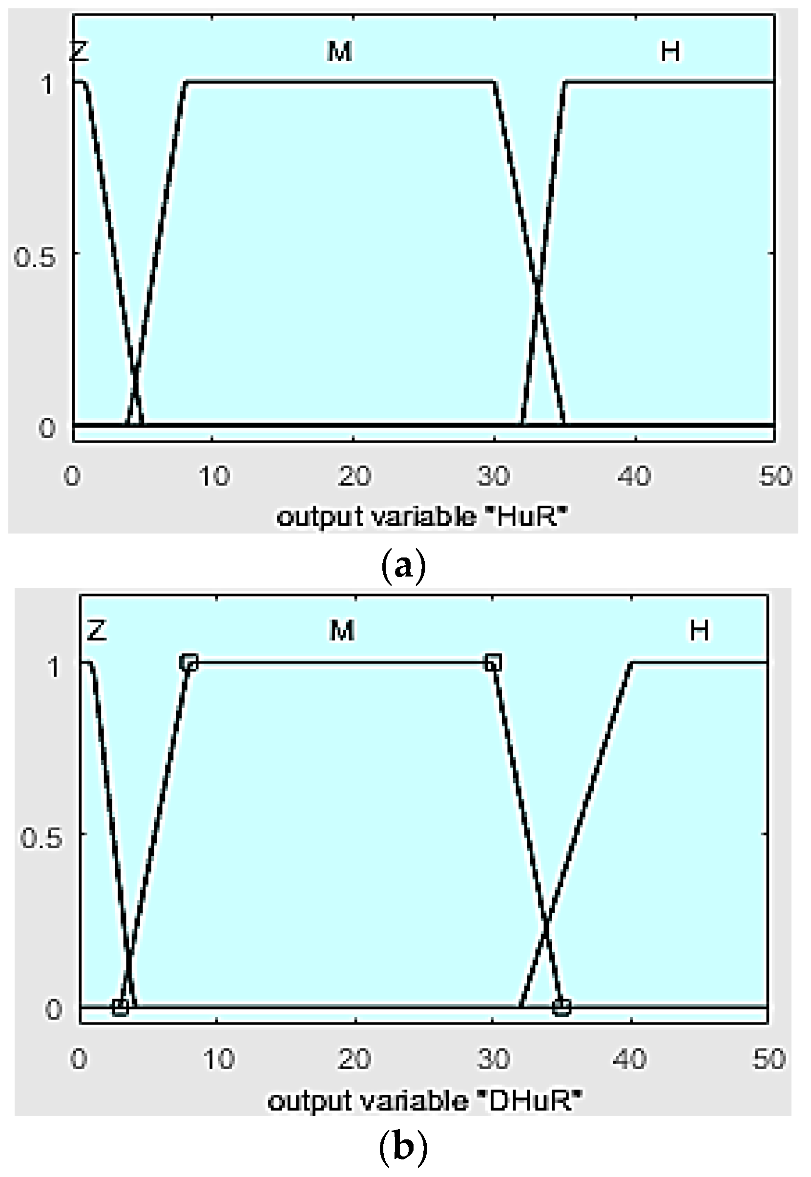
3.3. Relative Humidity Control
- If (ΔT is negative big) then (ventilation is high) and (heating is zero); and
- If (ΔH is zero) then (humidification is zero) and (dehumidification is zero).
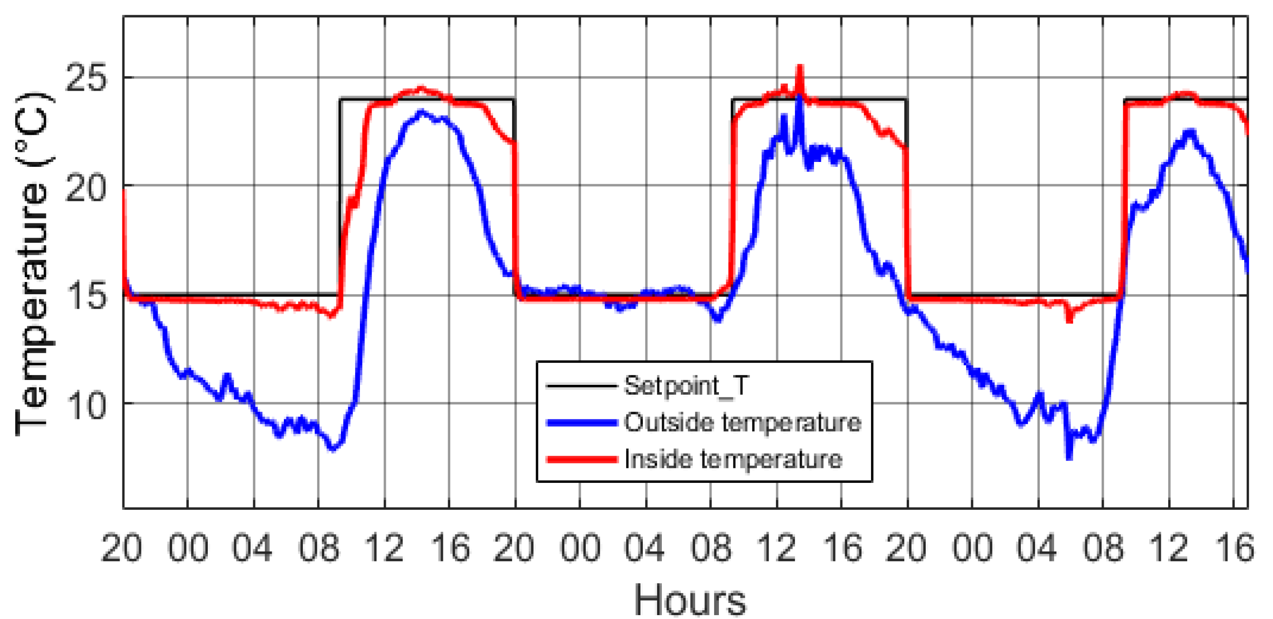
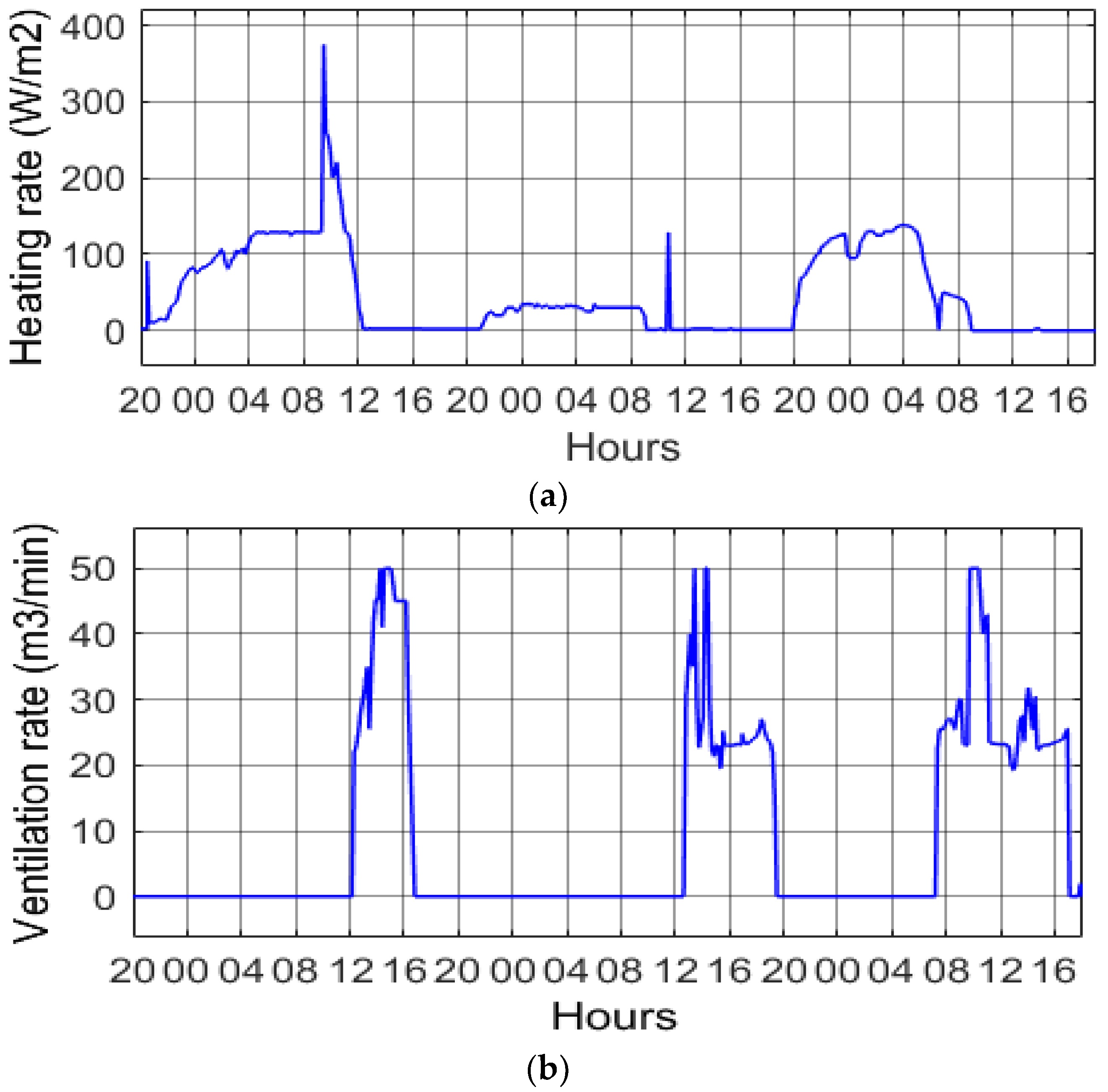
4. Simulations and Results
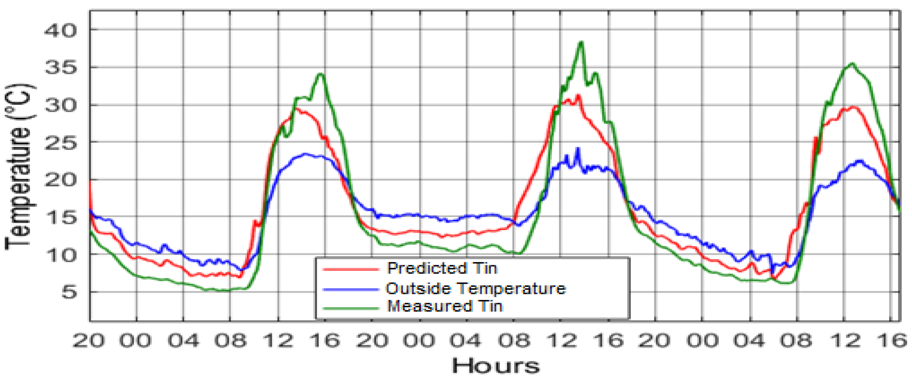
4.1. Temperature
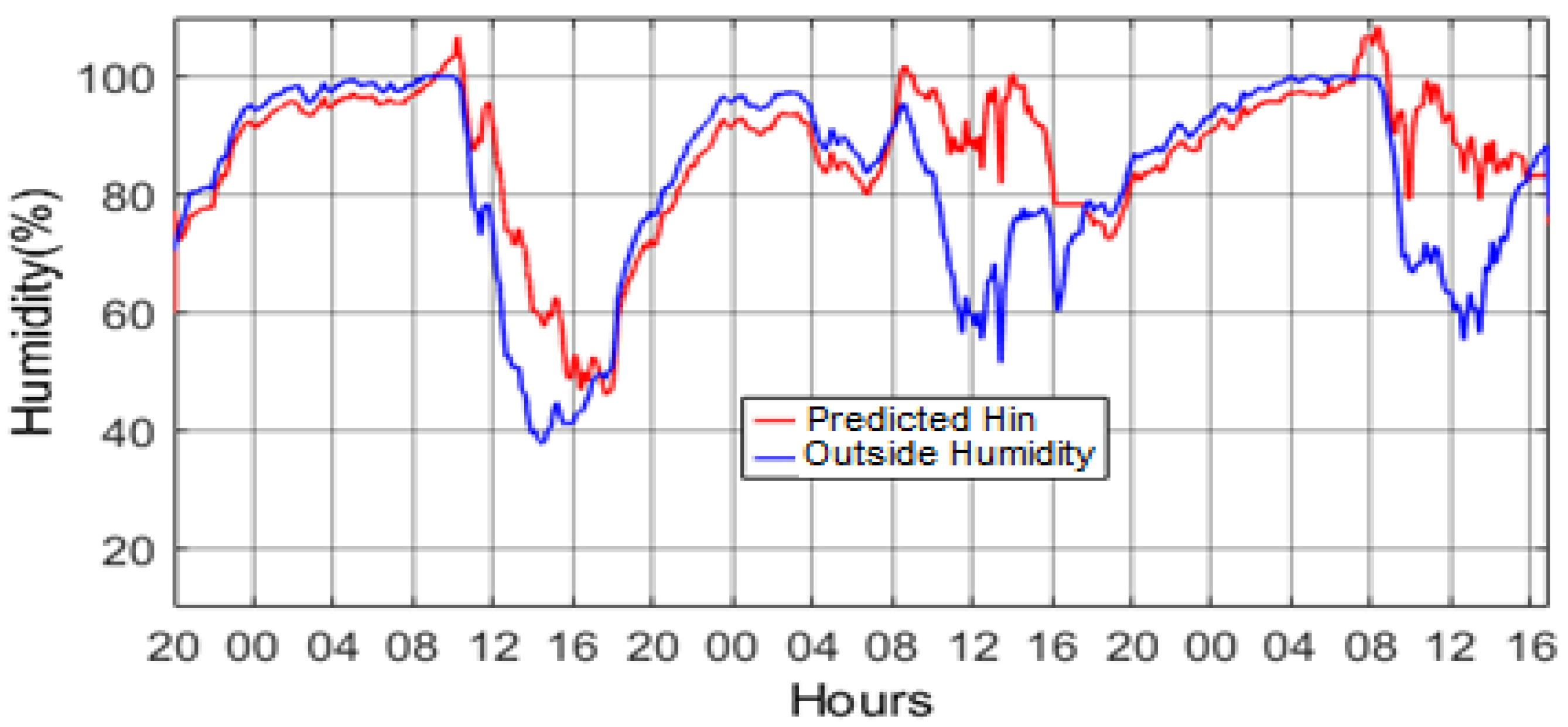
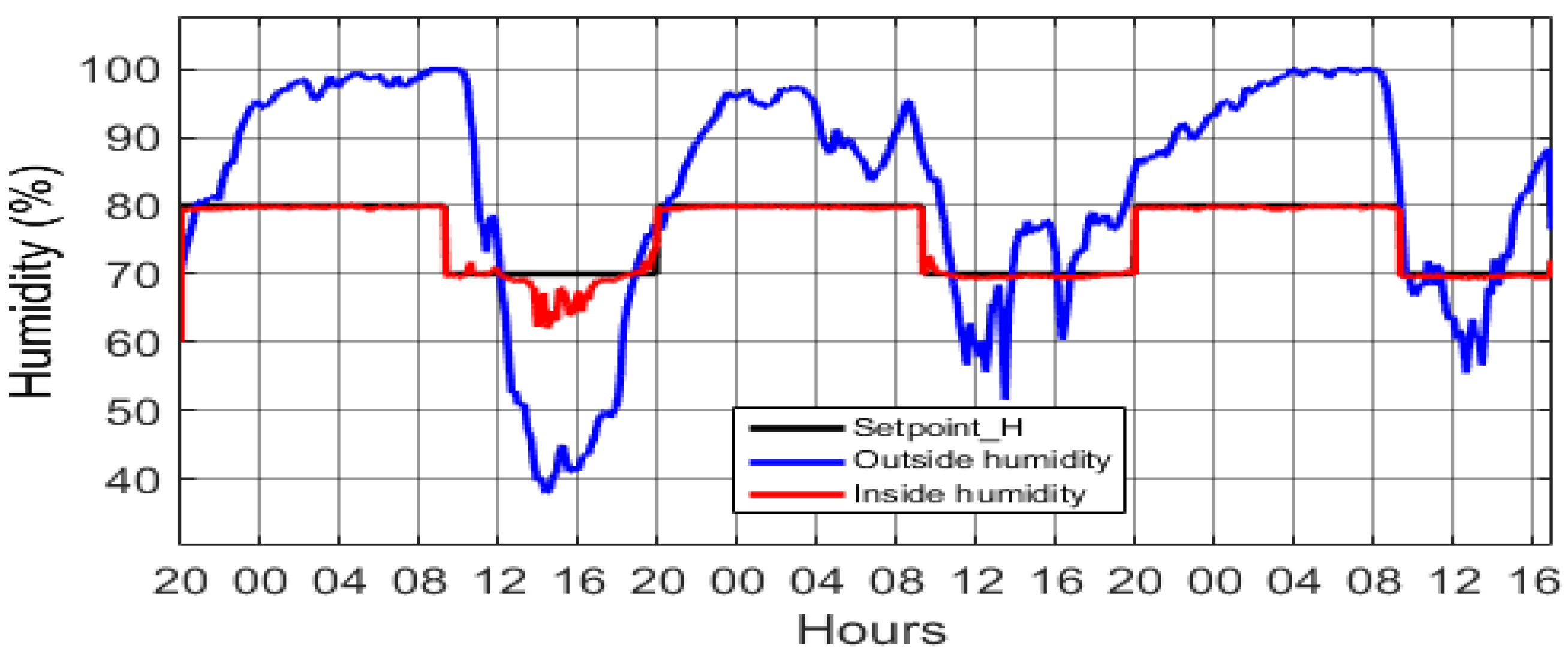
4.2. Humidity
5. Photovoltaic System
5.1. Energy Management Approach
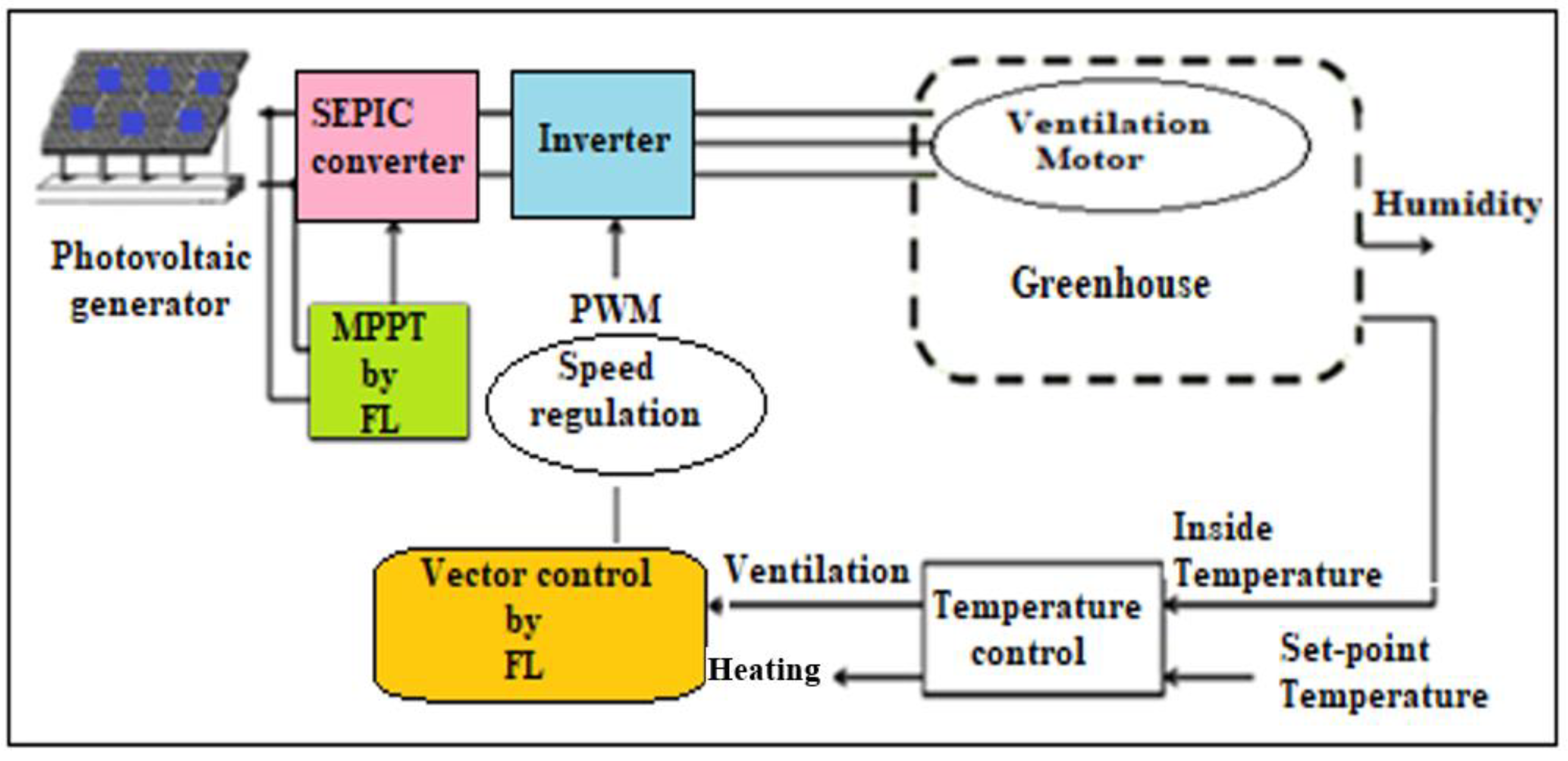
5.2. System Description
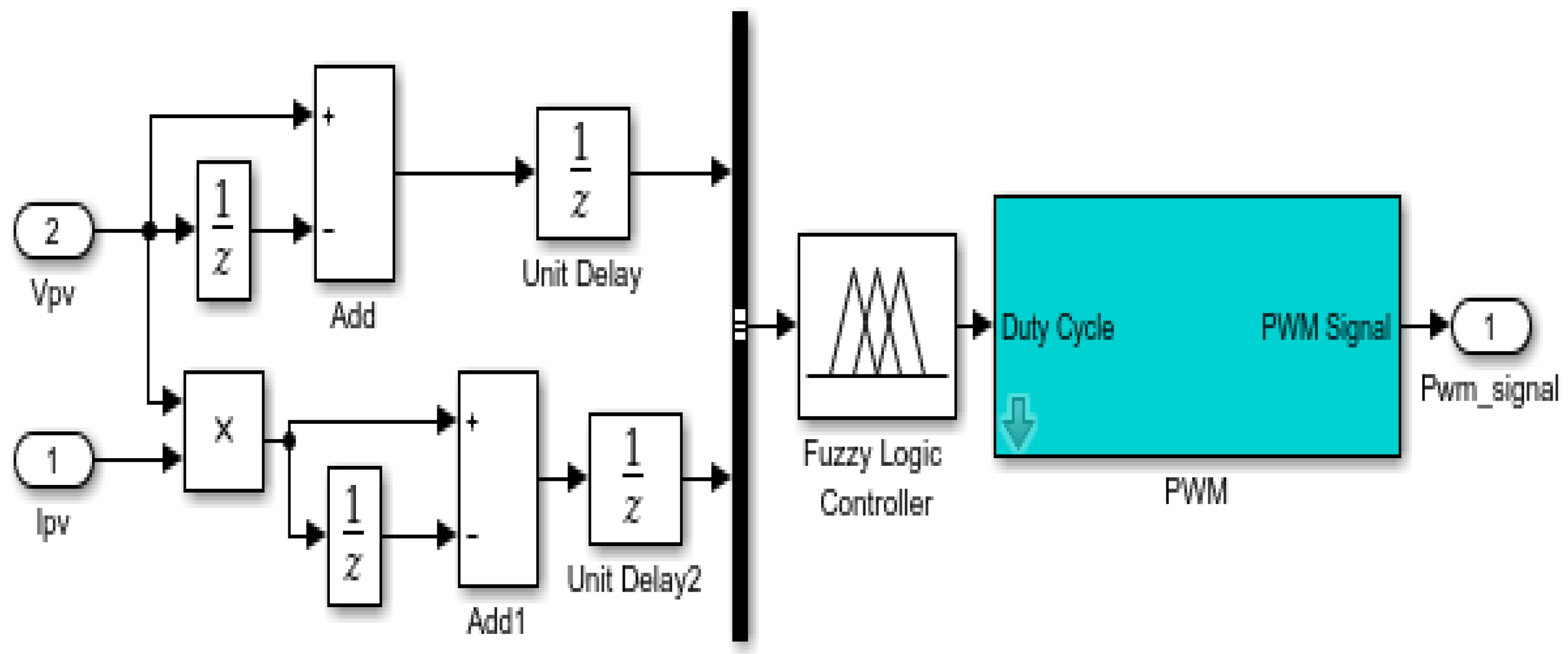
- A PV generator, whose maximum power is assured by the maximum power point tracking MPPT command based on the perturb and observe (P&O) method;
- A power stage consisting of a continuous-to-continuous converter, called single ended primary inductor converter “SEPIC”, and an inverter (red block);
- An asynchronous motor that drives the fan; and
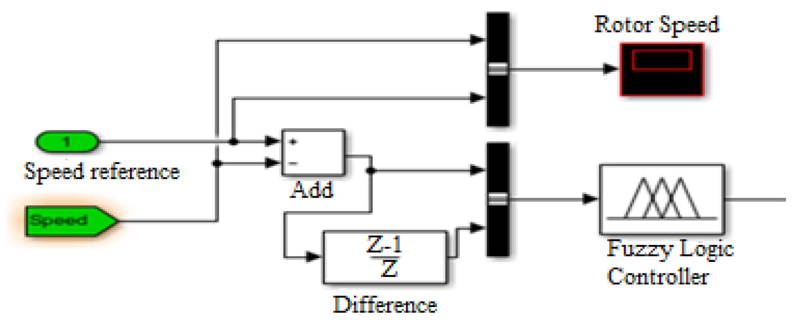
- A vector control optimized by fuzzy logic for asynchronous motor speed control (yellow block).
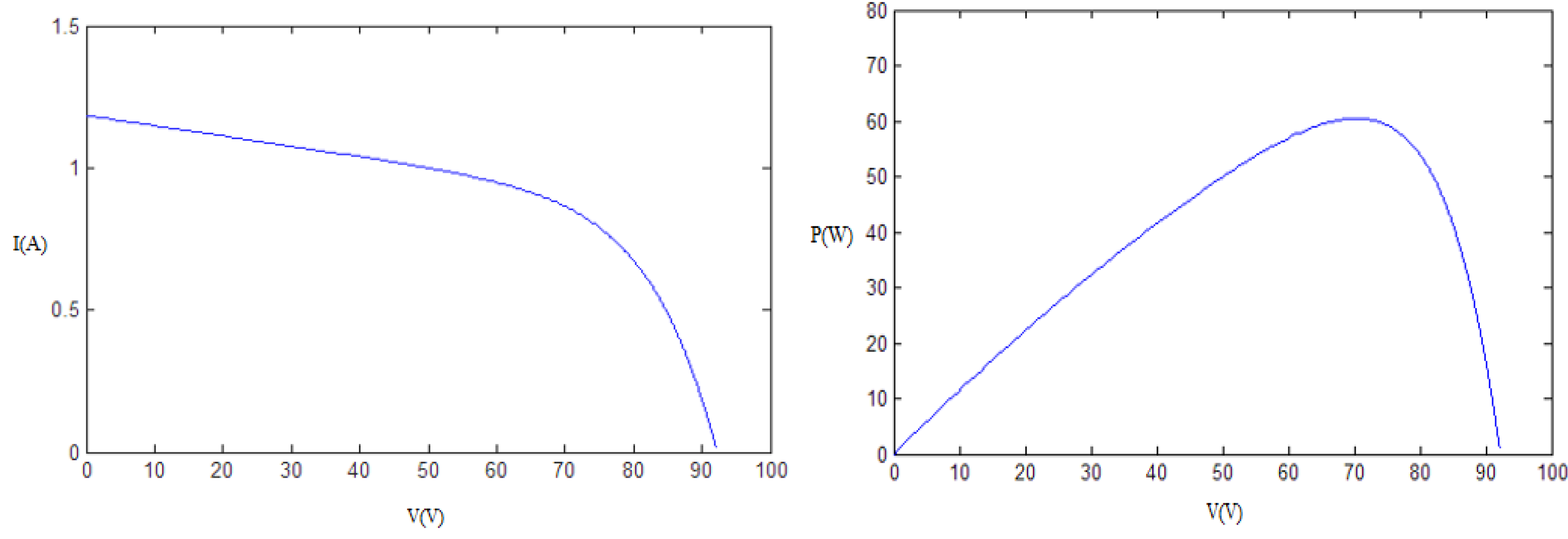
5.2.1. Parameters of the PV Modules
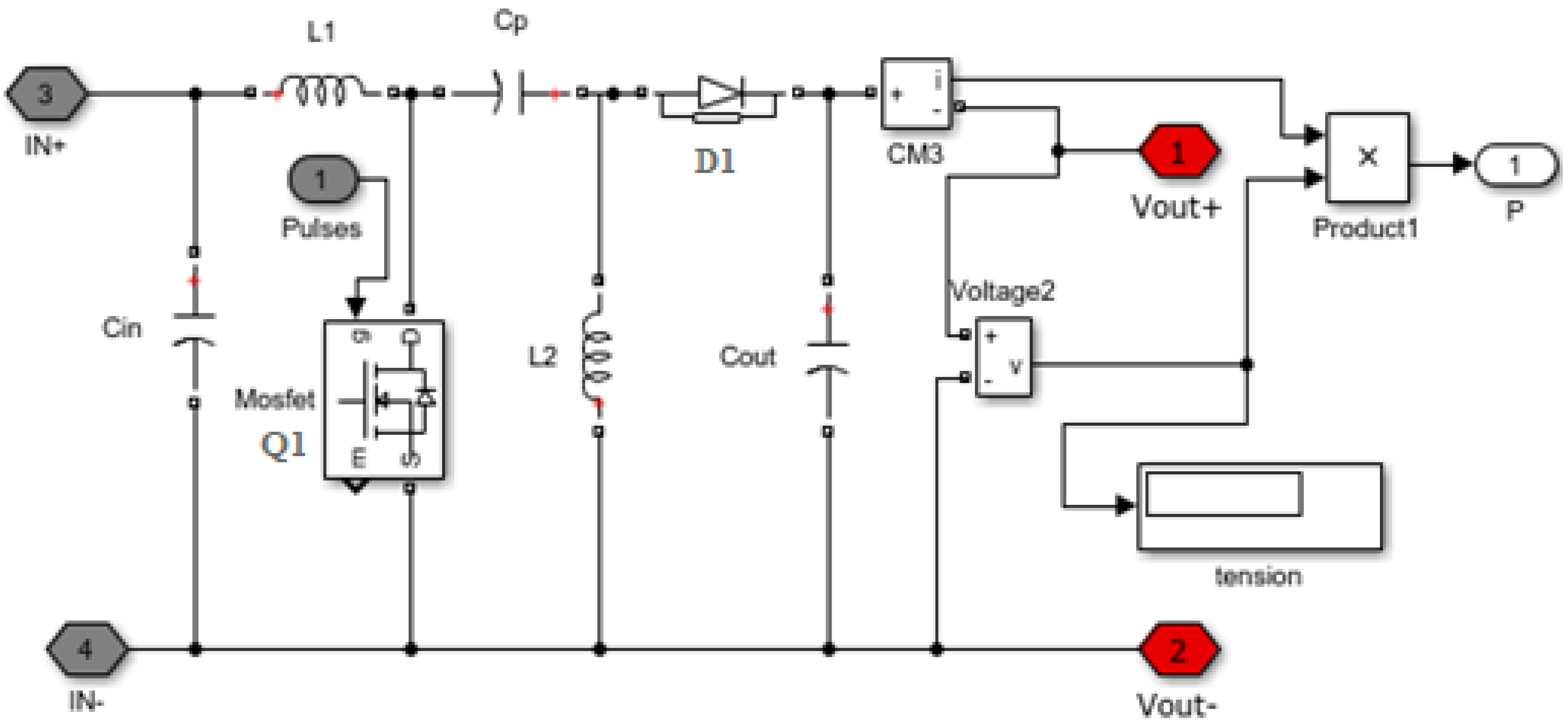
5.2.2. SEPIC Converter
- ;
- ; and
- .
5.2.3. DC/AC Inverter
5.3. Vector Control Optimized by Fuzzy Logic
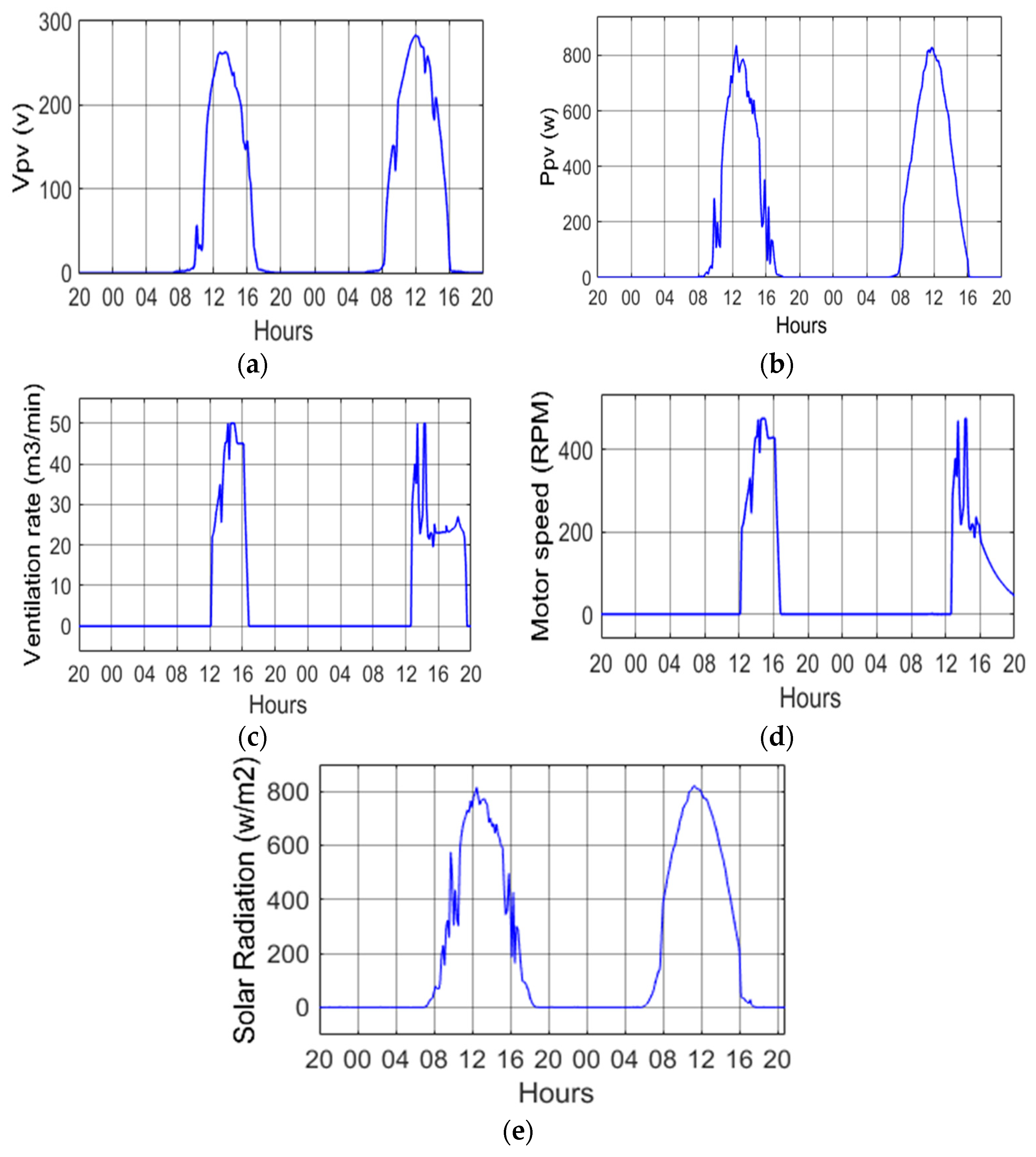
5.4. Simulations
6. Conclusions
Author Contributions
Funding
Conflicts of Interest
Nomenclature
| A | Surface of the greenhouse |
| Ca | Specific heat of air |
| Ce | Transfer coefficient of water vapor in the air |
| Ct | Thermal conductivity of the wooden plate |
| V | Volume |
| Vr | Ventilation rate |
| Hr | Heating rate |
| HuR | Humidification rate |
| DHuR | Dehumidification rate |
| C | Cover |
| ca | Canopy |
| Outside convection | |
| Wind speed | |
| Nh | Number of heaters |
| Rh | Capacity of heating |
| Pa | Vapor pressure |
| U | Overall heat transfer |
| S | Soil |
| Tsky | Sky temperature |
| Inf | Infiltration |
| Greek symbols | |
| α | Absorptivity of solar radiations |
| ρ | Reflectivity |
| Transmissivity | |
| Subscripts | |
| RPM | Revolution per minute |
| GPV | Photovoltaic generator |
| Ppv | PV power |
| Vpv | PV voltage |
| FL | Fuzzy Logic |
| MPPT | Maximum power-point tracking |
| P&O | Perturb and observe |
| Tin | Temperature inside greenhouse |
| Tout | Temperature outside greenhouse |
| Dehum | Dehumidifying |
| Hum | Humidifying |
| CRTEn | Research and Technology Center of Energy in Borj Cedria, Tunisia |
References
- Hahn, F. Fuzzy controller decreases tomato cracking in greenhouses. Comput. Elect. Agric. 2011, 77, 21–27. [Google Scholar] [CrossRef]
- Ben Ali, R.; Aridhi, E.; Mami, A. Fuzzy Logic Controller of temperature and humidity inside an agricultural greenhouse. In Proceedings of the 2016 7th International Renewable Energy Congress (IREC), Hammamet, Tunisia, 22–24 March 2016. [Google Scholar]
- Udinkten Cate, A.J. Modeling and (Adaptive) Control of Greenhouse Climates. Ph.D. Thesis, Agricultural University of Wageningen, Wageningen, The Netherlands, 1983. [Google Scholar]
- Liu, X.W.; Dai, T.F. Design for Fuzzy Decoupling Control System of Temperature and Humidity. In International Conference on Computer Science and Information Engineering; Springer: Berlin/Heidelberg, Germany, 2011; pp. 231–236. [Google Scholar]
- Fourati, F. Multiple neural control of a greenhouse. Neurocomputing 2014, 139, 138–144. [Google Scholar] [CrossRef]
- Taki, M.; Ajabshirchi, Y.; Ranjbar, S.F.; Rohani, A.; Matloobi, M. Heat transfer and MLP neural network models to predict inside environment variables and energy lost in a semi-solar greenhouse. Energy Build. 2016, 110, 314–329. [Google Scholar] [CrossRef]
- Hasni, A.; Taibi, R.; Draoui, B.; Boulard, T. Optimization of greenhouse climate model parameters using particle swarm optimization and genetic algorithms. Energy Procedia 2011, 6, 371–380. [Google Scholar] [CrossRef] [Green Version]
- Ji, R.; Qi, L.; Huo, Z. Design of Fuzzy Control Algorithm for Precious Irrigation System in Greenhouse. Nonlinear Model Predict. Control 2012, 370, 278–283. [Google Scholar]
- Lafont, F.; Balmat, J.F. Optimezd Fuzzy Control of a greenhouse. Fuzzy Sets Syst. 2002, 128, 47–59. [Google Scholar] [CrossRef]
- Atia, D.M.; El-madany, H.T. Analysis and design of greenhouse temperature control using adaptive neuro-fuzzy inference system. J. Electr. Syst. Inf. Technol. 2016, 4, 34–48. [Google Scholar] [CrossRef]
- Mohamed, S.; Hameed, I.A. A GA-based adaptive neuro-fuzzy controller for greenhouse climate control system. Alex. Eng. J. 2016, 57, 773–779. [Google Scholar] [CrossRef] [Green Version]
- Revathi, S.; Sivaku Maran, N. Fuzzy based temperature control of greenhouse. IFAC PapersOnLine 2016, 49, 549–554. [Google Scholar] [CrossRef]
- Azaza, M.; Echaieb, K.; Tadeo, F.; Fabrizio, E.; Iqbal, A.; Mami, A. Fuzzy Decoupling Control of Greenhouse Climate. Arab. J. Sci. Eng. 2015, 40, 2805–2812. [Google Scholar] [CrossRef]
- Dayan, J.; Dayan, E.; Strassberg, Y.; Presnov, E. Simulation and control of ventilation rates in greenhouses. Math. Comput. Simul. 2004, 65, 3–17. [Google Scholar] [CrossRef]
- Villarreal-Guerrero, F.; Kacira, M.; Fitz-Rodrıguez, E. Simulated performance of a greenhouse cooling control strategy with natural ventilation and fog cooling. Biosyst. Eng. 2012, 111, 217–228. [Google Scholar] [CrossRef]
- Boulard, T.; Draoui, B. Natural ventilation of a greenhouse with continuous roof vents: Measurements and data analysis. J. Agric. Eng. Res. 1995, 61, 27–36. [Google Scholar] [CrossRef]
- Esen, M.; Yuksel, T. Experimental evaluation of using various renewable energy sources for heating a greenhouse. Energy Build. 2013, 6, 340–351. [Google Scholar] [CrossRef]
- Abdel-Ghany, A.M.; Kozai, T. Dynamic modeling of the environment in a naturally ventilated, fog-cooled greenhouse. Renew. Energy 2006, 31, 1521–1539. [Google Scholar] [CrossRef]
- Fabrizio, E. Energy reduction measures in agricultural greenhouses heating: Envelope, systems and solar energy collection. Energy Build. 2012, 53, 57–63. [Google Scholar] [CrossRef]
- Azaza, M. Optimized Micro-Climate Controller of a Greenhouse Powered by Photovoltaic Generator. In Proceedings of the 2014 5th International Renewable Energy Congress (IREC), Hammamet, Tunisia, 25–27 March 2014. [Google Scholar]
- Echaieb, K.; Azaza, M.; Mami, A. A new control strategy of indoor air temperature in a photovoltaic greenhouse. Int. J. Soft Comput. Softw. Eng. 2013, 3, 848–852. [Google Scholar]
- Vergura, S.; Massi Pavan, A. On the photovoltaic explicit empirical model: Operations along the current-voltage curve. In Proceedings of the IEEE-ICCEP 2015 International Conference on Clean Electrical Power, Taormina, Italy, 16–18 June 2015. [Google Scholar]
- Massi Pavan, A.; Vergura, S.; Mellit, A.; Lughi, V. Explicit empirical model for photovoltaic devices. Experimental validation. Sol. Energy 2017, 155, 647–653. [Google Scholar] [CrossRef] [Green Version]
- Acciani, G.; Falcone, O.; Vergura, S. Analysis of the thermal heating of poly-Si and a-Si photovoltaic cell by means of FEM. Renew. Energy Power Qual. J. 2010, 8. [Google Scholar] [CrossRef]
- Vergura, S.; Marino, F. Quantitative and Computer Aided Thermography-based Diagnostics for PV Devices: Part I—Framework. IEEE J. Photovolt. 2017, 7, 822–827. [Google Scholar] [CrossRef]
- Vergura, S.; Colaprico, M.; de Ruvo, M.F.; Marino, F. A Quantitative and Computer Aided Thermography-based Diagnostics for PV Devices: Part II—Platform and Results. IEEE J. Photovolt. 2017, 7, 237–243. [Google Scholar] [CrossRef]
- Vergura, S.; Marino, F.; Carpentieri, M. Processing Infrared Image of PV Modules for Defects Classification. In Proceedings of the International Conference on Renewable Energy Research and Applications (ICRERA), Palermo, Italy, 22–25 November 2015. [Google Scholar]
- Ben Ali, R.; Bouadila, S.; Mami, A. Development of a Fuzzy Logic Controller applied to an agricultural greenhouse experimentally validated. Appl. Therm. Eng. 2018, 141, 798–810. [Google Scholar] [CrossRef]
- Echaieb, K.; Marouani, R.; Mami, A. Nonlinear multivariable design control strategy of solar water pumping system. Eur. J. Sci. Res. 2012, 72, 539–548. [Google Scholar]
- Chaouali, H.; Othmani, H.; Mezghani, D.; Jouini, H.; Mami, A. Fuzzy logic control scheme for a 3 phased asynchronous machine fed by Kaneka GSA-60 PV panels. In Proceedings of the 7th IEEE International Conference on Renewable Energy Congress, Hammamet, Tunisia, 22–24 March 2016. [Google Scholar]
- Mezghani, D.; Othmani, H.; Mami, A. Bond graph modeling and robust control of a photovoltaic generator that powered an induction motor pump via SEPIC converter. Int. Trans. Electr. Energy Syst. 2019, 29, e2746. [Google Scholar] [CrossRef]
- Azaza, M.; Echaieb, K.; Fabrizio, E.; Iqbal, A.; Mami, A. An intelligent system for the climate control and energy savings in agricultural greenhouses. Energy Effic. 2016, 9, 1241–1255. [Google Scholar] [CrossRef]


| Temperature Error | Ventilation Rate | Heating Rate |
|---|---|---|
| Negative big | High | Zero |
| Negative medium | Medium | Zero |
| Zero | Zero | Zero |
| Positive medium | Zero | Medium |
| Positive big | Zero | High |
| Humidity Error | Humidification Rate | Dehumidification Rate |
|---|---|---|
| Negative big | Zero | High |
| Negative medium | Zero | Medium |
| Zero | Zero | Zero |
| Positive medium | Medium | Zero |
| Positive big | High | Zero |
| Electrical Data | Value |
|---|---|
| Nominal output Pmpp (W) | 60 |
| Nominal voltage Vmpp (V) | 67 |
| Nominal current Impp (A) | 0.9 |
| Open-circuit voltage Voc (V) | 92 |
| Short-circuit current Isc (A) | 1.19 |
© 2020 by the authors. Licensee MDPI, Basel, Switzerland. This article is an open access article distributed under the terms and conditions of the Creative Commons Attribution (CC BY) license (http://creativecommons.org/licenses/by/4.0/).
Share and Cite
Riahi, J.; Vergura, S.; Mezghani, D.; Mami, A. Intelligent Control of the Microclimate of an Agricultural Greenhouse Powered by a Supporting PV System. Appl. Sci. 2020, 10, 1350. https://doi.org/10.3390/app10041350
Riahi J, Vergura S, Mezghani D, Mami A. Intelligent Control of the Microclimate of an Agricultural Greenhouse Powered by a Supporting PV System. Applied Sciences. 2020; 10(4):1350. https://doi.org/10.3390/app10041350
Chicago/Turabian StyleRiahi, Jamel, Silvano Vergura, Dhafer Mezghani, and Abdelkader Mami. 2020. "Intelligent Control of the Microclimate of an Agricultural Greenhouse Powered by a Supporting PV System" Applied Sciences 10, no. 4: 1350. https://doi.org/10.3390/app10041350