Article

Comparison of Selected Parameters of a Planetary Gearbox with Involute and Convex–Concave Teeth Flank Profiles

1
Department of Design and Machine Elements, Faculty of Mechanical Engineering, University of Zilina, Univerzitna 1, 010 26 Zilina, Slovakia
2
Faculty of Production Engineering, University of Life Sciences in Lublin, Głęboka 28, 20-612 Lublin, Poland
3
Department of Automatic Control and Robotics, Faculty of Electrical Engineering, Automatics, Computer Science and Biomedical Engineering, AGH University of Science and Technology in Krakow, Al A Mickiewicza 30, PL-30059 Krakow, Poland
*
Author to whom correspondence should be addressed.
Appl. Sci. 2020, 10(4), 1417; https://doi.org/10.3390/app10041417
Submission received: 6 December 2019 / Revised: 14 January 2020 / Accepted: 16 February 2020 / Published: 20 February 2020
(This article belongs to the Section Mechanical Engineering)

Abstract

:
This article presents a model of the geometry of teeth profiles based on the path of contact definition. The basic principles of the involute and convex–concave teeth profile generation are described. Due to the more difficult manufacturing of the convex–concave gear profile in comparison to the involute one, an application example was defined that suppressed this disadvantage, namely a planetary gearbox with plastic-injection-molded gears commonly used in vehicle back-view mirror positioners. The contact pressures and the slide ratios of the sun, planet, and ring gears with both teeth profile variants were observed and the differences between the calculated parameters are discussed.

1. Introduction

The main contribution of this article is the analysis of the convex–concave teeth flanks used by a common mechanism broadly used in the automotive industry to show the potential of the small change of the tooth flank spline to the parameters influencing the service life of the gearbox (contact pressures, specific slide ratios) and the quality of the teeth contact (contact ratio). The research presents the results of the performed calculations for small external module and especially the internal gears, which had not yet been published. The application of the convex–concave gear teeth flanks in the reduced planetary gearbox design is not yet known.
Smaller size gear arrangements of various plastic materials are becoming widespread due to their properties, such as wear resistance during dry running, low noise emission, good vibration damping, low inertia, low production costs, etc. Plastic gearboxes can be suitable for mass production in terms of production and manufacturing processes, where can be formed with other parts as one body, and they have outstanding functional features in terms of vibration reduction, low tare weight, and good corrosion resistance [1]. However, they display temperature-related problems, such as a rapidly decreasing load, thermal expansion, and the accuracy of formed gear parts. Therefore, the challenge to overcome is the production of gears with sufficient accuracy and durability such that they can be used in modern mechatronic applications in the automotive industry, medical equipment, electronics, and many other industries [2]. The selection of the right production structure is the key element in the design process of any production system because the structure used has long-term consequences for the efficiency, productivity, and operational costs of the designed system [3].
Planetary gears are widely used in aerospace applications, including space manipulators and satellite antenna propulsion mechanisms [4]. Rotating machine parts, such as shafts, bearings, and gears, are subject to a deterioration of performance, which if left unattended, may lead to failure or damage to the entire system [5]. Typical gear faults include chipped teeth, tooth breakages, root cracks, wear, pitting, and surface damage [6]. These forms of failure can lead to system imbalances and deterioration of the machining precision [7]. The presence of many faults in transmissions generates difficulties in their proper diagnosis. Diagnostics of these systems focus on digital signal processing (DSP) technologies, including the analysis of time (statistical) and frequency (spectral) domains [8]. Many researchers use methods such as Fourier and wavelet transforms [7,9,10], as well as Hilbert transforms (HTs) [11,12] or neural networks [13], to detect defects and operational parameters in rotating systems. These methods give quick results, but they do not allow for easy retrieval of information hidden in noisy or non-stationary time series. The application of recurrence plots analysis seems to be adequate for obtaining additional information coming from measurements [14]. Therefore, the identification of faults in gears has become an important subject of extensive research over the past decade [7,9,10,15]. In addition, the issues of wear mechanisms of mechanical systems of vehicles and combustion engines, as well as transmissions, are still an important issue. Many researchers show interest in damage to rotary units, such as turbochargers [16], kinematic pairs of charge exchange systems in combustion engines [17,18,19], injection systems [19,20,21,22,23], diesel engine [24,25,26,27], and the reliability of various types of gears [6,7,13,15,28].
The main advantage of the convex–concave gears is the lowering of the contact pressure using teeth flank meshing and the lowering of the slide ratios compared to involute gears [29]. The research shows that the scoring resistance of tooth flanks can be significantly raised by using special convex–concave profiles in plain tooth gears [30].
The S-gear tooth flank profile features a concave shape in the lower part of the dedendum such that the mating gears exhibit the convex–concave contact in the vicinity of the contact start and contact end. The shape of the tooth surface of the S-gear also provides higher comparative reduced-curvature radii. Therefore, the contact load is lower [31].
Tests were performed, which led to the confirmation of the assumption that the theoretical tooth flank geometry of S-gears provides more rolling and less sliding between the matching flanks compared to involute gears. The convex–concave contact leads to lower contact stress, which in combination with less sliding, means lower losses due to sliding friction, and consequently, less heat generated [32].
The S-gears were also used by the design of the planocentric gear boxes and devices for large transmission ratios, primarily applied in automation and mechatronic industry, which decrease rotational movement and increase torque to the largest possible extent in the smallest available space [33].
In all applications where the reduction gear must be as small as possible, a planetary gearset is preferred as it has the additional advantage of the input and output shafts being coaxial. The Wolfrom gear is suitable for high speed ratios, and has an efficiency that is not optimal but still acceptable. The version with single-rim satellites has significant design and technological advantages, such as large kinematic capabilities starting with speed ratios of about 50, but displaying a decreasing efficiency with a speed ratio increase. A high grade of compactness is achieved due to internal meshing and planet positioning inside of ring gears. If one-rim planets are used, the manufacturing is greatly simplified, especially by using the carrier-less arrangement [34].
Polymer material are, among others, largely used for the manufacturing of automotive parts, electrical and electronic equipment, and equipment in other industries. The most widely used polymer materials are: polyurethane (PUR), polypropylene (PP), acrylonitrile butadiene styrene (ABS), polyamides (PA), polycarbonate (PC), polyvinyl chloride (PVC), poly(phenylene oxide) (PPO), polyethylene terephthalate (PBT), polyacetal (POM), etc. [35,36,37]. In addition, polymer composites can be used for various parts of a vehicle body or, for example, gearbox housings [38,39,40,41].
Injection molding is the most extensively used process for manufacturing plastic gears. It has the capability to produce good-quality, small, nonmetallic gears of various geometries for light-load and noiseless transmissions. Nylon, acetal, polycarbonate, and polyester types of thermoplastic materials are commonly processed using injection molding to make gears. Various additives, such as polytetrafluoroethylene (PTFE), silicon, molybdenum disulfide, and graphite, are also added to improve the strength, inherent lubricity, heat stability, impact and wear resistance, and other properties of the thermoplastic materials [1,2,42]. Injection-molded parts, including gears, are manufactured by melting a specific powdered or pelletized polymer, or a combination thereof, before injection into a die containing the desired gear geometry of the gear. The full mechanical properties of the polymer and functionality of the gear is then realized via subsequent cooling, solidification, and ejection from the die and final trimming, if required [43]. The POM-C and PA66 materials are often used in plastic gear manufacturing because of the good dynamic friction coefficient values and the price criterion [31]. As an example of a typical plastic material used for gears, BASF Ultramid A3K (PA66) provides an easy flowing injection molding grade for fast processing and is commonly used in highly stressed technical parts, such as bearings and gear wheels.
The convex–concave gearing manufacturing methods and the demands on the gear axes position precision handicap this type of teeth flank relative to the involute ones. Thus, the calculation of the selected geometrical parameters and the contact pressure and slide ratios between the teeth flanks of the involute and convex–concave gearing are described using an example of a reduced planetary gearbox (Wolfrom stage) with plastic injection molded gears commonly used in vehicle back-view mirror positioners, which should show the comparison of both teeth flank type parameters with comparable manufacturing and operation demands.

2. Geometry of the Teeth Flanks

The mathematical model of convex–concave gearing is the base of the geometry model calculation and it is described in detail in Veres et al. [44]. The deterministic and probabilistic methods used in the determination of correct mating cylindrical teeth profiles was described in Harman et al. [29]. The determination of the geometric parameters of the gears’ teeth flanks is based on the equations evaluated using the shape of the path of contact. The general path of contact starting at point A and ending at the point E of this type of gearing is presented in Figure 1 [45].
The arcs of the path of contact are circular arcs defined by their radii rAC for the part of the contact path defined using the arc AC and rCE for the part of the contact path defined by the arc CE. The arc centers SAC and SCE are set by the coordinates xAC1 and yAC1, and xCE2 and yCE2, respectively. The points A and E define the end points of the path of contact. The geometric parameters affecting the relation between the pressure angle at various points of the path of contact α and the angle of the gear rotation between pressure angles of two arbitrary points ϕ(α) are shown in Figure 2.
The dependence of the characteristic teeth flank angles is described in Equation (1):
φ A C ,   C E = ± 2 r A C ,   C E r 1 [ ( α A C ,   C E α C ) cos α C + sin α C ln cos α C cos α A C ,   C E ] .
The signs are defined as positive (+) for the part of the contact path defined by the arc AC and as negative (−) for the part of the contact path defined by the arc CE.
The parametric equations of the gear tooth flank profiles coordinates obtained by the transformation of the path of contact coordinates made up of two circular arcs AC and CE, which are defined according [44] to the alternated equations:
x = 2 r A C ,   C E sin ( α A C ,   C E α C ) cos [ α A C ,   C E + φ A C ,   C E ( α A C ,   C E ) ] + r 1 sin φ A C ,   C E ( α A C ,   C E ) ,
y = ± 2 r A C ,   C E sin ( α A C ,   C E α C ) sin [ α A C ,   C E + φ A C ,   C E ( α A C ,   C E ) ] + r 1 sin φ A C ,   C E ( α A C ,   C E ) .
The x and y coordinates of the teeth flank curves are defined in the coordination systems with the origin at the points O1 or O2 for each coordinate system, respectively. The division of the contact path into parts divided into circular arcs AC and CE requires the division of all geometric and other gear pair parameters to analogous parts, which is defined according to the corresponding parts of the contact path curve [45].
The presented geometric model is also usable for the gears with involute flanks by putting the radii of the gear paths close to infinity. The performed calculations have already led to satisfactory results using the value of the path of contact arcs radii put into approximately 104 module multiples.

3. Reduced Planetary Gearbox Parameters

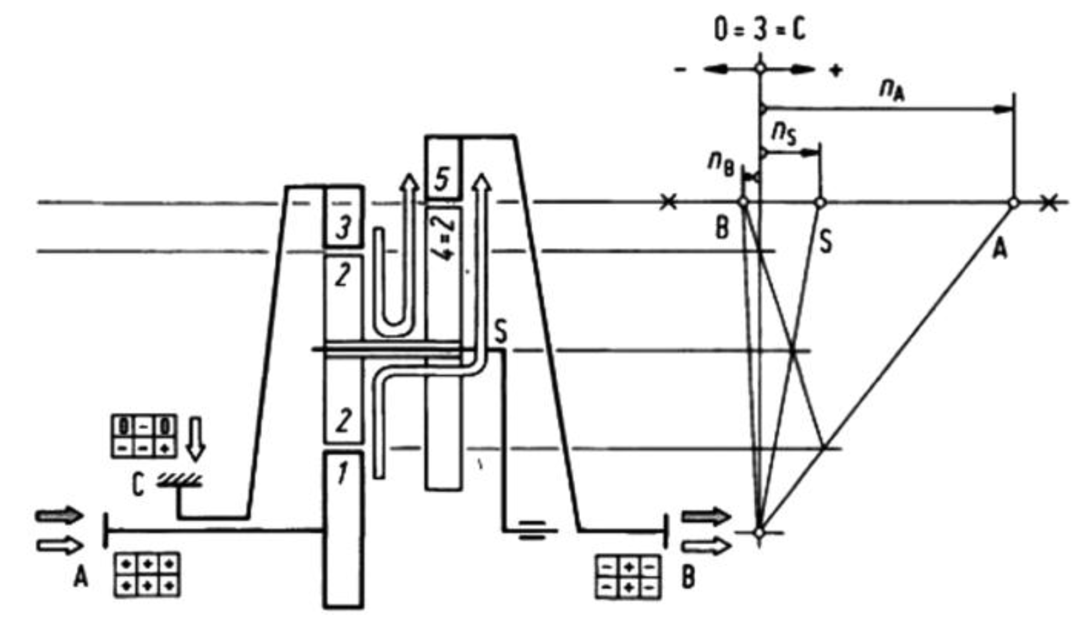
For the purpose of the comparison of selected parameters of planetary gears with involute and convex–concave gear profiles, a specific type of the gearbox was selected, namely a rear mirror positioner gearbox designed as a reduced Wolfrom stage (Figure 3). This type of the reduced planetary stage offers a high-speed reduction in a small built-in space and a satisfactory value for the torque ratio and gear contact efficiency.
The kinematic scheme of the gearbox is presented in Figure 4.
The gearbox had no carrier and had the same teeth number for gears 2 and 4. The axis distances of the planet gear 2 and ring gear 3, and for the planet gear 4 and the ring gear 5, had to be the same. Thus, the moduli ratio of the gear pairs 2-3 and 4-5 was defined by the following equation:
m 45 m 23 = z 3 z 2 z 5 z 4 = 51 18 48 18 = 1.1 .
Due to the defined value of the smaller module m23 = 0.45 mm, the module of the output part of the stage had to be m45 = 0.5 mm. The teeth number and the moduli of the gearbox gears are defined in Table 1.
The overall gearbox ratio was defined as [47]:
i = i 035 i 015 i 035 1 = 0.9412 ( 3.2 ) 0.9412 1 = 70.4 .
The partial stood gear stage II ratio i035 was defined as:
i 035 = + z 5 z 2 z 4 z 3 = 48 × 18 18 × 51 = 0.9412 .
The partial stood gear stage III ratio i015 was defined as:
i 015 = z 5 z 2 z 4 z 1 = 48 × 18 18 × 15 = 3.2 .
Due to the proper calculation of the torques, the reduced planetary gearbox had to be divided into two planetary stages, which had an equivalent efficiency to the solved gearbox. For the researched case, the scheme for the torque calculation considering the gear contact efficiency between the internal and external gear pair is shown in Figure 5.
The stood gearbox efficiency were defined by considering the efficiency of the internal gear contact ηi = 0.99 and the efficiency of the external gear contact ηe = 0.98 according to the equations:
η 035 = η i η i = 0.99 × 0.99 = 0.9801 ,
η 015 = η e η i = 0.98 × 0.99 = 0.9702 .
The torque ratio was defined as [47]:
μ = T B T A = i 035 η 035 i 015 η 015 i 035 η 035 1 = 0.9412 × 0.9801 ( 3.2 ) × 0.9702 0.9412 × 0.9801 1 = 51.9269 .
The overall gearbox efficiency was calculated as:
η = μ i = 51.9269 70.4 = 0.7376 .
The relative speeds and the torques of the gearbox central elements were calculated using the relative input speed ωA = 1 and the relative input torque TA = 1. The results of the calculation presented in Table 2 were used for the contact pressures calculation.
The results show the power division using the equivalent two-stage gearbox scheme: about 94% of the power flowed from the sun gear 1 across the carriers S2 and S1 to the ring gear 5’, and just about 6% of the power flowed directly to the output ring gear 5” and then together to the output B.

4. Calculation of Planetary Gearbox Gear Pairs Parameters

The gear pairs 1-2, 2-3, and 4-5 were observed to calculate the contact pressures and slide ratios for the gear teeth with the standard involute geometry, as well as for the convex–concave gear teeth flanks.

4.1. Geometry

The gear stages moduli are defined as m23 = 0.45 mm and m45 = 0.5 mm. The pressure angle at the contact point C was defined by the value αC = 20°.
The ratio between the tooth addendum height ha and dedendum height hf of the involute external gears Re was defined considering the gearing module m as:
R e = h a h f = 1 m 1 , 25 m .
The ratio between the tooth addendum and dedendum height of the internal involute gears Ri was defined to prevent the interference between the planet teeth and ring gear tip surface as:
R i = h a h f = 0 , 8 m 1 , 25 m .
The geometry of the convex–concave teeth flanks depends on the value of the gear teeth module m, the number of the gear teeth z, the radii of the contact path arcs rAC and rCE and the pressure angle at the contact point C defined by the value αC. The convex–concave condition of the tooth flank curve describes the inequality [44]:
r A C ,   C E < z min m 4 cos α C = 15 × 0.45 4 cos 20 ° = 1.5857 mm .
The radii of the contact path arcs in the symmetric arrangement in the selected gear pair were defined as rAC = rCE = 1.5 mm, which satisfied the Inequality (14).

4.2. Contact Pressures

The Hertzian contact pressures at the tooth flanks of the pinion-gear contact point were calculated according the equation [45]:
p = Z E F 1 l ρ r e d .
The material coefficient ZE depends on the Young‘s moduli E1, E2 and the Poisson’s ratios μ1, μ2 of the pinion (indexed by 1) and gear (indexed by 2) material according the equation:
Z E = 1 π ( 1 μ 1 2 E 1 + 1 μ 2 2 E 2 ) .
The gears considered were made from Nylon 6.6 (PA66) with Poisson’s ratios of μ1 = μ2 = 0.42 [48] and average Young’s moduli of E1 = E2 = 2930 MPa [49].
The contact force was calculated by considering the relative torque values presented in Table 2 using the input torque of TA = 1 Nmm, the number of planet gears in each stage as λ = 3, and using the corresponding pressure angle α as:
F 1 = T 1 λ r 1 cos α .
The contact force values will vary according the input torque according to the particular choice of the electric motor. The width of every gear flank was set to l = 1.5 mm.
The reduced radius of the teeth flank curvature ρred was calculated according the radii of curvature of the pinion ρ1 and the gear ρ2 using the equation:
ρ r e d = ρ 1 ρ 2 ρ 1 + ρ 2 .

4.3. Specific Sliding Ratios

The specific sliding ratio is a contact severity parameter that is a dimensionless ratio that is dependent on the tooth geometry and independent of the pitch line velocity. It is positive in addenda, ranging from zero at the pitch point to +1 at the interference point of the mating gear, and negative in dedenda, ranging from zero at the pitch point to −∞ at the interference point. Generally, vss1 < 1.0 is recommended, and vss1 < 0.5 is preferred, for good resistance to macro pitting, micro pitting, and scuffing [50].
The slide ratio is defined according to decomposition of the velocity vector into two directions: a normal and tangential relative to the surface of contact. The gap between the rolling velocity of the pinion vr1 and the gear vr2 defines the sliding velocity for the pinion vs1 and the gear vs2, as well as the specific sliding ratios vss1 and vss2 according the equations [50]:
v s s 1 = v s 1 v r 1 = v r 1 v r 2 v r 1 ,
v s s 2 = v s 2 v r 2 = v r 2 v r 1 v r 2 .
The sliding ratio of the partial gear pairs of the Wolfrom stage were calculated for the relative pinion speed ωpinion = 1 and the gear teeth numbers defined in Table 1.

5. Discussion

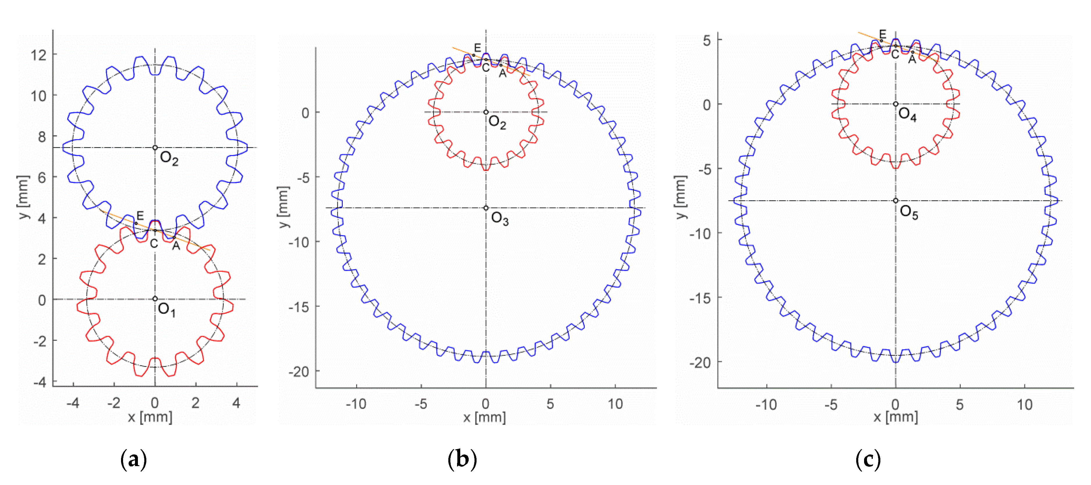
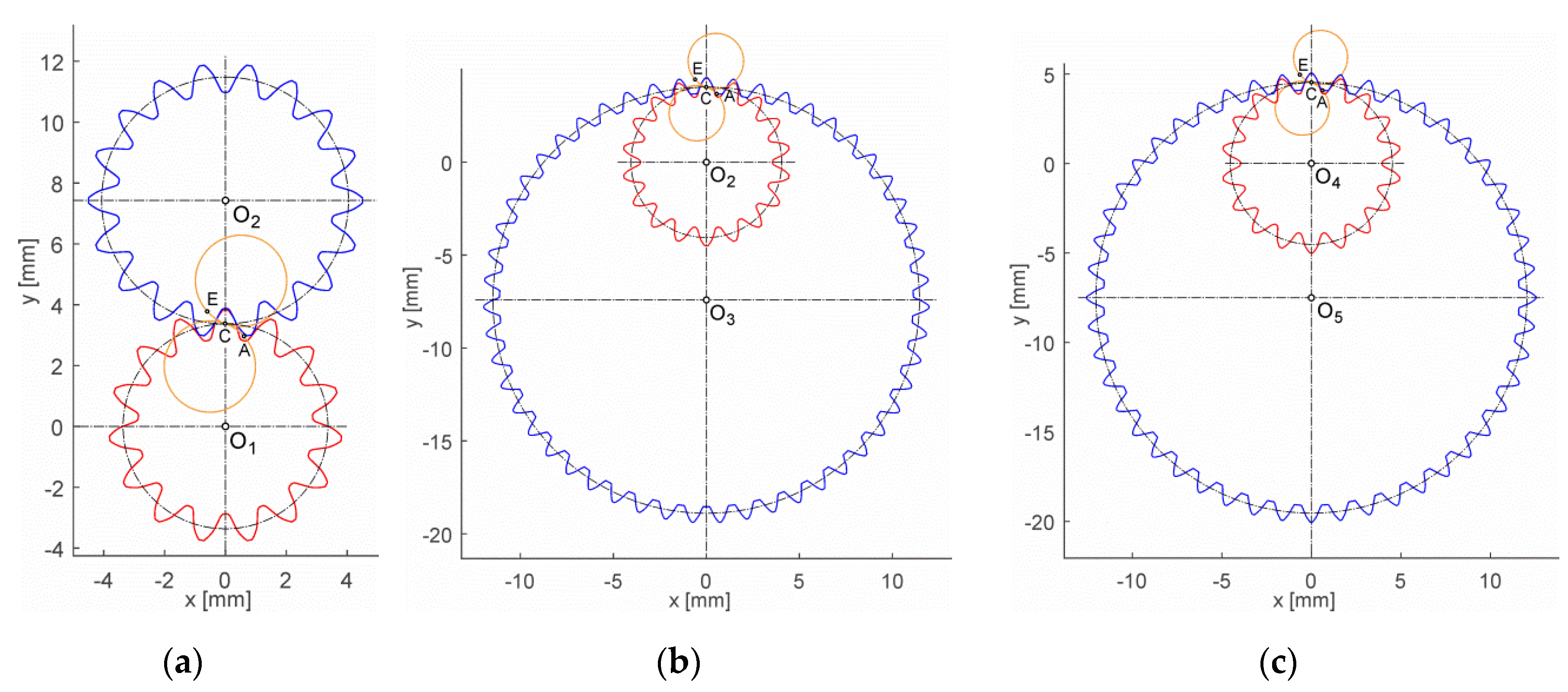
The geometry of the partial pinion-gear pairs of the Wolfrom stage gearbox are presented in Figure 6 for the involute teeth flanks and in Figure 7 for the convex–concave teeth flanks.
The pinion center of each presented gear pair (O1, O2, O4) is defined in Figure 6a,b,c, as well as in Figure 7a,b,c using the coordinates x = 0 and y = 0. The diameters of the addendum and dedendum circle is the same in both cases. The involute teeth flanks’ path of contact is represented in Figure 6 by the lines declined by the pressure angle αw = 20° passing through the pitch point C. The convex–concave teeth flanks path of the contact is represented in Figure 7 using circles, whose parts belong to the path of contact consisting of two circular arcs tangentially connected at the pitch point C. The pressure angle, which varies along the path of contact, takes on the value αC = 20° at the pitch point C lying on the pinion and gear centers’ link. The points A and E represent the start and end point of the path of contact.
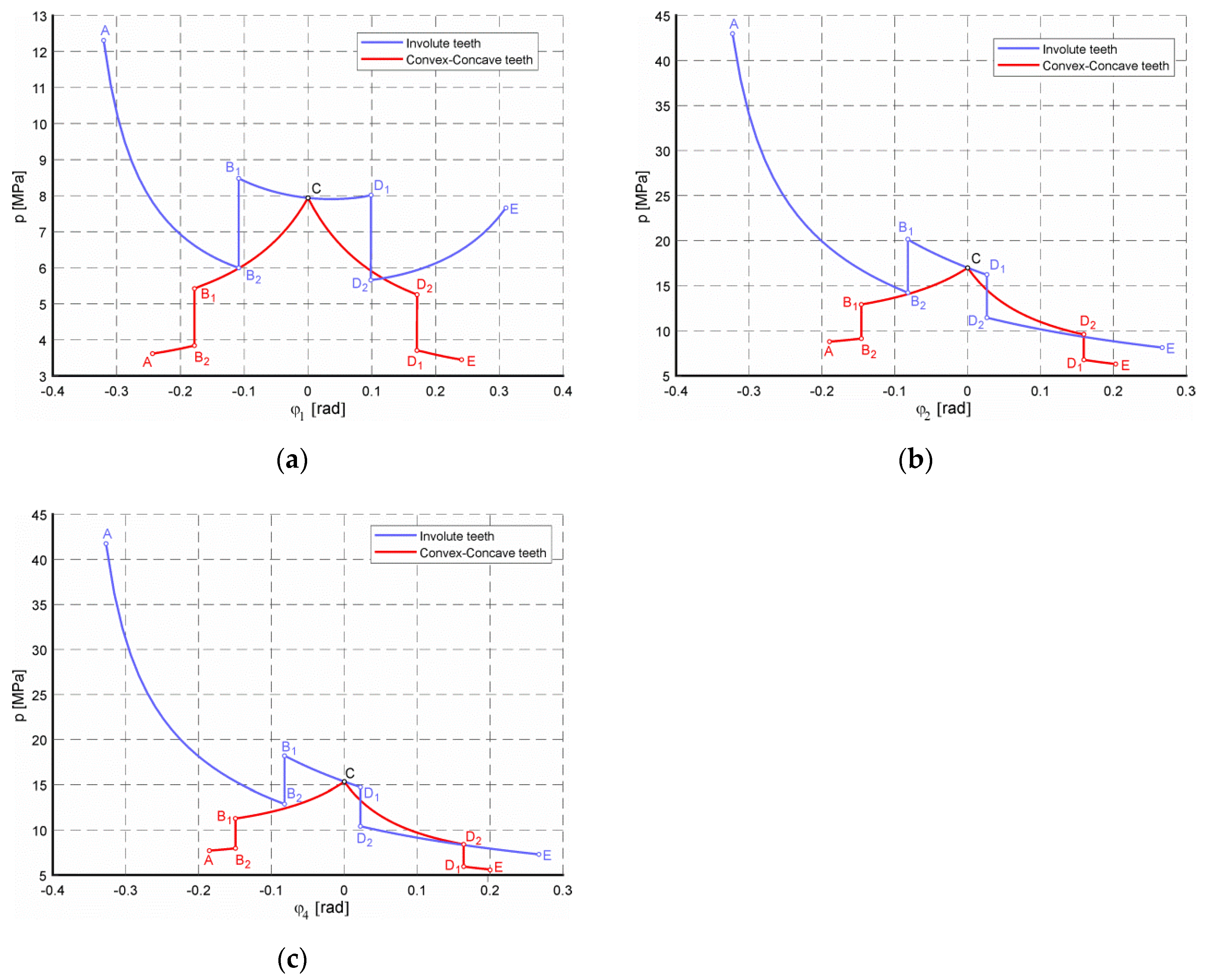
The contact Hertzian pressure p at the teeth flanks of the partial pinion-gear pairs depends on the angle of the pinion rotation ϕpinion between the pressure angles of two arbitrary points (A–E), which is shown in Figure 8 for the involute and convex–concave teeth flanks.
The gear pair contact pressures dropped by the convex–concave teeth flanks are shown in Figure 8 and Table 3, where the values of the contact pressures are described in detail. The points A and E represent the start and the end of the contact path, the points B and D represent the start and the end of the single pair teeth engagement (indexed with 1 for the single and 2 for the double pair engagement), and the point C represents the pitch contact point lying on the gear pair centers’ link. Table 3 also presents the flank type contact pressure ratio pC-C/pINV between the convex–concave (pC-C) and the involute (pINV) teeth flanks values.
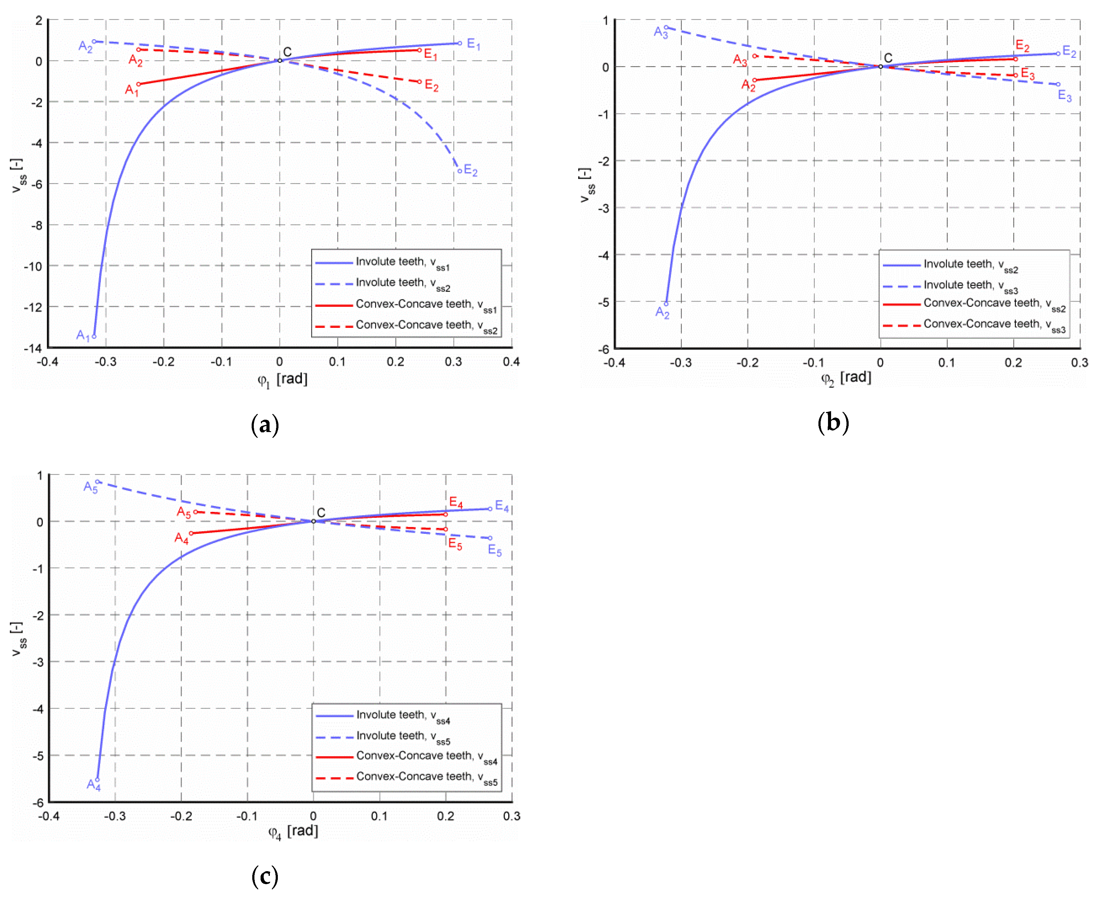
The specific sliding ratios vss of the partial pinion-gear pairs that depend on the angle of the pinion rotation ϕpinion between the pressure angles of two arbitrary points (A–E) are shown in Figure 9 for the involute and the convex–concave teeth flanks.
The gear pair specific sliding ratios of the convex–concave teeth flanks dropped significantly, as shown in Figure 9 and Table 4, where the values of the slide ratios are described in detail. The points A and E represent the start and end of the contact path (indexed with 1, 2, and 4 for the pinion and 2, 3, and 5 for the gear), and point C represents the pitch contact point lying on the gear pair centers’ link. Table 4 also presents the flank type slide ratio vssC-C/vssINV between the convex–concave (vssC-C) and the involute (vssINV) teeth flank values.
The analysis of the involute gear teeth flank geometry of the observed gearbox led to the reduction of the tip diameters of the ring gears (Figure 6). The involute gear profile with the standard addendum and dedendum coefficients was used for the external gear pair 1-2, as well as for the internal gear pairs 2-3 and 4-5.
The contact pressures in the convex–concave gears were significantly lower than for the involute gears, especially for the gear pairs with internal gearing (Figure 8). The drop of the contact pressure was most significant for the gear pair 4-5 at the starting point of the path of contact A, where the pressure value in the convex–concave teeth flanks dropped to 18.47% of the value calculated for the involute teeth flanks (Table 3). The drop of the contact pressure was accompanied by the drop of the contact ratio, which had a value close to 1 for the convex–concave teeth flanks. The comparison of the contact ratio values εα using the involute and convex–concave teeth flanks in the observed gearbox are presented in Table 5.
Past research has shown the preferable sliding behavior of the convex–concave-shaped tooth flanks relative to the involute ones. The calculations were made just for the external gear pairs [51].
The most important features of polymeric S-gears, which were expected, were the lower sliding due to the relatively larger contact lengths of dedendum–addendum of a gear pair (and consequently lower friction and contact temperature); the convex–concave contact zones in the vicinity of meshing start and end; and the higher reduced radii of curvature, particularly in the meshing start and end zones [31].
The specific sliding ratio values of the calculated convex–concave teeth flanks were lower than the involute ones, as seen in the comparison in Figure 9. The gear pairs with involute teeth flanks showed a high value for the specific slide ratio due to high contact ratio. The lower contact ratio of the convex–concave teeth led to better behavior of the teeth flanks in terms of the wear and scoring resistance. The biggest drop of the specific slide ratio was also observed for the gear pair 4-5 at the starting point of the path of contact A, where the specific slide ratio value in the convex–concave teeth flanks of the pinion dropped to 4.66% of the value calculated for the involute teeth flanks (Table 4).

6. Conclusions

The article presents a possible method for modelling the involute and convex–concave gear teeth flanks based on the path of contact curves. Due to possibility of the comparison of various teeth flank shapes in terms of the selected parameters of the observed gearbox, a mathematical model of the gear teeth flanks geometry was built. The model was developed for the involute gear pairs with no correction and the convex–concave gear pairs with the path of contact consisting of two circular arcs.
Multiple variations of the convex–concave teeth flank parameters (module, addendum/dedendum height coefficients, path of contact radii, pressure angle in the pitch point C, Young moduli, and Poisson’s coefficients of the gear pair) allow for further research of their influence on the observed parameters of the gear pairs (contact pressures, specific sliding ratios, scoring resistance, etc.).
The presented parametric calculation model can be used as the pre-prototype solver of partial modifications of the involute and convex–concave gears, as well as the source of gear CAD (Computer Aided Design) model preparation for the STL (Standard Triangle Language) model building or FEM (Finite Elements Method) analyses.
The lower contact pressures and favorable sliding behavior of the convex–concave gear flanks against the involute ones led to the idea to use this type of teeth flank in the applications where the plastic involute gears are widely used at present. The micro-gearboxes with the gears molded from plastics allow for the utilization of lower contact pressures and favorable progress of the specific sliding with low manufacturing costs. The prototype of such a gearbox could also be built with the rapid prototyping technology methods using various commonly used plastic gear materials (PA6, PA66, POM, etc.) for tests according to the influence of the gear geometry parameter changes to the gearbox lifetime. The lower accuracy of the manufacturing process and its influence on the gears’ behavior is also an interesting problem for further research.

Author Contributions

Conceptualization, F.B.; methodology, F.B. and M.L.; formal analysis, F.B., M.L., and J.C.; resources, F.B., M.L., J.C., Z.K., and A.G.; writing—original draft preparation, F.B., M.L., J.C., Z.K., and A.G.; writing—review and editing, F.B., M.L., and J.C.; visualization, F.B., M.L., Z.K., and J.C.; funding acquisition, F.B. All authors have read and agreed to the published version of the manuscript.

Funding

The research was supported by the Cultural and Educational Grant Agency of the Ministry of Education, Science, Research and Sport of the Slovak Republic under the project No. 046ŽU-4/2018.

Conflicts of Interest

The authors declare no conflict of interest.

References

  1. Kim, G.H.; Lee, J.W.; Seo, T.I. Durability Characteristics Analysis of Plastic Worm Wheel with Glass Fiber Reinforced Polyamide. Materials 2013, 6, 1873–1890. [Google Scholar] [CrossRef] [Green Version]
  2. Hlebanja, G.; Kulovec, S.; Hlebanja, J.; Duhovnik, J. On endurance of the S-shaped plastic gears. Int. Conf. Power Transm. 2016, 79–86. [Google Scholar]
  3. Gola, A. Reliability analysis of reconfigurable manufacturing system structures using computer simulation methods. Eksploat. I Niezawodn. Maint. Reliab. 2019, 21, 90–102. [Google Scholar] [CrossRef]
  4. Chen, Z.; Shao, Y. Dynamic simulation of planetary gear with tooth root crack in ring gear. Eng. Fail. Anal. 2013, 31, 8–18. [Google Scholar] [CrossRef]
  5. Li, X.; Elasha, F.; Shanbr, S.; Mba, D. Remaining Useful Life Prediction of Rolling Element Bearings Using Supervised Machine Learning. Energies 2019, 12, 2705. [Google Scholar] [CrossRef] [Green Version]
  6. Kia, S.H.; Henao, H.; Capolino, G.A. Gear tooth surface damage fault detection using induction machine stator current space vector analysis. IEEE Trans. Ind. Electron. 2015, 62, 1866–1878. [Google Scholar] [CrossRef]
  7. Sun, W.; Yao, B.; Zeng, N.; Chen, B.; He, Y.; Cao, X.; He, W. An Intelligent Gear Fault Diagnosis Methodology Using a Complex Wavelet Enhanced Convolutional Neural Network. Materials 2017, 10, 790. [Google Scholar] [CrossRef] [Green Version]
  8. Ruqiang, Y.; Yuning, Q.; Zhoudi, H.; Gao, R.X. Rolling bearing defect severity evaluation using recurrence plot entropy. In Proceedings of the 2011 IEEE International Instrumentation and Measurement Technology Conference, Binjiang, China, 10–12 May 2011. [Google Scholar] [CrossRef]
  9. Jedliński, Ł.; Jonak, J. A disassembly-free method for evaluation of spiral bevel gear assembly. Mech. Syst. Signal Process. 2017, 88, 399–412. [Google Scholar] [CrossRef]
  10. Sawalhi, N.; Randall, R.B. Gear parameter identification in a wind turbine gearbox using vibration signals. Mech. Syst. Signal Process. 2014, 42, 368–376. [Google Scholar] [CrossRef]
  11. Karioja, K.; Lahdelma, S.; Litak, G.; Ambrożkiewicz, B. Extracting periodically repeating shocks in a gearbox from simultaneously occurring random vibration. In Proceedings of the 15th International Conference on Condition Monitoring and Machinery Failure Prevention Technologies, CM/MFPT 2018, Nottingham, UK, 10–12 September 2018; pp. 456–464. [Google Scholar]
  12. Soualhi, A.; Medjaher, K.; Zerhouni, N. Bearing health monitoring based on Hilbert-Huang transform, support vector machine and regression. IEEE Trans. Instrum. Meas. 2015, 64, 52–62. [Google Scholar] [CrossRef] [Green Version]
  13. Marichal, G.N.; Del Castillo, M.L.; López, J.; Padrón, I.; Artés, M. An Artificial Intelligence Approach for Gears Diagnostics in AUVs. Sensors 2016, 16, 529. [Google Scholar] [CrossRef] [Green Version]
  14. Ambrożkiewicz, B.; Meier, N.; Guo, Y.; Litak, G.; Georgiadis, A. Recurrence-based diagnostics of rotary systems. IOP Conf. Ser. 2019, 710, 012014. [Google Scholar] [CrossRef]
  15. Syta, A.; Jonak, J.; Jedliński, Ł.; Litak, G. Failure diagnosis of a gear box by recurrences. J. Vib. Acoust. 2012, 134, 41006. [Google Scholar] [CrossRef]
  16. Hadryś, D.; Bąkowski, H.; Stanik, Z.; Kubik, A. Analysis of shaft wear in turbocharges of automotive vehicles. Transp. Prob. 2019, 14, 85–95. [Google Scholar] [CrossRef] [Green Version]
  17. Bąkowski, H. Wear mechanism of spheroidal cast iron piston ring-aluminum matrix composite cylinder liner contact. Arch. Metall. Mater. 2018, 63, 481–490. [Google Scholar]
  18. Longwic, A.; Nieoczym, A.; Kordos, P. Evaluation of the combustion process in a spark-ignition engine based on the unrepeatability of the maximum pressure. IOP Conf. Ser. Mater. Sci. Eng. 2018, 421, 1–9. [Google Scholar] [CrossRef]
  19. Makareviciene, V.; Matijosius, J.; Pukalskas, S.; Vegneris, R.; Kazanceva, I.; Kazancev, K. The exploitation and environmental characteristics of diesel fuel containing rapeseed butyl esters. Transport 2013, 28, 158–165. [Google Scholar] [CrossRef]
  20. Balytskyi, A.; Abramek, K.F.; Stoeck, T.; Osipowicz, T. Diagnostic of degradation of the lock seal ring by the loss of combustion engine working gases. Mater. Sci. 2014, 50, 156–169. [Google Scholar] [CrossRef]
  21. Ignaciuk, P.; Gil, L. Damages to injectors in diesel engines. Adv. Sci. Technol. Res. J. 2014, 8, 58–61. [Google Scholar]
  22. Osipowicz, T.; Abramek, K.F.; Matuszak, Z.; Jaśkiewicz, M.; Ludwinek, K.; Poliak, M. The analysis of technical condition common rail fuel system components. In Proceedings of the 11th International Scientific and Technical Conference on Automotive Safety, Casta Papiernicka, Slovakia, 18–20 April 2018. [Google Scholar] [CrossRef]
  23. Szpica, D. Investigating fuel dosage non-repeatability of low-pressure gas-phase injectors. Flow Meas. Instrum. 2018, 59, 147–156. [Google Scholar] [CrossRef]
  24. Glos, J.; Sejkorova, M. Tribo-diagnostics as an indicator and input for the optimization of vehicles preventive maintenance. In Proceedings of the 11th International Conference on Intelligent Technologies in Logistics and Mechatronics Systems (ITELMS’2016), Panevezys, Lithuania, 28–29 April 2016; pp. 83–89. [Google Scholar]
  25. Sejkorova, M.; Hurtova, I. Engine oil analysis-effective instrument to evaluate reliability of tractor engines. In Proceedings of the 18th International Scientific Conference Engineering for Rural Development, Jelgava, Latvia, 22–24 May 2019; pp. 971–976. [Google Scholar]
  26. Stoeck, T.; Abramek, K.F. Application of the polynomial interpolation method for determining performance characteristics of a diesel engine. Metrol. Meas. Syst. 2014, 21, 157–168. [Google Scholar] [CrossRef]
  27. Tucki, K.; Mruk, R.; Orynycz, O.; Gola, A. The effects of pressure and temperature on the process of auto-ignition and combustion of rape oil and its mixtures. Sustainability 2019, 11, 3451. [Google Scholar] [CrossRef] [Green Version]
  28. Figlus, T. A method for diagnosing gearboxes of means of transport using multi-stage filtering and entropy. Entropy 2019, 21, 441. [Google Scholar] [CrossRef] [Green Version]
  29. Harman, B.N.; Opalic, M.; Veres, M. Deterministic and probabilistic methods in determination of correct mating cylindrical teeth profiles. Strojarstvo 2011, 53, 191–197. [Google Scholar]
  30. Veres, M.; Nemcekova, M.; Marinkovic, A. Tooth flanks scoring resistance of non-involute teeth profiles in plane toothed cylindrical gears. FME Trans. 2009, 37, 103–106. [Google Scholar]
  31. Hlebanja, G.; Hlebanja, J. S-gears: From Metal to Polymer Solution. In Advanced Gear Engineering; Goldfarb, V., Trubachev, E., Barmina, N., Eds.; Springer International Publishing Switzerland: Cham, Switzerland, 2018; pp. 255–269. [Google Scholar] [CrossRef]
  32. Zorko, D.; Kulovec, S.; Tavcar, J.; Duhovnik, J. Different teeth profile shapes of polymer gears and comparison of their performance. J. Adv. Mech. Des. Syst. Manuf. 2017, 11, 1–5. [Google Scholar] [CrossRef] [Green Version]
  33. Hlebanja, G.; Kulovec, S. Development of a Planocentric Gear Box Based on S-Gear Geometry. Kolloqu. Getr. Garch. 2015, 11, 205–216. [Google Scholar]
  34. Arnaudov, K.; Karaivanov, D.P. Planetary Gear Trains; CRC Press: Boca Raton, FL, USA; New York, NY, USA; Taylor & Francis Group: London, UK, 2019. [Google Scholar]
  35. Fiorio, R.; Diez, S.V.; Sánchez, R.; D’hooge, D.R.; Cardon, L. Influence of Different Stabilization Systems and Multiple Ultraviolet A (UVA) Aging/Recycling Steps on Physicochemical, Mechanical, Colorimetric, and Thermal-Oxidative Properties of ABS. Materials 2020, 13, 212. [Google Scholar] [CrossRef] [Green Version]
  36. García-Domínguez, D.; Claver, J.; Camacho, A.M.; Sebastián, M.A. Considerations on the Applicability of Test Methods for Mechanical Characterization of Materials Manufactured by FDM. Materials 2020, 13, 28. [Google Scholar] [CrossRef] [Green Version]
  37. Gardyński, L.; Lonkwic, P. Testing polymer rollers memory in the context of passenger lift car comfort. J. Vibroeng. 2014, 16, 225–230. [Google Scholar]
  38. Borazjani, S.; Belingardi, G. Development of an innovative design of a composite-sandwich based vehicle roof structure. Compos. Struct. 2017, 168, 522–534. [Google Scholar] [CrossRef]
  39. Krzyżak, A.; Kucharczyk, W.; Gaska, J.; Szczepaniak, R. Ablative test of composites with epoxy resin and expanded perlite. Compos. Struct. 2018, 202, 978–987. [Google Scholar] [CrossRef]
  40. Krzyżak, A.; Valis, D. Selected reliability measures of composites with natural fibres tested in climatic environment. In Proceedings of the International Conference on Military Technologies (ICMT 2015), Brno, Czech, 19–21 May 2015; pp. 81–87. [Google Scholar]
  41. Pieniak, D.; Wit-Rusieck, A.M.; Krzyżak, A.; Gil, L.; Krzysiak, Z. Adhesion tests of varnish coatings used on the surface of carbon fiber reinforced polimer compositions. Przemysł Chem. 2019, 98, 1619–1622. [Google Scholar]
  42. Jiang, R.; Liu, T.; Xu, Z.; Park, C.B.; Zhao, L. Improving the Continuous Microcellular Extrusion Foaming Ability with Supercritical CO2 of Thermoplastic Polyether Ester Elastomer through In-Situ Fibrillation of Polytetrafluoroethylene. Polymers 2019, 11, 1983. [Google Scholar] [CrossRef] [PubMed] [Green Version]
  43. Gupta, K.; Jain, N.; Laubscher, R. Advanced Gear Manufacturing and Finishing; Academic Press: Cambridge, MA, USA, 2017. [Google Scholar]
  44. Veres, M.; Bosansky, M.; Gadus, J. Theory of Convex-Concave and Plane Cylindrical Gearing; Slovak University of Technology: Bratislava, Slovak, 2006. [Google Scholar]
  45. Brumercik, F.; Lukac, M.; Majchrak, M.; Krzysiak, Z.; Krzywonos, L. Teeth geometry and contact pressure calculation of external cycloidal gears. Sci. J. Sil. Univ. Technol. Ser. Transp. 2018, 101, 27–35. [Google Scholar] [CrossRef]
  46. Wikimedia Commons. Available online: https://commons.wikimedia.org/wiki/File:Rearview_Mirror_Epicyclic_Gears.jpg (accessed on 1 June 2019).
  47. Looman, J. Zahnradgetriebe. Grundlagen, Konstruktionen, Anwendungen in Fahrzeugen; Springer: Berlin/Heidelberg, Germany, 1996. [Google Scholar]
  48. Polymer Science. Typical Poisson’s Ratios of Polymers at Room Temperature. Available online: https://polymerdatabase.com/polymer%20physics/Poisson%20Table.html (accessed on 1 June 2019).
  49. MatWeb. Overview of Materials for Nylon 6, Cast. Available online: http://matweb.com/search/DataSheet.aspx?MatGUID=8d78f3cfcb6f49d595896ce6ce6a2ef1 (accessed on 1 June 2019).
  50. Erichello, R. Gear Sliding. In Encyclopedia of Tribology; Wang, Q.J., Chung, Y.-W., Eds.; Springer: Boston, MA, USA, 2013. [Google Scholar] [CrossRef]
  51. Orokocky, R.; Bosansky, M.; Veres, M. The influence of geometrical parameter to sliding speed in K-K gears. In Proceedings of the 44th Conference of the Departments of Machine Elements and Mechanisms, Prague, Czech Republic, 9–10 September 2003; pp. 240–243. [Google Scholar]
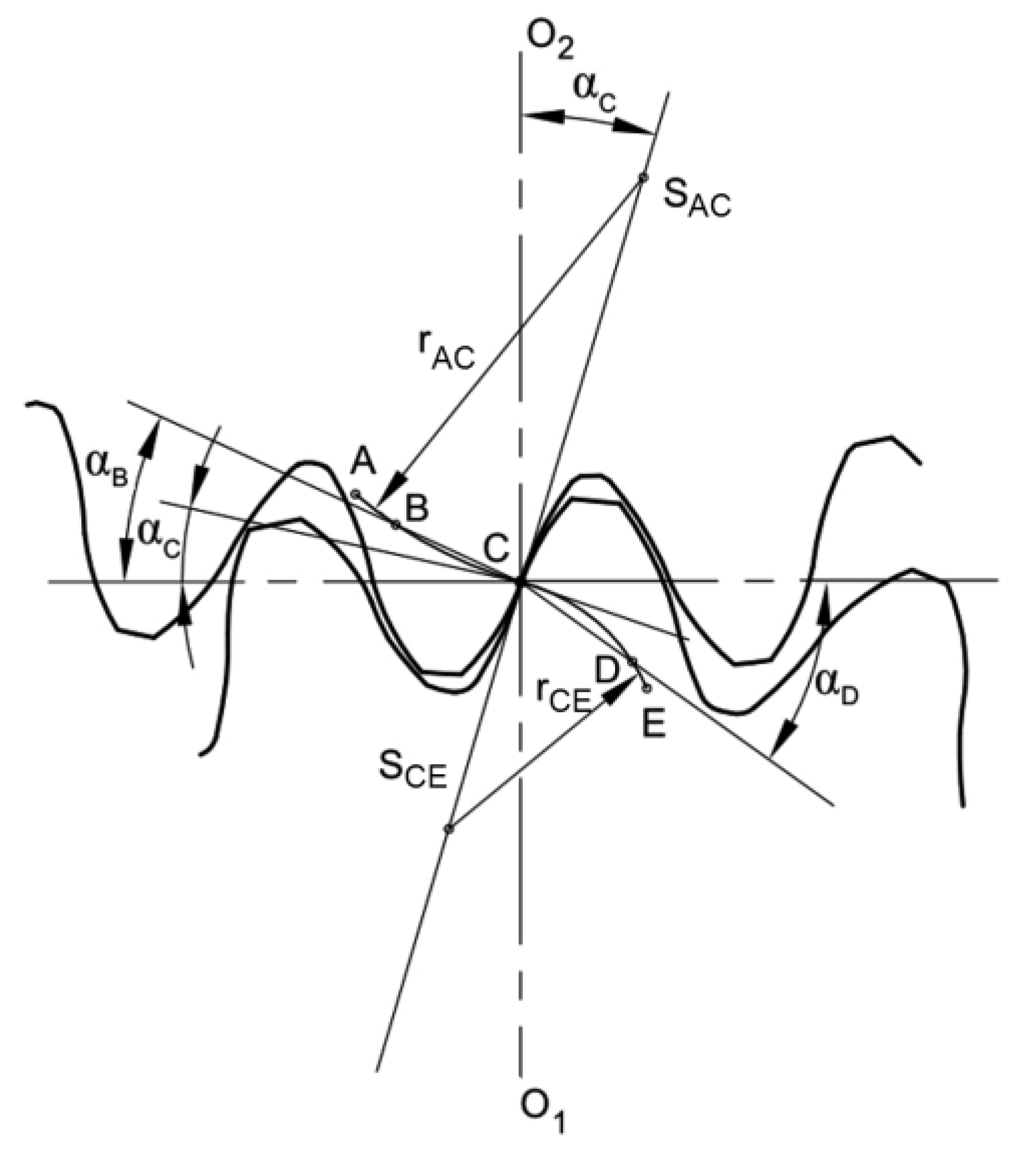
Figure 1. Characteristic points and geometric parameters of the convex–concave gearing.
Applsci 10 01417 g001
Figure 2. Relation between the angles α and ϕr: 1—path of contact, 2—tooth flank profile, and 3—tooth flank profile evolute.
Applsci 10 01417 g002
Figure 3. Rear-view mirror drive gearbox, reproduced from [46].
Applsci 10 01417 g003
Figure 4. Kinematic scheme of the Wolfrom stage gearbox.
Applsci 10 01417 g004
Figure 5. Equivalent efficiency scheme of the Wolfrom stage gearbox.
Applsci 10 01417 g005
Figure 6. Geometric models of the gear pairs with involute teeth flanks: (a) gear pair 1-2, (b) gear pair 2-3, and (c) gear pair 4-5.
Applsci 10 01417 g006
Figure 7. Geometric models of the gear pairs with convex-concave teeth flanks: (a) gear pair 1-2, (b) gear pair 2-3, and (c) gear pair 4-5.
Applsci 10 01417 g007
Figure 8. Hertzian pressure p, which depends on angle ϕpinion in the gear pairs with involute and convex–concave teeth flanks: (a) gear pair 1-2, (b) gear pair 2-3, and (c) gear pair 4-5.
Applsci 10 01417 g008
Figure 9. Specific sliding ratio vss that depends on the angle ϕpinion between the gear pairs with involute and convex–concave teeth flanks: (a) gear pair 1-2, (b) gear pair 2-3, and (c) gear pair 4-5.
Applsci 10 01417 g009
Table 1. Teeth numbers and moduli of the Wolfrom stage gears.
GearTeeth Number z (-)Module m (mm)
Sun gear 1150.45
Planet gear 2180.45
Ring gear 3510.45
Planet gear 4180.50
Ring gear 5480.50
Table 2. Relative speeds, torques, and power at the partial elements of the calculated gearbox.
Gearbox ElementRelative Speed
ω (-)
Relative Torque
T (-)
Relative Power
P (-)
A111
B−0.014251.9269−0.7376
C0.0000−52.92690.0000
11.0000−1.0000−1.0000
30.000052.92690.0000
5’−0.0142−48.82230.6935
5’’−0.0142−3.10460.0441
5−0.0142−51.92690.7376
S10.2273−4.1046−0.9329
S20.22734.10460.9329
Table 3. Contact pressures of the partial gear pairs of the calculated gearbox.
Gear PairPoint of the Path of ContactContact Pressure p [MPa]Flank Type Ratio
pC-C/pINV (-)
Involute Teeth FlanksConvex–Concave Teeth Flanks
1-2A12.30863.61780.2939
B2/B15.9996/8.46453.8418/5.43720.6407/0.6423
C7.93797.93791.0000
D1/D27.9999/5.6585.2443/3.69610.6555/0.6533
E7.66043.44910.4502
2-3A42.97298.78520.2044
B2/B114.2245/20.08889.1338/12.94320.6421/0.6443
C16.985116.98511.0000
D1/D216.2260/11.45169.5872/6.76980.5909/0.5912
E8.12946.30540.7756
4-5A41.74247.71100.1847
B2/B112.8809/18.09767.9674/11.28200.6185/0.6234
C15.339115.33911.000
D1/D214.7914/10.41428.4263/5.94220.5697/0.5706
E7.29495.61990.7704
Table 4. Slide ratios of the partial gear pairs of the calculated gearbox.
Gear PairPoint of the Path of ContactSlide Ratio vss (-)Flank Type Ratio
vssC-C/vssINV (-)
Involute Teeth FlanksConvex–Concave Teeth Flanks
PinionGearPinionGearPinionGear
1-2A−13.46280.9308−1.15260.53550.08560.5752
E0.8436−5.39370.5079−1.03230.60210.1914
2-3A−5.0521−0.3770−0.2891−0.18690.05720.4958
E0.27380.83480.15750.22420.57520.2686
4-5A−5.5229−0.3595−0.2574−0.17090.04660.4752
E0.26450.84670.14590.20470.55180.2418
Table 5. Contact ratios of the partial gear pairs of the calculated gearbox.
Gear PairContact Ratio εα (-)
Involute Teeth FlanksConvex–Concave Teeth Flanks
1-21.50551.1567
2-31.68931.1251
4-51.70171.1025