Article

The Generalized Skin Depth for Polarized Porous Media Based on the Cole–Cole Model

1
College of Instrumentation and Electrical Engineering, Jilin University, Changchun 130026, China
2
Key Laboratory of Geophysical Exploration Equipment, Ministry of Education, Jilin University, Changchun 130026, China
*
Author to whom correspondence should be addressed.
Appl. Sci. 2020, 10(4), 1456; https://doi.org/10.3390/app10041456
Submission received: 28 January 2020 / Revised: 13 February 2020 / Accepted: 17 February 2020 / Published: 21 February 2020
(This article belongs to the Section Earth Sciences)

Abstract

:
In the field of frequency-domain electromagnetic detection, skin depth is an important parameter for electromagnetic data interpretation and imaging. The classic skin depth formula is calculated based only on conductivity; the induced-polarization effect in real earth is not considered, so the imaging results have obvious errors. To solve these problems, based on plane wave theory and the Cole–Cole conductivity model, a generalized skin depth formula of polarized media is derived in the frequency domain. The accuracy of the generalized skin depth is verified through comparison with the classical skin depth. To show the practicability of this study, the theoretical data with induced polarization (IP) effects are used to explain the generalized skin depth for polarized porous media. The generalized skin depth calculation for a typical porous polarization model is related not only to conductivity, but also to polarization parameters, such as chargeability, characteristic time constant, and frequency dependence. At low-frequency excitation, the generalized skin depth formula can be used to calculate the propagation depth of electromagnetic waves relatively accurately for porous polarized media. This method can be applied to the calculation of electromagnetic wave propagation depths in complex dispersive media. Compared with non-polarized media, in porous polarized media, under low-frequency excitation, the electromagnetic wave propagates deeper, allowing the detection of deeper objects. The data interpretation and imaging of polarized porous media by the generalized skin depth formula have higher accuracy.

1. Introduction

In practical work, the calculation of the detection depth of the electromagnetic (EM) method is very important for survey design and data interpretation. However, due to the influence of instrument accuracy and noise, the actual detection depth is limited [1]. In the field of EM exploration, the skin depth is usually used to calculate the exploration depth, which is an important parameter for EM data interpretation and imaging [2,3].
At present, research on skin depth is based mainly on the plane wave skin depth formula. Reid (1990) proposed the concept of effective skin depth for artificial-source EM methods and discussed the effective skin depth of vertical dipole sources and horizontal dipole sources under different parameters [4]. It was pointed out that the effective skin depth is affected by the emission frequency, conductivity, and size of the emitter source. Singh (2002) studied the effective skin depth of horizontal electric dipoles and large horizontal loop sources using the concept of plane wave skin depth [5]. It was found that the skin depth of the local source is closely related to the EM response. The skin depth of the local source can be used as the optimum parameters in the interpretation of EM measurement design and data solution. Beamish (2004) studied the skin depth for an airborne electromagnet, summarized the influence of altitude on this skin depth, and pointed out that the dipole skin depth was much smaller than that of the plane wave skin depth at low frequencies of less than 50 Hz [6]. Chen (2014) calculated the effective skin depths of different EM components and studied their variations with different parameters using the expression of a horizontal ground electric dipole magnetic field in a uniform half space, comparing the field with the skin depth of a plane wave and calculating the effect of the offset on the effective skin depth [7]. Xue (2014) used a large loop transient electromagnet (TEM) to study the detection depth of a small loop system and a large loop and pointed out that the detection depths of the two systems are similar [8]. Xue (2017) studied the relationship between the electrical source offset and detection depth in a transient EM method [9]. It was noted that the maximum detection depth can be obtained when the offset is equal to 0.7–1 times the depth of the target body.
Many scholars have studied the detection depth of EM methods, and most studies have been based on the classical formula of skin depth; however, the effect of induced polarization (IP) has not been considered. In fact, the structure of underground media is very complex. Especially in the detection of underground porous polarized media or metallic ore, the classical definition of skin depth is no longer applicable. Therefore, it is of great significance to redefine the generalized skin depth based on a fractional conductivity model that can satisfy the propagation law of an underground EM wave.
The IP effect is related to conductivity and frequency and its dispersion characteristics can be expressed by the Debye model and the Cole–Cole model [10,11]. Ghorbani, A. (2009) proposed a generalized Cole–Cole model [12]. Duvillard, P. (2018) proposed new equations for both electric conductivity and normalized chargeability [13].
In this paper, we take the classic Cole–Cole model as an example. Based on the Cole–Cole conductivity model of underground polarized media and the principle of plane wave propagation, a generalized skin depth formula is deduced to calculate the skin depth for polarized media, and the characteristics of skin depth under the polarized media model are analyzed. Particle swarm optimization (PSO) is used to extract polarization parameters and image the mineral resources with IP effects. The purpose of this paper is to improve the interpretation accuracy of underground polarized media and to illustrate the application of the proposed method in survey design and data interpretation.

2. Calculation of the Generalized Skin Depth of Polarized Media

2.1. The Cole–Cole Model

The conductivity form with the IP effect can be represented by the Cole–Cole model [14]:
σ = σ ( 1 η 1 + ( 1 η ) ( i ω τ ) c )
where σ is the conductivity at infinite frequency, τ is the characteristic time constant, η is the chargeability, and c and ω are the frequency dependence and angular frequency, respectively. With A = ( 1 η ) × ( ω τ ) c , the conductance expression of the Cole–Cole model is rewritten as follows:
σ = σ σ η 1 + A i c
We define i c = a + i b , where a is the real part and b is the imaginary part. Substitution into Equation (2) results in:
σ = σ σ η ( 1 + A a ) + A bi
The numerator and denominator are both multiplied by ( 1 + A a ) A bi :
σ = σ σ η ( 1 + A a ) ( 1 + A a ) 2 + ( A b ) 2 + σ η A b ( 1 + A a ) 2 + ( A b ) 2 i
We define:
σ = σ ( 1 η ( 1 + A a ) ( 1 + A a ) 2 + ( A b ) 2 )
σ = σ η A b ( 1 + A a ) 2 + ( A b ) 2
The expression of the Cole–Cole model can be abbreviated as follows:
σ = σ + σ i

2.2. Calculation of the Generalized Skin Depth with Polarized Media

Generally, the skin depth δ is defined as the depth at which the amplitude of the plane wave falls to 1/e (approximately 37%) of its surface value [15]. The mathematical expression of the skin depth is given by [16]:
δ = 2 ω μ σ
where ω is the angular frequency, σ is the conductivity, and μ is the magnetic permeability tensor. As seen from Equation (8), the skin depth of the classical plane wave is related only to the conductivity and frequency, and the conductivity is usually considered constant. If we can obtain the underground conductivity, we can obtain the skin depth of the model according to the measured frequency. However, when considering the earth-induced polarization effect, the conductivity is not constant. Therefore, the classical definition of the skin depth is no longer applicable. It is necessary to redefine the generalized skin depth based on the conductivity model of polarized media.
The wave number expression is as follows:
k 2 = ω 2 μ ε i ω μ σ ( ω )
where μ is the magnetic permeability tensor and ε is the dielectric constant. Substituting Equation (7) into Equation (9), the following results can be obtained:
k 2 = ω 2 μ ε i ω μ ( σ + σ i )
With the definition k = α + i β inserted into Equation (9), the imaginary and real parts can be separated.
α 2 β 2 = ω 2 μ ε + ω μ σ
2 α β = ω μ σ
The attenuation constant α and phase shift constant β can be obtained:
α = ω μ 2 ( ( σ 2 + ( σ + ω ε ) 2 + ( ω ε + σ ) )
β = ω μ σ 2 ω μ 2 ( ( σ 2 + ( σ + ω ε ) 2 + ( ω ε + σ ) )
According to the definition of skin depth, the generalized skin depth formula of porous polarized media can be obtained as follows:
δ cole-cole = 1 α = 2 ω μ ( ( σ 2 + ( σ + ω ε ) 2 + ( ω ε + σ ) )
where the dielectric constant ε = 8.85 10 12   F / m and the permeability of free space μ = 4 π 10 7   H / m . In the generalized skin depth formula, the term ω 2 μ ε is not ignored. When the chargeability is 0 and the term ω 2 μ ε is ignored, Equation (15) can be converted back to the traditional skin depth Equation (8).

3. Generalized Skin Depth Characteristic Analysis Based on the Cole–Cole Model

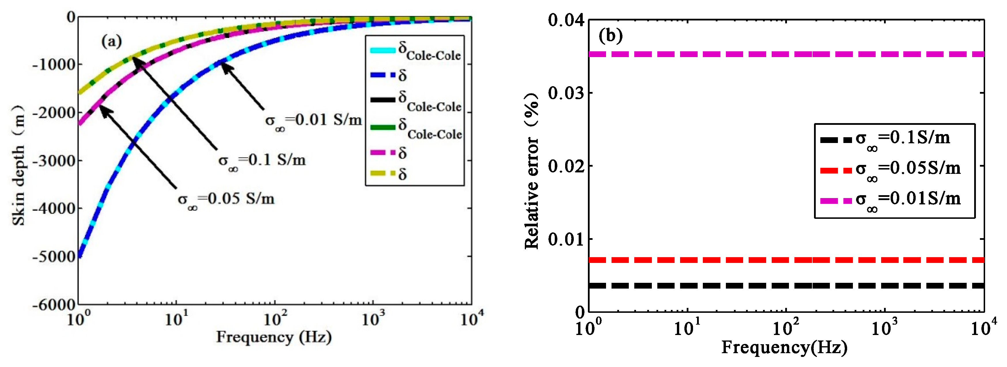
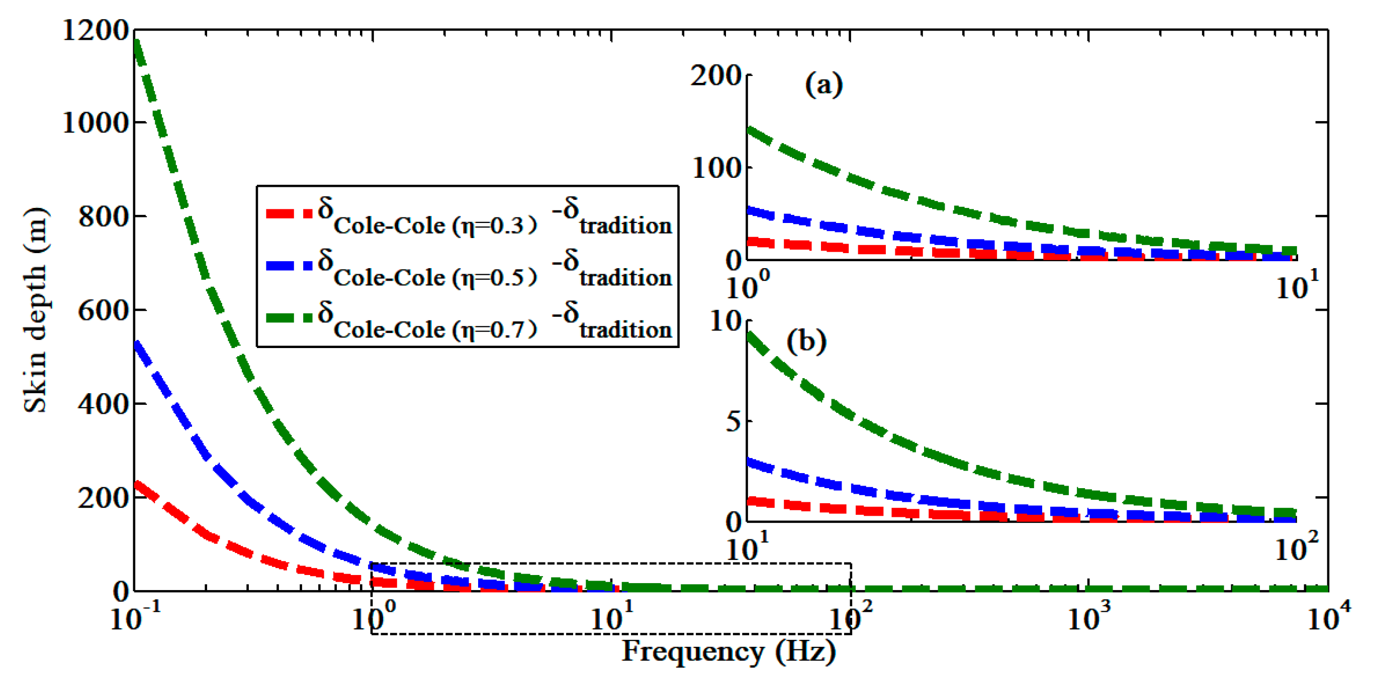
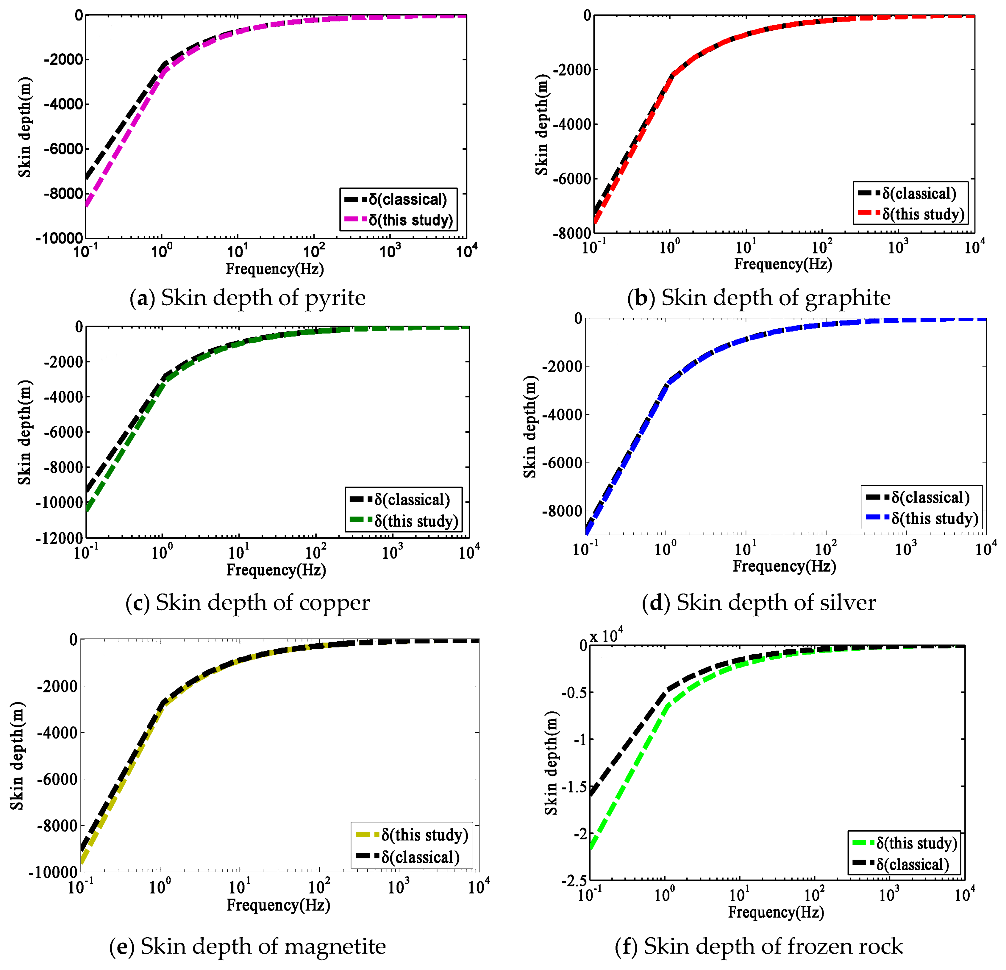
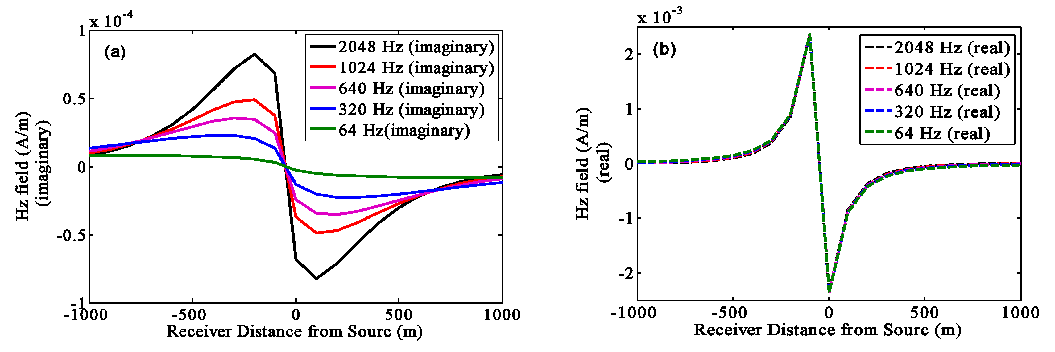
3.1. Verification of the Generalized Skin Depth Formula

Because item ω 2 μ ε is not ignored in this paper, to verify the accuracy of the generalized skin depth calculation method, the chargeability is set to η = 0 and the generalized skin depth is calculated by Equation (15) and compared with the classical skin depth (Equation (8)). The conductivity values are σ = 0.01   S / m , σ = 0.05   S / m , and σ = 0.1   S / m . The frequency sampling range is 10 0 10 4   Hz . The results are shown in Figure 1.
Figure 1a shows a comparison of the generalized skin depth of polarized media with the classical skin depth. Figure 1b shows the relative error. When η is zero, there is no polarization, and the generalized skin depth of polarized medium is consistent with the calculation results of the classical skin depth expression. From Figure 1b, the calculation error is less than 1%, which verifies that the generalized skin depth can be equal to traditional skin depth when chargeability is zero.

3.2. Effect of the Polarization Parameters on the Generalized Skin Depth

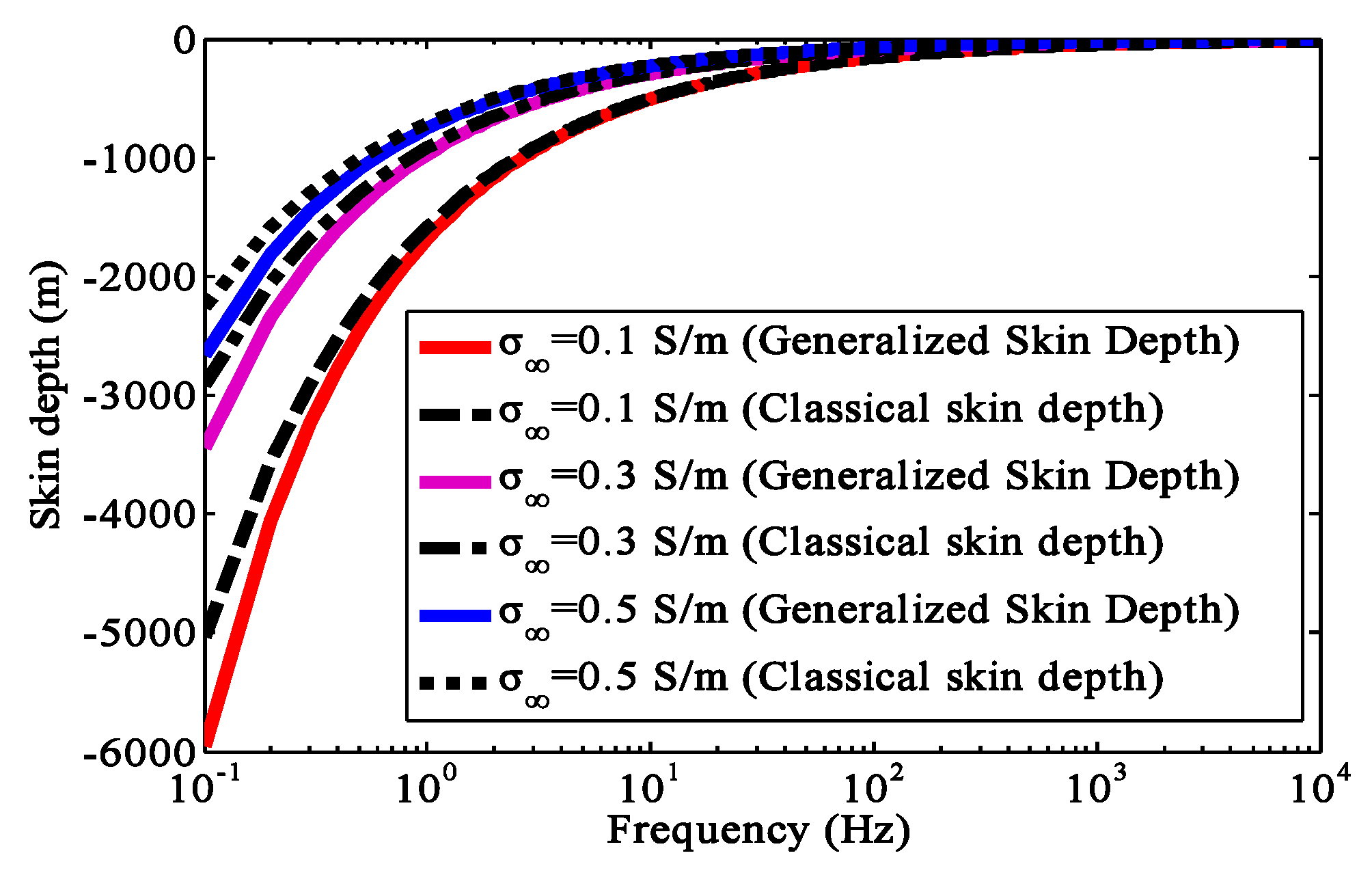
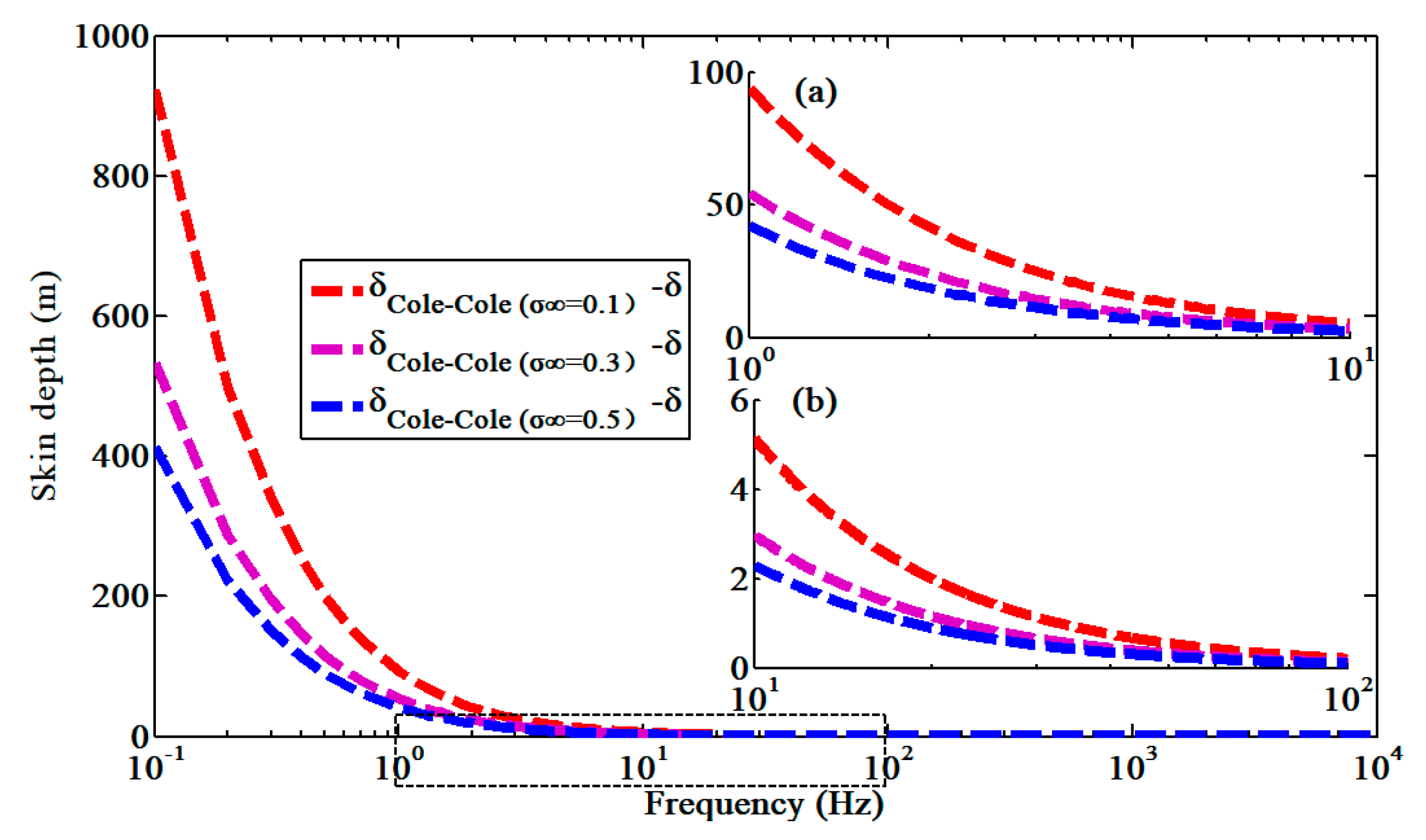
3.2.1. Influence of the Conductivity on the Generalized Skin Depth

Conductivity is an important parameter affecting the generalized skin depth. To analyze the effect of conductivity on the generalized skin depth, we chose the chargeability as η = 0.5 and the conductivities as σ = 0.1   S / m , σ = 0.3   S / m , and σ = 0.5   S / m . The calculation results are shown in Figure 2. From comparison with the classical skin depth formula, the absolute error is shown in Figure 3.
As shown in Figure 2 and Figure 3, the generalized skin depth increased with decreasing conductivity. Compared with the classical skin depth, the generalized skin depth was deeper. The absolute error increased with decreasing conductivity and frequency. The effect of conductivity on the generalized skin depth was mainly concentrated at f < 10   Hz ; when the frequency f > 10   Hz , the absolute error between the generalized skin depth and classical skin depth was less than 5 m. As the frequency continued to increase, the final generalized skin depth and classical skin depth tended to coincide.

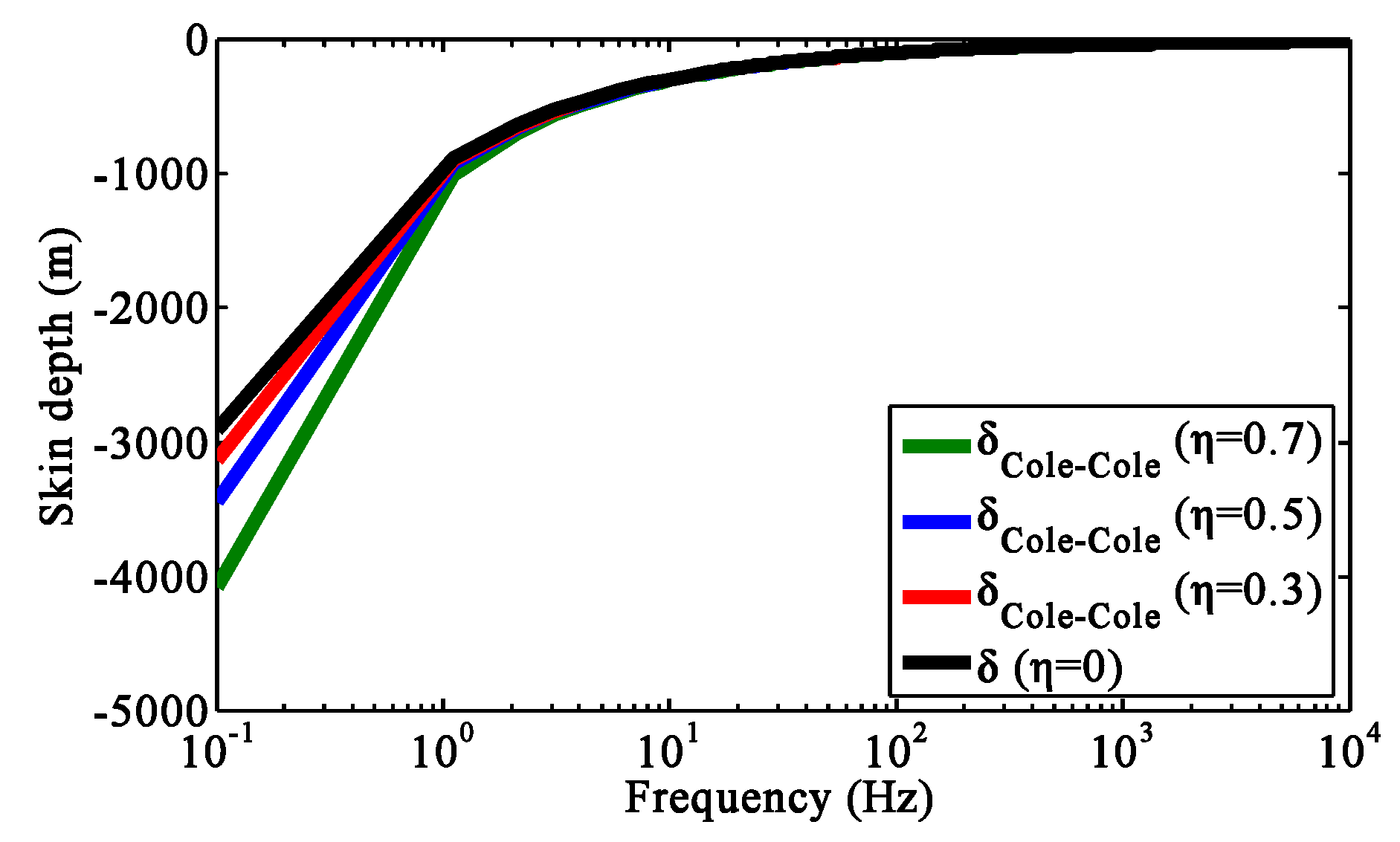
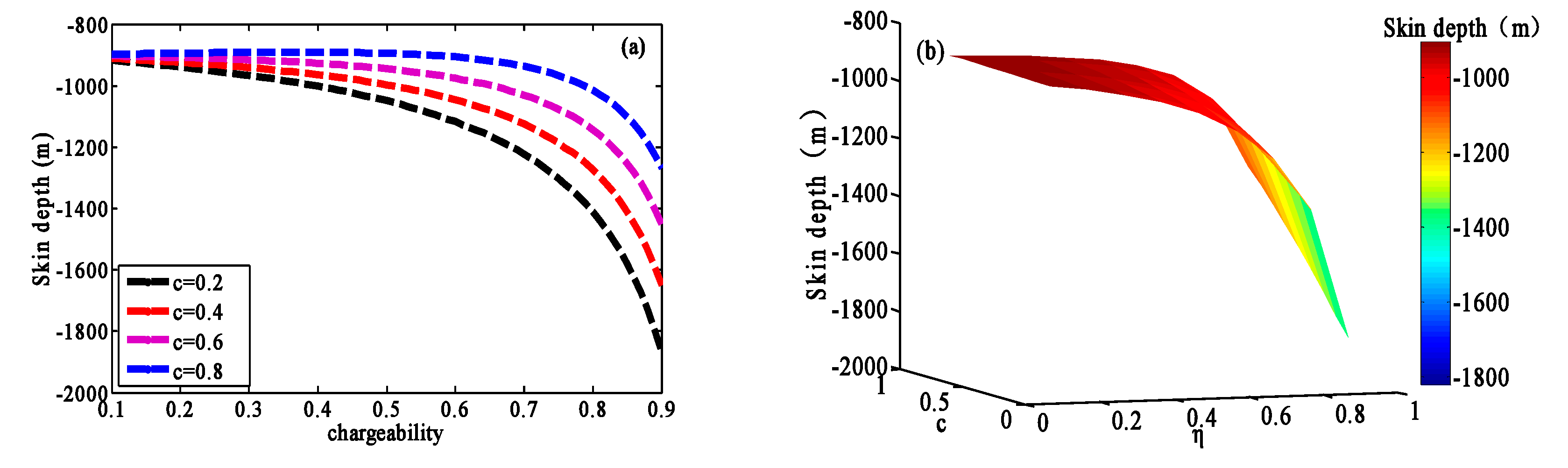
3.2.2. Effect of the Chargeability on the Generalized Skin Depth

The chargeability is one of the most important parameters of a polarized medium based on the Cole–Cole model, which can well reflect the charging and discharging ability of the medium. To calculate the effect of chargeability on the generalized skin depth of polarized media, we chose the frequency range 10 1 10 4   Hz , frequency dependence c = 0.5 , characteristic time constant τ = 1   s , and conductivity at infinite frequency σ = 0.3   S / m . The skin depth varied with frequency and chargeability, as shown in Figure 4. To quantitatively analyze the skin depth of generalized polarized media, we give the absolute error between the generalized skin depth and classical skin depth at different chargeability δ absolute   error = | δ cole-cole δ Classical | in Figure 5.
Figure 4 and Figure 5 show that the generalized skin depth of polarized media and the classical skin depth decreased with increasing frequency. When other parameters remained unchanged, the generalized skin depth and absolute error increased with increasing chargeability. The effect of chargeability on generalized skin depth was mainly concentrated in the low-frequency band, approximately f < 10   Hz . When the frequency f < 10   Hz , the generalized skin depth was deeper than the classical skin depth, which also shows that the effective propagation distance of the EM wave was greater. When the frequency f > 10   Hz , with increasing frequency, the effect of chargeability on the generalized skin depth decreased, and the generalized skin depth under each chargeability was close to the classical skin depth.

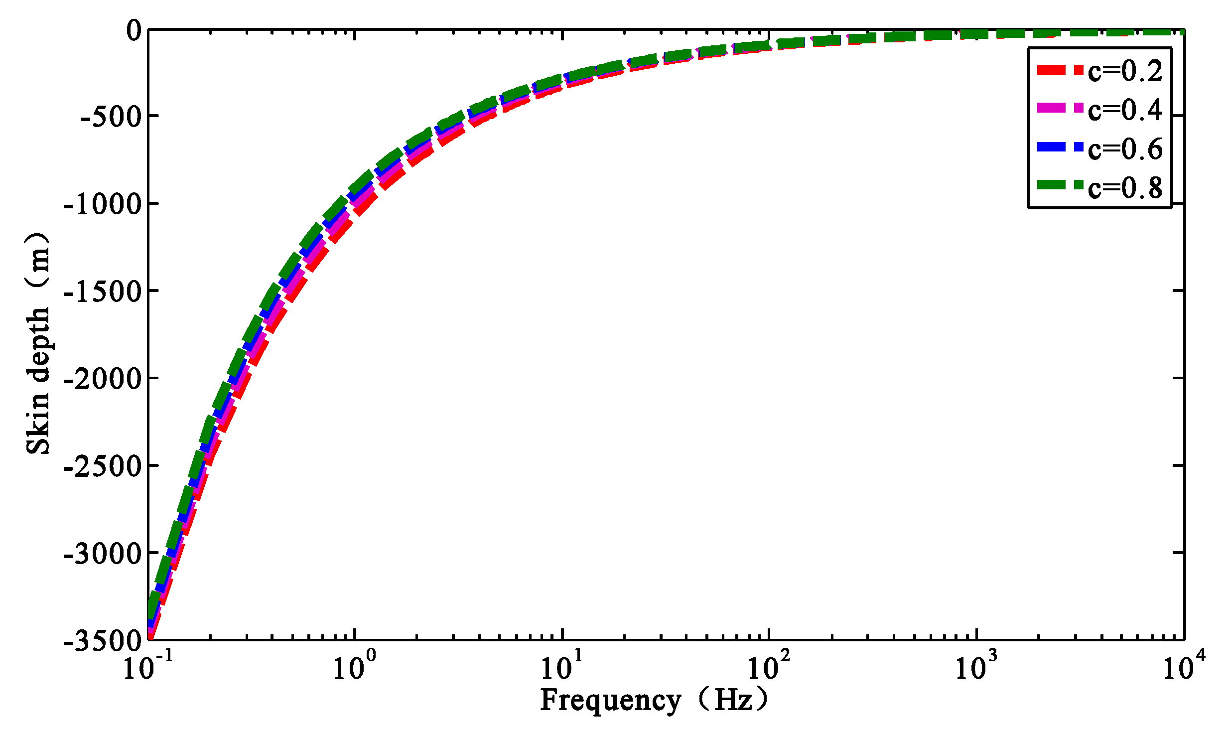
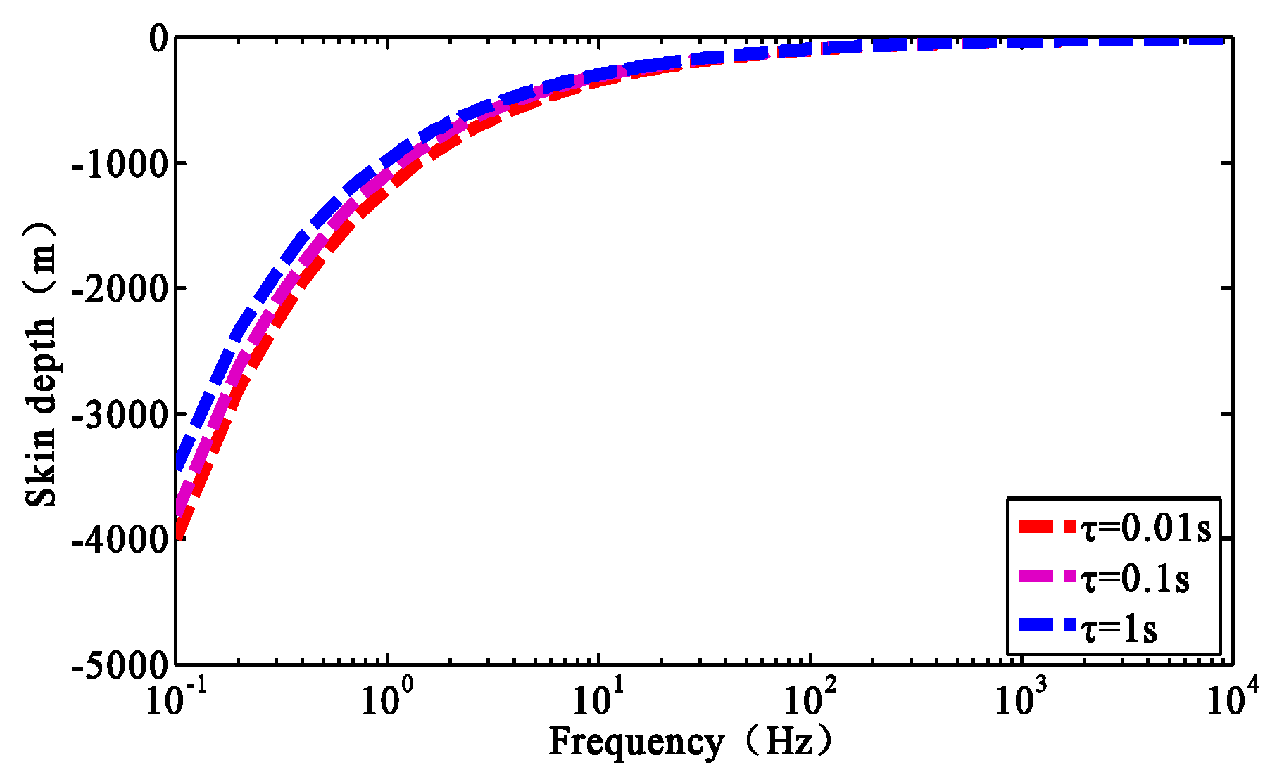
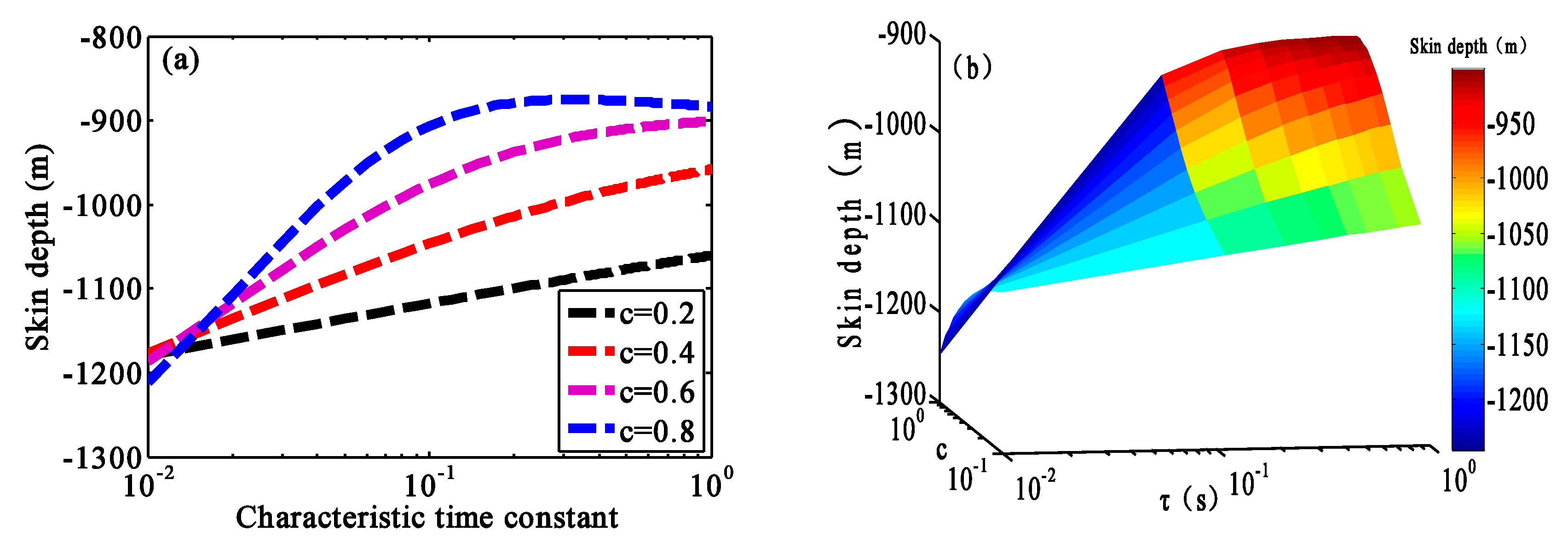
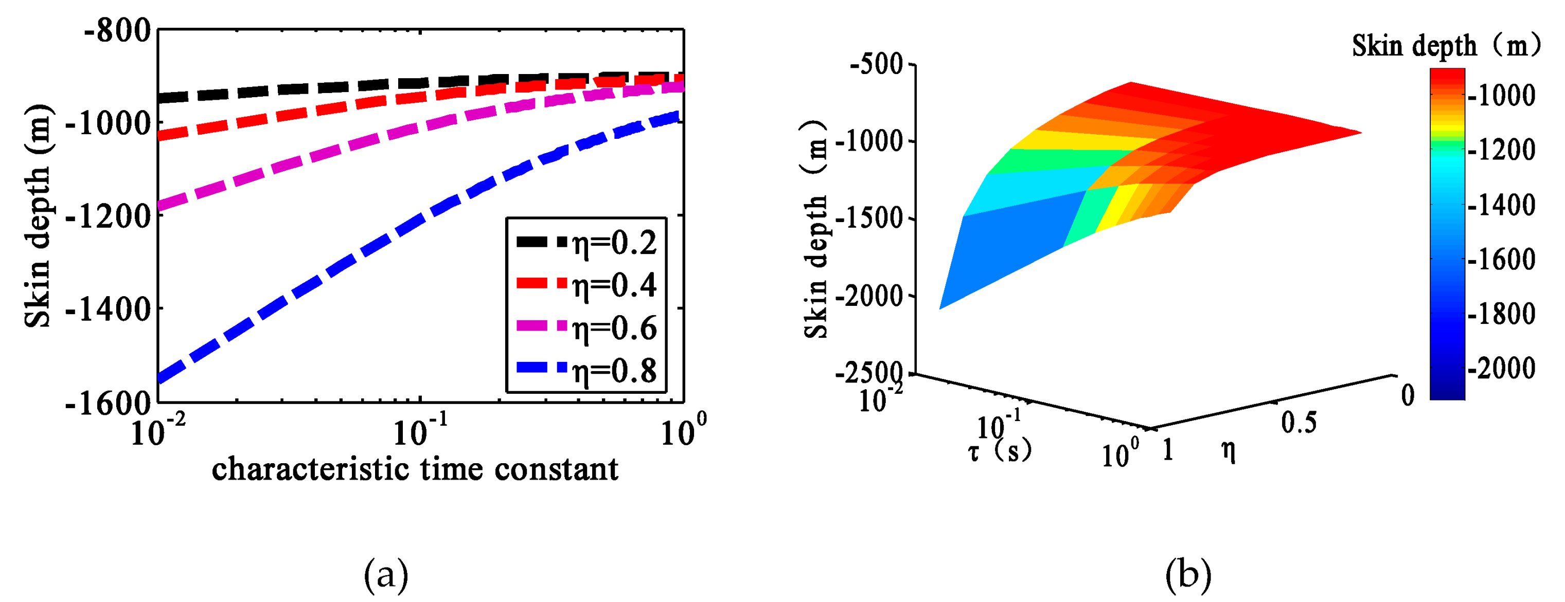
3.2.3. Influence of the Frequency Dependence and Characteristic Time Constant on the Generalized Skin Depth

In addition to the conductivity and chargeability, the generalized skin depth was also affected by the frequency dependence and characteristic time constant. Consider a frequency range of 10 1 10 4   Hz , a characteristic time constant τ = 1   s , a conductivity at infinite frequency σ = 0.3   S / m , chargeability η = 0.5 , and frequency dependence values of c = 0.2 , c = 0.4 , c = 0.6 , and c = 0.8 . The generalized skin depth under different frequency dependence values is shown in Figure 6.
As shown in Figure 6, the generalized skin depth decreased with increasing frequency dependence. The effect of the frequency dependence on the generalized skin depth was concentrated mainly in the low-frequency band at approximately f < 10   Hz . When the frequency f > 10   Hz , with increasing frequency, the effect of the frequency dependence of the generalized skin depth decreased gradually, and the generalized skin depths under different frequency dependence values converged. The frequency range over which the frequency dependence had the most obvious effect on the generalized skin depth was approximately 0.3 Hz–3 Hz.
Keeping the other parameters unchanged, we chose a frequency dependence of c = 0.5 and the characteristic time constants τ = 0.01   s , τ = 0.1   s , and τ = 1   s . The generalized skin depth under different characteristic time constants is shown in Figure 7.
Figure 7 shows that the generalized skin depth tended to decrease with the increasing characteristic time constant, and the effect of the characteristic time constant on the generalized skin depth was most prominent in the low-frequency band (approximately f < 10   Hz ). With increasing frequency, the generalized skin depths under different characteristic time constants tended to converge.

3.3. Characteristic Analysis of the Generalized Skin Depth at Low Frequency

Four polarization parameters affected the generalized skin depth, and all of them were concentrated in the low-frequency band (approximately f < 10   Hz ). According to the existing transmitter frequency in the laboratory, we chose a frequency of 6.25 Hz. The characteristics of the generalized skin depth at low frequencies were analysed, with the conductivity range 10 2 < σ < 10 0 , c = 0.5 , and τ = 0.1   s . The chargeability values were η = 0.2 , η = 0.4 , η = 0.6 , and η = 0.8 . The effect of the conductivity at infinite frequency ( σ ) and the chargeability ( η ) on the skin depth is shown in Figure 8 for a chargeability range of 0.1 < η < 0.9 and frequency dependence values of c = 0.2 , c = 0.4 , c = 0.6 , and c = 0.8 . The effect of the chargeability ( η ) and frequency dependence (c) on the skin depth is shown in Figure 9 for a characteristic time constant range of 10 2   s < τ < 10 0   s and η = 0.6 . Figure 10 shows the effect of the characteristic time constant ( τ ) and frequency dependence (c) on the skin depth for the same characteristic time constant range, c = 0.5 and τ = 0.1   s . Figure 11 shows the effect of the characteristic time constant ( τ ) and chargeability ( η ) on the skin depth.
Figure 8, Figure 9, Figure 10 and Figure 11 show that in the low-frequency band, the conductivity at infinite frequency decreased gradually and the effects of the chargeability on the generalized skin depth became increasingly obvious. When the chargeability and frequency dependence changed simultaneously, the chargeability was proportional to the generalized skin depth, and the frequency dependence was inversely proportional to the generalized skin depth. When the characteristic time constant and the frequency dependence changed simultaneously, the characteristic time constant was inversely proportional to the generalized skin depth, and the decreasing rate was determined by the frequency dependence. At the same conductivity at infinite frequency, the chargeability was proportional to the generalized skin depth. When the chargeability was small, the frequency dependence had little effect on the generalized skin depth. With increasing chargeability, the frequency dependence had a more obvious effect on the generalized skin depth. When the chargeability and characteristic time constant changed simultaneously, the chargeability was proportional to the generalized skin depth, and the characteristic time constant was inversely proportional to the generalized skin depth. The characteristic time constant was relatively small, and the effect of chargeability on the generalized skin depth was prominent.

4. Skin Depth of Porous Media with Metallic Particles

The skin depth of polarized media depends on not only the frequency and conductivity, but also the chargeability and other parameters. Therefore, when calculating the skin depth of porous media, we need to understand the chargeability and other characteristics. Here, the polarization parameters of metal particles can be fitted by the Cole–Cole model. The polarization parameters of graphite, pyrite, silver, copper, and magnetite were obtained from the experiments conducted in Reference [17]. The range of polarization parameters of frozen rock was given in Reference [18]. The specific parameters selected in this paper are shown in Table 1.
δ G r a p h i t e , δ P y r i t e , δ Silver , δ C o p p e r , δ Magnetite , and δ Frozen   rocks were used to represent the skin depth of graphite, pyrite, silver, copper, magnetite and frozen rock, respectively. Here, we took the actual orebody model as an example to calculate the skin depth using the proposed method and the classical skin depth calculation method, as shown in Figure 12a–f.
Compared with the results of the classical skin depth calculation method, when polarization parameters, such as the chargeability, characteristic time constant, and frequency dependence, were taken into account, the predicted skin depth of the polarized media was deeper. Among the samples characterized here, the frozen rock had the largest skin depth and the graphite had the smallest skin depth. The skin depth of a polarized medium is not determined by a specific parameter. That is, the skin depth of an EM wave in a porous polarized medium depends not only on conductivity, but also on polarization parameters, such as chargeability, characteristic time constant, and frequency dependence. The influence of these parameters cannot be ignored. Therefore, for the depth calculation of the porous polarized medium model, accurate results can be obtained by using the generalized skin depth formula. The relative error between the generalized epidermal depth and classical epidermal depth is shown in Figure 13.
δ relative   error = | δ cole-cole δ classical δ classical | × 100 %
In the range of 10 1 10 4   Hz , the maximum relative errors of silver, graphite, copper, pyrite, magnetite, and frozen rock were 1.84%, 5.145%, 11.88%, 16.89%, 5.63%, and 26.51%, respectively. With decreasing frequency, the relative error increased gradually, as did the effect of the polarization parameters on the skin depth. Therefore, in low-frequency EM detection, to obtain accurate depth interpretation imaging, when implementing the porous polarized metal particle model, the generalized skin depth must be used.
As shown in Figure 13, at the same frequency, the relative error of frozen rock was the largest and that of silver was the smallest. We assumed that a relative error of less than 5% was acceptable. For silver, the chargeability was very small, only 0.037. In the frequency range 10 1 10 4   Hz , the classical skin depth and generalized skin depth were used in the calculation, and the error was acceptable in practical applications. For the graphite model and magnetite model, when the EM detection frequency f < 0.1   Hz , the error between the classical skin depth and generalized skin depth was more than 5%. For the pyrite and copper models, when the frequency was f < 8.1   Hz and f < 33.1   Hz , respectively, the error between the classical skin depth and generalized skin depth was more than 5%. For frozen rock, only if the frequency was f > 4864   Hz , the effect of the polarization parameters on the generalized skin depth could be ignored. For different polarization models, the calculation errors were different at low frequencies. Therefore, the generalized skin depth of polarized media can be used to calculate relatively accurate depth results.

5. Skin Depth Imaging of Polarized Porous Media

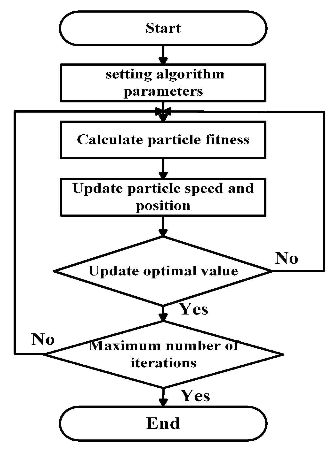
5.1. Polarization Parameter Extraction Based on Particle Swarm Optimization

To verify the validity and applicability of this method, we used two skin depth formulas to explain the depth of polarized media. While imaging the skin depth of polarized media, it is necessary to extract the polarization parameters from the theoretical data. We chose particle swarm optimization (PSO) to extract polarization parameters. PSO is an intelligent optimization algorithm [19,20]. In PSO, each particle corresponds to a fitness value, which is determined by the objective function. All particles update their speed and position by finding individual optimal value and global optimal value. Each search compares the optimal solution with the historical record. If the historical optimal value is exceeded, then the historical optimal position and optimal solution are updated [21,22,23]. Dong L (2018) proposed a new particle swarm optimization algorithm (co-pso) to extract nonlinear IP information from MT (magnetotelluric) sounding data [24].
The calculation formula of induced polarization response is a quaternion function that includes polarization parameters, and its functional relationship is as follows:
B t = f t ( x i )   ( i = 1 , 2 , 3 , 4 )
where B t is theoretical induced polarization response and x i ( i = 1 , 2 , 3 , 4 ) represents four polarization parameters.
The fitness function based on particle swarm optimization is as follows:
Y ( x ) = 1 n i = 1 n | B m ( i ) B t ( i ) |
where B m is the actual measured induced polarization response and Δ B is used to represent the difference between B t and B m . When Δ B approaches 0, it can be considered that B t and B m are equal. Therefore, we can transform the problem of parameter extraction into the problem of minimum value optimization for Equation (18). When extracting all polarization parameters, the fitness function is constructed as follows:
Y m i n ( σ , η , τ , c ) = 1 n i = 1 n | B m ( i ) f t ( x 1 , x 2 , x 3 , x 4 ) |
The specific process of extracting polarization parameters based on the particle swarm optimization algorithm is shown in Figure 14.

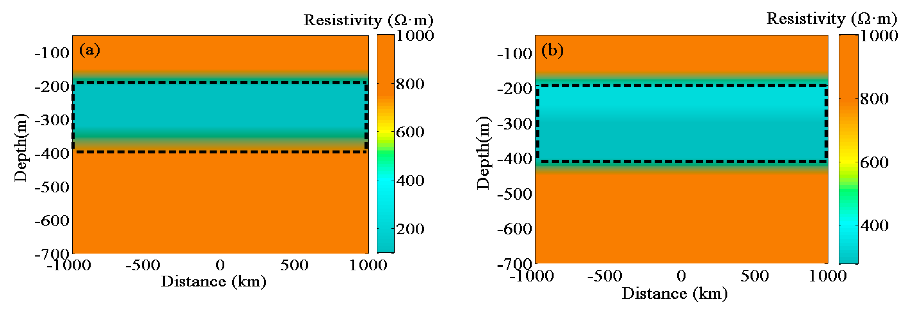
5.2. Skin Depth Imaging of Layered Model for Polarized Medium

To explain the application of generalized polarized media skin depth in field exploration, a layered model with frozen rock was set up, as shown in Figure 15. The conductivity of uniform half space was σ ground = 0.001   S / m , and frozen rock was buried h = 200 m underground. The polarization parameters of frozen rock were given by Reference [18], and to reflect the difference, we chose a larger polarizability: σ = 0.01   S / m , c = 0.46 , η = 0.8 , and τ = 0.00005   s . The thickness of the frozen rock was 200 m. In the electromagnetic theory of Geophysics, the finite difference method is widely used to solve the electromagnetic field [25,26]. The finite difference in the frequency domain (Newman GA, 1995) is used to calculate the layered model [27]. The results are shown in Figure 16.
Taking the electromagnetic response of layered model as an example, the polarization parameters in the response were extracted via particle swarm optimization. The polarization parameters are shown in Table 2. The extracted parameters were consistent with the actual model parameters. The traditional skin depth formula and generalized skin depth for polarized porous media formula were used to image the model depth, as shown in Figure 17a,b.
As shown in Figure 17a,b, the black dotted line indicates the location of the frozen rock set by the theoretical model (Figure 15). Because there were no IP effects for the uniform half space, the upper edge of the frozen rock was the same depth, i.e., approximately 200 m underground, which was consistent with the depth of the theoretical model. When the electromagnetic wave propagated in the polarized medium, the generalized polarized media skin depth formula ( δ cole-cole ) was used to image the lower edge of the frozen rock, and the lower edge of the frozen rock was approximately 402 m underground. Compared with the theoretical model, the relative error was 0.5%. The traditional skin depth formula ( δ ) was used to image the lower edge of the frozen rock. The lower edge of the frozen rock was approximately 325 m underground, with a relative error of 18.75%, compared with the theoretical model. Therefore, using the generalized polarized media skin depth formula to explain the depth of polarized medium had better accuracy.

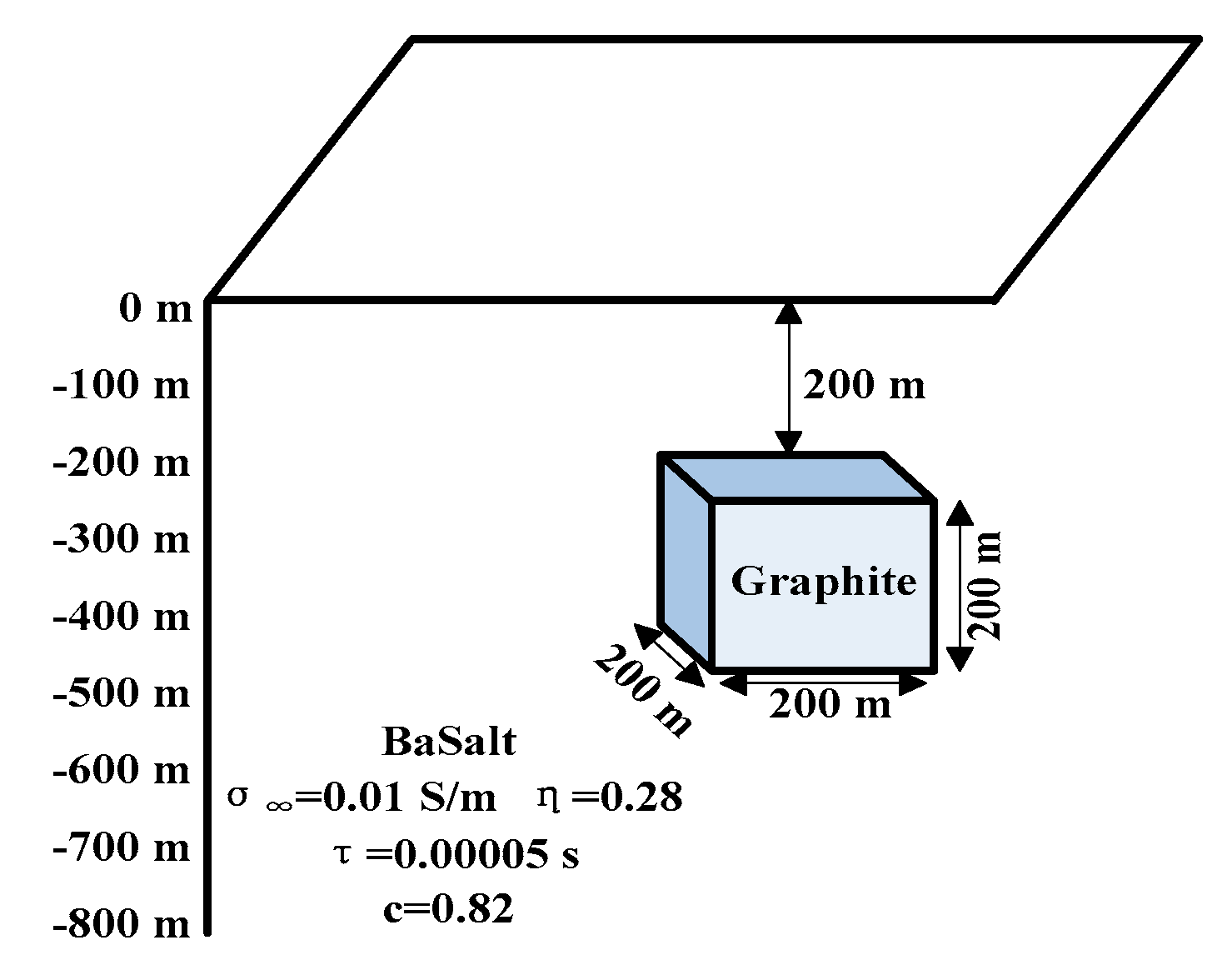
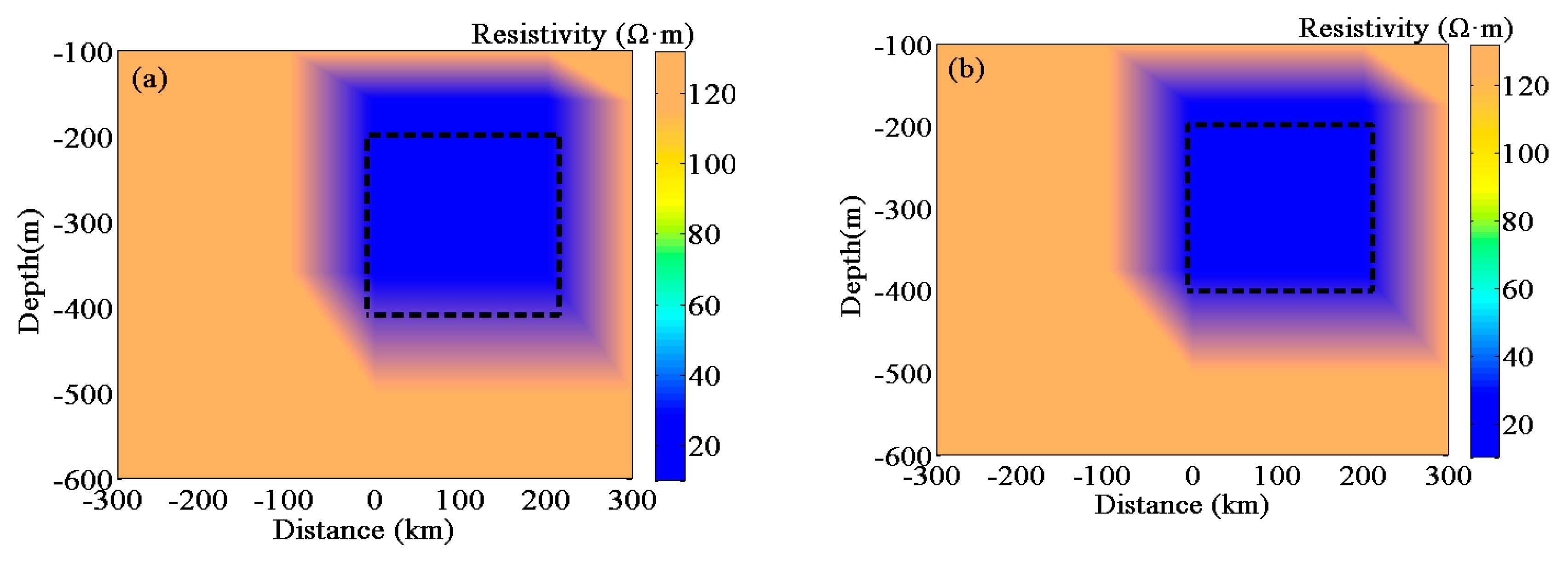
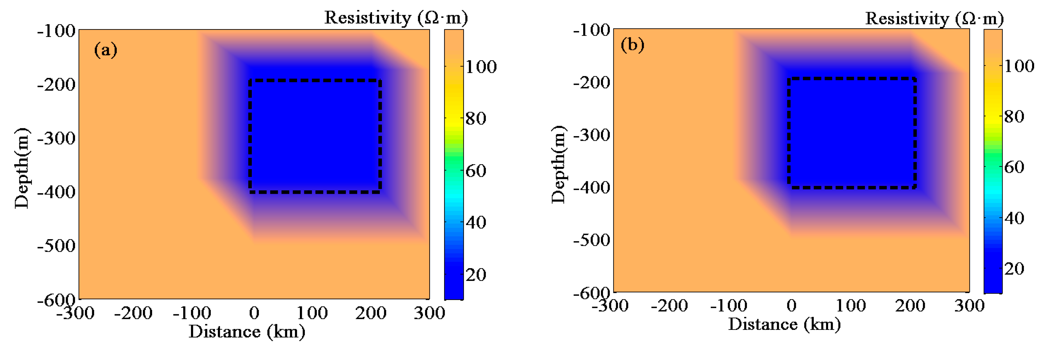
5.3. Depth Interpretation of a Three-Dimensional Chargeable Body

We took basalt as an example, and a three-dimensional chargeable body model was set up, as shown in Figure 18. A graphite ore of dimensions 200 × 200 × 200 m was buried inside the basalt. The burial depth was h = 200 m below the ground. The polarization parameters of basalt were given by Reference [23] as follows: σ = 0.01   S / m , c = 0.82 , η = 0.28 , and τ = 0.00005   s . The polarization parameters of graphite ore were given by Reference [22] as follows: σ = 0.01   S / m , c = 0.82 , η = 0.28 , and τ = 0.00005   s . To show that the skin depth for polarized porous media is universal, we added 50 Hz power frequency noise to the response and extracted the polarization parameters in the case of power frequency noise, as shown in Table 3. The traditional skin depth formula and generalized skin depth formula were used to image the graphite ore, as shown in Figure 19.
As shown in Figure 19, the black dotted line represents the location of the graphite ore in the theoretical model (Figure 18). Due to the noise introduced in the response, the depths of the upper edge and the lower edge of the graphite ore body had large errors. The generalized skin depth formula was used to image the depth of the graphite ore. The depth of the upper edge of the graphite ore body was 175 m, and the depth of the lower edge was approximately 373 m. Compared with the theoretical model, the relative error of the depth of the upper edge was 12.5%, and that of the lower edge was 6.75%. The traditional skin depth formula was also used to image the depth of the graphite ore. The depth of the upper edge of the graphite ore body was 159 m, and the depth of the lower edge was 360 m. Compared with the theoretical model, the relative error of the upper edge was 20.5%, and the relative error of the lower edge was 10%. It can be seen that, with added noise, compared with the traditional skin depth formula, the generalized polarization media skin depth formula had a higher accuracy in the interpretation of the graphite ore depth.
In the actual measurement, due to the interference of noise, it is often necessary to filter the measurement data. We used the Butterworth filter to remove noise, and image interpretation of the filtered results is shown in Figure 20.
As shown in Figure 20, the depth of the graphite ore was imaged by the generalized skin depth formula. The depth of the upper edge of the graphite ore body was 185 m, and the depth of the lower edge was approximately 385 m. Compared with the theoretical model, the relative error of the upper edge depth was 7.5%, and that of the lower edge depth was 3.75%. The traditional skin depth formula was used to image the depth of the graphite ore. The depth of the upper edge of the graphite ore body was 175 m, and the depth of the lower edge was 376 m. Compared with the theoretical model, the relative error of the upper edge was 12.5%, and the relative error of the lower edge was 6%. It can be seen that the electromagnetic wave had a deeper propagation depth in the polarized medium, and the traditional skin depth could not explain the location of graphite ore. Under IP effects, using the generalized skin depth formula to determine the depth of graphite ore was more accurate.

6. Conclusions

In this paper, the classical skin depth formula and the generalized skin depth formula were used to characterize typical orebody models. Under the different models, the relative errors were different. Because silver has low chargeability, the influence of the polarization parameters can be ignored. When calculating the skin depth of graphite and magnetite, the influence of the polarization parameters should be taken into account when the EM detection frequency is f < 0.1   Hz . When calculating the skin depth of pyrite or copper, when the frequency is f < 8.1   Hz and f < 33.1   Hz , better calculation results can be obtained by using generalized skin depth. When calculating the skin depth of frozen rock, the generalized skin depth formula is more applicable. In geophysical exploration, the skin depth of a chargeable body can provide an initial model for data inversion and a fast method for estimating the depth of a polarized medium. Compared with the traditional skin depth formula, the generalized skin depth for polarized porous media has a higher interpretation accuracy.
In the low-frequency band, the EM wave has a relatively deep propagation depth in the polarized medium, so it is better to use the generalized skin depth formula to calculate the accurate depth and to interpret imaging. In the high-frequency band, the polarization parameters can be neglected, so either the generalized skin depth or classical skin depth are suitable for depth calculations. The generalized skin depth formula is more universal. We established a forward model, mainly considering the propagation depth of electromagnetic wave in the polarized mineral resources, and analyzed the skin depth of the regular shape mineral resources. The generalized skin depth model lays a good foundation for the subsequent polarization medium inversion calculation and data interpretation.

Author Contributions

Funding acquisition, Y.J.; investigation, X.M.; project administration, Y.W., J.S. and Q.W.; supervision, Q.W.; writing—original draft, X.M. All authors have read and agreed to the published version of the manuscript.

Funding

This work was supported by the National Natural Science Foundation of China (Grant Number 41674109).

Acknowledgments

We thank the editors and reviewers for comment. Thank you for National “Natural Science Foundation of China (Grant Number 41674109)” support.

Conflicts of Interest

The author declares no conflict of interest.

References

  1. Singh, N.P.; Mogi, T. Effective skin depth of EM fields due to large circular loop and electric dipole sources. Earth Planets Space 2003, 55, 301–313. [Google Scholar] [CrossRef] [Green Version]
  2. Parker, R.L. The existence of a region inaccessible to magnetotelluric sounding. Geophys. J. Int. 1982, 68, 165–170. [Google Scholar] [CrossRef]
  3. Weiping, W. Electromagnetic Response Character of Helicopter Frequency Domain EM System above Uniform Half Space and Its Prospecting Depth. Acta Geosci. Sin. 2003, 24, 285–288. [Google Scholar]
  4. Reid, J.E.; Macnae, J.C. Doubling the effective skin depth with a local source. Geophysics 1990, 64, 732–738. [Google Scholar] [CrossRef]
  5. Singh, N.P.; Mogi, T. Effective Skin Depth with a Local Source and Its Application to Survey Design and Data Interpretation. Seg Tech. Program Expand. Abstr. 2002, 21, 684. [Google Scholar]
  6. Beamish, D. Airborne EM skin depths. Geophys. Prospect. 2004, 52, 439–449. [Google Scholar] [CrossRef] [Green Version]
  7. Chen, W.-Y.; Xue, G.-Q. Effective skin depth of whole EM field due to a grounded wire source. Chin. J. Geophys. 2014, 57, 2314–2320. [Google Scholar]
  8. Xue, G.; Zhou, N.; Chen, W. Research on the Application of a 3-m Transmitter Loop for TEM Surveys in Mountainous Areas. J. Environ. Eng. Geophys. 2014, 19, 3–12. [Google Scholar] [CrossRef]
  9. Xue, J.; Chen, W.; Wang, H. Analysis and application of the detection depth of electrical source Short-offset TEM. Geophys. Geochem. Explor. 2017, 57, 631. [Google Scholar]
  10. Debye, P.; Falkenhagen, H. Dispersion of the conductivity and dielectric constants of strong electrolytes. Phys. Z. 1928, 29, 401–426. [Google Scholar]
  11. Cole, K.S.; Cole, R.H. Dispersion and absorption in dielectrics. I. Alternating current characteristics. J. Chem. Phys. 1941, 9, 341–351. [Google Scholar] [CrossRef] [Green Version]
  12. Ghorbani, A.; Cosenza, P.; Revil, A.; Zamora, M.; Schmutz, M.; Florsch, N.; Jougnot, D. Non-invasive monitoring of water content and textural changes in clay-rocks using spectral induced polarization: A laboratory investigation. Appl. Clay Sci. 2009, 43, 493–502. [Google Scholar] [CrossRef]
  13. Duvillard, P.A.; Revil, A.; Qi, Y.; SoueidAhmed, A.; Coperey, A.; Ravanel, L. Three-dimensional electrical conductivity and induced polarization tomography of a rock glacier. J. Geophys. Res. 2018, 123, 9528–9554. [Google Scholar] [CrossRef]
  14. Pelton, W.H.; Ward, S.H.; Hallof, P.G.; Sill, W.R.; Nelson, P.H. Mineral discrimination and removal of inductive coupling with multi-frequency IP. Geophysics 1978, 43, 588–609. [Google Scholar] [CrossRef]
  15. Stratton, J.A. Electromagnetic Theory; McGraw-Hill Book CO.: New York, NY, USA, 1941. [Google Scholar]
  16. Spies, B.R. Depth of investigation in electromagnetic sounding methods. Geophysics 1989, 54, 872. [Google Scholar] [CrossRef]
  17. Revil, A.; Mao, D.; Shao, Z. Induced polarization response of porous media with metallic particles—Part 6: The case of metals and semimetals. Geophysics 2016, 82, 97–110. [Google Scholar] [CrossRef]
  18. Kozhevnikov, N.O.; Antonov, E.Y. Fast-decaying inductively induced polarization in frozen ground: A synthesis of results and models. J. Appl. Geophys. 2012, 82, 171–183. [Google Scholar] [CrossRef]
  19. Kennedy, J.; Eberhart, R. Particle swarm optimization. In Proceedings of the ICNN′95—International Conference on Neural Networks, Perth, Australia, 27 November–1 December 1995. [Google Scholar]
  20. Shi, Y.H.; Eberhart, R.C. A Modified Particle Swarm Optimizer. In Proceedings of the 1998 IEEE International Conference on Evolutionary Computation Proceedings. IEEE World Congress on Computational Intelligence, Alaska, AK, USA, 4–9 May 1998. [Google Scholar]
  21. Singh, R.P.; Mukherjee, V.; Ghoshal, S.P. Particle swarm optimization with an aging leader and challengers algorithm for the solution of optimal power flow problem. Appl. Soft Comput. 2016, 40, 161–177. [Google Scholar] [CrossRef]
  22. Ketabi, A.; Fini, M.H. Adaptive underfrequency load shedding using particle swarm optimization algorithm. J. Appl. Res. Technol. 2017, 15, 54–60. [Google Scholar] [CrossRef]
  23. Agarwal, M.; Srivastava, G.M.S. Genetic Algorithm Enabled Particle Swarm Optimization (PSOGA) based Task Scheduling in Cloud Computing Environment. Int. J. Inf. Technol. Decis. Mak. 2018, 17, 1237–1267. [Google Scholar] [CrossRef]
  24. Dong, L.; Li, D.Q.; Jiang, F.B. A two-stage CO-PSO minimum structure inversion using CUDA for extracting IP information from MT data. J. Cent. South Univ. 2018, 25, 1195–1212. [Google Scholar] [CrossRef]
  25. Foundations of Geophysical Electromagnetic Theory and Methods Electromagnetic Migration. Available online: https://www.onacademic.com/detail/journal_1000040120116010_f94e.html (accessed on 19 February 2020).
  26. Zhdanov, M.S. Electromagnetic methods in the frequency and time domains. Methods Geochem. Geophys. 2009, 43, 649–693. [Google Scholar]
  27. Newman, G.A. Frequency-domain modeling of airborne electromagnetic responses using staggered finite differences. Geophys. Prosp. 1995, 43, 1021–1042. [Google Scholar] [CrossRef]
Figure 1. The η = 0 generalized skin depth of polarized media ((a) calculation of depth, (b) relative error).
Applsci 10 01456 g001
Figure 2. Generalized skin depth of polarized media at different conductivities (red, purple, and blue represent the σ = 0.1   S / m , σ = 0.3   S / m , and σ = 0.5   S / m generalized skin depths of the polarized media, respectively, and the black curve represents the classical skin depth).
Applsci 10 01456 g002
Figure 3. The absolute errors of the generalized skin depth and classical skin depth under different conductivities ((a) and (b) represent the magnified maps of different frequency bands and red, purple, and blue represent the absolute error between the two when the conductivity is 0.1 S/m, 0.3 S/m, and 0.5 S/m, respectively).
Applsci 10 01456 g003
Figure 4. Skin depth of generalized polarized media at different chargeability values (black curve represents the traditional skin depth without polarization and red, blue, and green represent the generalized skin depth of polarized media with a chargeability of η = 0.3 , η = 0.5 , and η = 0.7 , respectively).
Applsci 10 01456 g004
Figure 5. Absolute error between the generalized skin depth of polarized media and classical skin depth under different chargeability values ((a) and (b) represent magnified maps of different frequencies; red, blue, and green represent the absolute errors when the chargeability is 0.3, 0.5, and 0.7, respectively).
Applsci 10 01456 g005
Figure 6. Generalized skin depth under different frequency dependence values.
Applsci 10 01456 g006
Figure 7. Generalized skin depth curves with different characteristic time constants.
Applsci 10 01456 g007
Figure 8. The effect of the conductivity at infinite frequency and the chargeability on the skin depth ((a) 2D curve, (b) 3D view).
Applsci 10 01456 g008
Figure 9. The effect of the chargeability and the frequency dependence on the skin depth ((a) 2D curve, (b) 3D view)
Applsci 10 01456 g009
Figure 10. The effect of the characteristic time constant and the frequency dependence on the skin depth ((a) 2D curve, (b) 3D view).
Applsci 10 01456 g010
Figure 11. The effect of the characteristic time constant and the chargeability on the skin depth ((a) 2D curve, (b) 3D view).
Applsci 10 01456 g011
Figure 12. Six models were used to calculate the skin depth (among them, the black curve is the result of the classical skin depth formula and the curve in colour is the result of the generalized skin depth formula).
Applsci 10 01456 g012
Figure 13. Relative error curves.
Applsci 10 01456 g013
Figure 14. Flow chart of polarization parameter extraction based on particle swarm optimization.
Applsci 10 01456 g014
Figure 15. Layered polarization model of frozen rock.
Applsci 10 01456 g015
Figure 16. The magnetic field response of the imaginary and real components at different frequencies ((a) imaginary part; (b) real part).
Applsci 10 01456 g016
Figure 17. Porous polarized media depth imaging ((a) traditional skin depth formula; (b) generalized polarized media skin depth formula).
Applsci 10 01456 g017
Figure 18. 3D polarization model.
Applsci 10 01456 g018
Figure 19. Depth imaging of the 3D polarization model with 50 Hz power frequency noise ((a) traditional skin depth formula; (b) generalized skin depth for polarized porous media).
Applsci 10 01456 g019
Figure 20. Depth imaging of the 3D polarization model after denoising ((a) traditional skin depth formula; (b) generalized skin depth for polarized porous media).
Applsci 10 01456 g020
Table 1. Polarization parameters of common metal particles.
Metallic ParticlesChargeability ηConductivity at Infinite Frequency σ (S/m)Frequency Dependence cCharacteristic Time Constant τ(s)
Graphite0.3080.04790.62
Pyrite0.2750.04720.780.0155
Silver0.0370.03250.620.004
Copper0.2210.02890.410.0042
Magnetite0.130.03070.380.01
Frozen rocks0.460.010.80.00005
Table 2. Extraction results of polarization parameters with layered model. Induced polarization (IP).
IP ParametersTheoretical ModelExtraction Parameter
σ (S/m)0.010.0096
c 0.460.4612
η 0.80.8001
τ (s)0.00000.000056
Table 3. Extraction results of the polarization parameters of the 3D polarization model with noise.
IP ParametersTheoretical ModelExtraction Parameter
BasaltGraphiteBasaltGraphite
σ (S/m)0.010.04790.01350.0491
c 0.820.60.81550.57
η 0.280.3080.24980.334
τ (s)0.0000520.000051.93

