3.1. Effect of Graphene Content on the Property of Graphene/PLA Composite Absorbers
The reflection loss of graphene/PLA composite absorbers with different graphene content is presented in
Figure 1. It can be seen that, in the frequency range 10.0–15.8 GHz, the reflection loss of 7 wt% graphene/PLA composite absorber is lower than −4 dB and the minimum reflection loss value is −8.3 dB at the frequency of 13.2 GHz; in the frequency range 10.2–15.2 GHz, 9 wt% graphene/PLA composite absorber has a reflection loss of less than −4 dB and a minimum reflection loss of −7.3 dB at the frequency of 12.2 GHz. The reflection loss of 5 wt% graphene/PLA composite absorber is higher than −4 dB in the whole frequency band tested, reaching the minimum reflection loss value of −3.1 dB at the frequency of 14.2 GHz.
As shown in
Figure 2, the real and imaginary parts of the complex permittivity of graphene/PLA composite absorber decrease with an increase of frequency. In
Figure 2a, as the mass fraction of graphene increases, the real part of the complex permittivity of the composite absorber increases. When the graphene content is 9 wt%, the real part of the complex permittivity is the highest, and at 5 wt% it is the lowest, because as the mass fraction of graphene increases, the number of electric dipoles stored in the composite absorber increases, and the polarization of the electric dipole increases, resulting in an increase in the real part of the complex permittivity [
9,
10]. As shown in
Figure 2b, when the graphene content is 7 wt%, the composite absorber has the highest complex permittivity imaginary part, followed by 9 wt% and the lowest which is 5 wt%. According to the theory of free electrons [
11],
, where
is the electrical conductivity of the material,
ω is the pi, and
is the complex permittivity of free space. It can be concluded that the imaginary part of the complex permittivity is positively correlated with the conductivity. The electrical conductivity of the composite is 2.06 × 10
−4 S/cm when the content of graphene is 5 wt%. When the amount of graphene added is 7 wt%, the electrical conductivity is significantly increased to 2.71 × 10
−3 S/cm, indicating that the density of the three-dimensional conductive network is increased when the graphene content is increased from 5 wt% to 7 wt%. When the graphene content is 9 wt%, the electrical conductivity of the composite is 2.59 × 10
−3 S/cm. Due to the enhanced adsorption between graphene, the dispersion state of graphene in the matrix is affected and the conductive network structure is destroyed, and thus the conductivity is dropped.
The SEM sectional view of PLA absorber and graphene/PLA composite absorbers are shown in
Figure 3. It can be seen from
Figure 3a that the pure PLA absorber has a relatively flat section. It can be seen from
Figure 3b that the graphene is coated on the surface of the PLA matrix. Due to the stacking phenomenon between the graphene sheets, the wrinkles are more obvious when the amount of graphene is 7 wt% (as shown in
Figure 3c). When the amount of graphene added is 9 wt%, as shown in
Figure 3d, the graphene powders are agglomerated together and the absorbing property of the composite is weakened due to the presence of electron scattering. It can be seen that in the 8.2 to 18.0 GHz band, when the thickness of the composite part is constant, the absorbing property of the 7 wt% graphene/PLA composite is relatively better.
3.2. Effect of Nano-Fe3O4 Content on the Property of Nano-Fe3O4/PLA Composite Absorbers
Comparisons of the reflection loss of the composite absorbers are shown as
Figure 1 and
Figure 4, respectively. The variation is similar to that of graphene/PLA composite absorbers. The difference is that the minimum reflection loss value is shifted to the high frequency band. In the band of 8.2 to 18.0 GHz, when the content of nano-Fe
3O
4 in the nano-Fe
3O
4/PLA composite absorber is 20 wt%, the reflection loss curve is the lowest, followed by 30 wt%, and finally 10 wt%. The minimum reflection loss values achieved −4.8 dB, −3.9 dB, −3.3 dB, respectively.
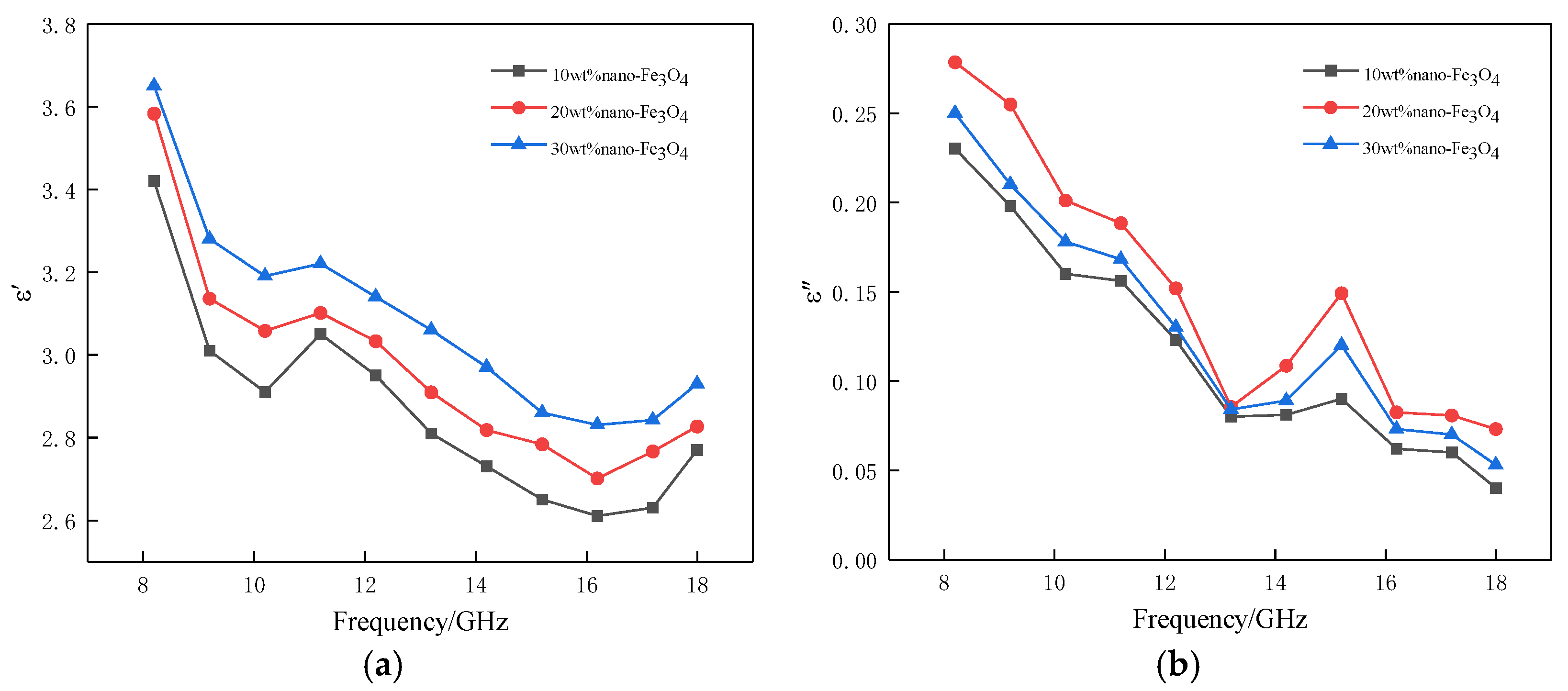
As shown in
Figure 5a,b, the complex permittivity of the nano-Fe
3O
4/PLA composite absorber decreases with increasing frequency. The complex permittivity can be expressed as
, where
and
are the complex dielectric constants of
and
, respectively,
is the relaxation time, and
is the circular frequency [
12,
13,
14,
15]. It can be seen that the complex permittivity ε decreases as the frequency ƒ (relative to the circular frequency ω) increases. In
Figure 5a, with an increase of the mass fraction of nano-Fe
3O
4, the real part of the complex permittivity is improved. When the content of nano-Fe
3O
4 is 30 wt%, the complex permittivity is the highest, it is the second highest when the content is 20 wt%, and it is the lowest when the content is 10 wt%. This is explained by the fact that as the mass fraction of nano-Fe
3O
4 increases, the number of multi-interfaces formed by nano-Fe
3O
4 adsorbed on the surface of PLA and the interface polarization are increased, which leads to the increase in the real part of the complex permittivity. As shown in
Figure 5b, when the content of nano-Fe
3O
4 in the nano-Fe
3O
4/PLA composite absorber is 20 wt%, the complex permittivity imaginary part is the highest, followed by when the content is 30 wt%, and it is the lowest when the content is 10 wt%. The reason for this is that as the amount of nano-Fe
3O
4 increased, the number of dipoles in the composite absorber increased, which caused the dipole polarization effect of the material when the addition amount of nano-Fe
3O
4 reached 30 wt%. Due to the enhanced adsorption between nano-Fe
3O
4, the dispersion state of nano-Fe
3O
4 in the matrix is affected, which weakens the ability of the dipole to lose electromagnetic waves.
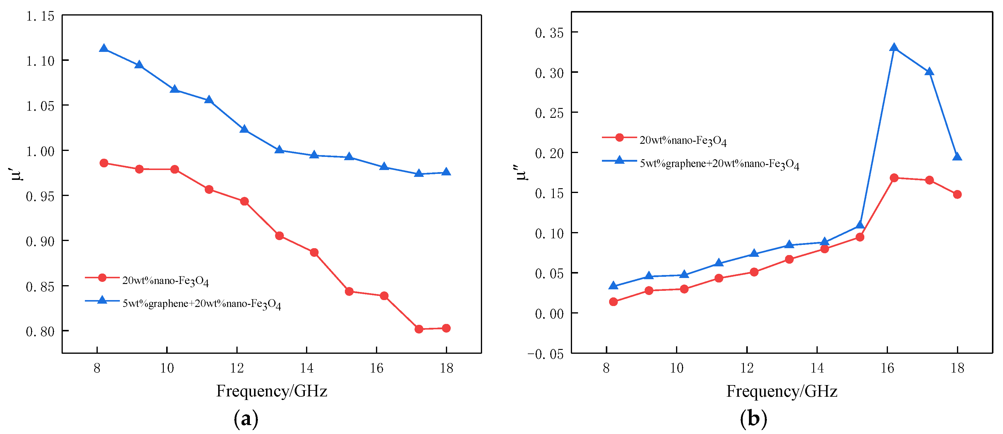
Figure 6 is a graph showing the complex permeability of nano-Fe
3O
4/PLA composite absorbers with different nano-Fe
3O
4 content. It can be seen from
Figure 6a that with an increase of frequency, the real part of the complex permeability gradually decreases, because the speed of the dielectric magnetization in the nano-Fe
3O
4/PLA composite absorber cannot keep up with the speed of the magnetic field change, forming a hysteresis phenomenon [
16]. When the content of nano-Fe
3O
4 in the nano-Fe
3O
4/PLA composite absorber is 30 wt%, the real part of the complex permeability is the highest, followed by when the content is 20 wt%, and the lowest is when the content is 10 wt%. The increase of nano-Fe
3O
4 brings about improvement in magnetic storage. Therefore, the greater the content of nano-Fe
3O
4, the higher the value of the complex permeability real part. It can be seen from
Figure 6b that the imaginary part of the complex permeability increases first, and then decreases; there exists a drastic change at a frequency of 16 GHz, because nano-Fe
3O
4 produces the ferromagnetic resonance phenomenon at higher frequencies. When the content of nano-Fe
3O
4 in nano-Fe
3O
4/PLA composite absorber is 20 wt%, the imaginary part of complex permeability is the highest, followed by when the content is 30 wt%, and the lowest when the content is 10 wt%. When the content of nano-Fe
3O
4 in the nano-Fe
3O
4/PLA composite absorber is 10 wt%, the polarization of Fe
2+ ions in nano-Fe
3O
4 is weak. When the addition amount of nano-Fe
3O
4 is 20 wt%, the polarization of Fe
2+ ions in nano-Fe
3O
4 is enhanced, which causes the improvement of magnetic loss. When the content of nano-Fe
3O
4 is 30 wt%, a large amount of nano-Fe
3O
4 is agglomerated together, the magnetic loss of the electromagnetic wave is weakened, and therefore the imaginary part of the complex permeability has dropped.
One of the earliest ferrites that people have come into contact with is Fe
3O
4. It has high dielectric and magnetic properties, etc., widely used in the field of absorbing waves [
17].
Figure 7 shows a SEM cross-section of pure PLA and nano-Fe
3O
4/PLA composite absorbers. As can be seen from
Figure 7a, the pure PLA section has no holes. When the content of nano-Fe
3O
4 is 10 wt%, as shown in
Figure 7b, the nano-Fe
3O
4 magnetic microspheres begin to adsorb on the surface of PLA, forming “protrusions” with pores. These “protrusions” promote multiple reflection losses of electromagnetic waves inside the material, while holes can act as polarization centers, generating polarization and relaxation under varying electromagnetic fields, thereby consuming electromagnetic energy. When the addition amount of nano-Fe
3O
4 is 20 wt%, as shown in
Figure 7c, more nano-Fe
3O
4 magnetic microspheres are adsorbed on the PLA surface, which promotes the loss and absorption of electromagnetic waves. When the amount of nano-Fe
3O
4 added reaches 30 wt%, as shown in
Figure 7d, the nano-Fe
3O
4 magnetic microspheres are agglomerated and the pores become larger. Agglomeration affects the ability of electromagnetic wave loss, since large holes allow electromagnetic waves to pass through the material directly, which weakens the absorption performance.
3.3. Effect of Absorbing Agent Composition on the Property of Composite Absorbers
The reflection loss of composite absorbers with different absorbing agent composition is presented in
Figure 8. It can be seen that as the frequency increases, the variation of the reflection loss of the three composite absorbers first decreases, and then rises. Among them, the reflection loss of graphene/nano-Fe
3O
4/PLA composite absorber is significantly lower than that of graphene/PLA and nano-Fe
3O
4/PLA composite absorbers, and the effective absorption bandwidth (RL ≤ −10 dB) of the graphene/nano-Fe
3O
4/PLA composite absorber is 3.6 GHz (12.4 to 16.0 GHz).
The complex permittivity of composite absorbers with different absorbing agent composition are presented in
Figure 9. Their variation law is gradually decreasing with increasing frequency, which is due to the relaxation phenomenon of the dielectric polarization in the composite absorber which cannot keep up with the changing speed of the electric field [
18]. It can be seen from
Figure 9a that the real part of the complex permittivity of the graphene/nano-Fe
3O
4/PLA composite absorber is higher than that of the graphene/PLA and nano-Fe
3O
4/PLA composite absorbers, because the real part of the complex permittivity of the material mainly depends on the interfacial polarization between the absorbing agent and the substrate. The graphene/nano-Fe
3O
4/PLA composite absorber increases the graphene/PLA interface and the graphene/nano-Fe
3O
4 interface with respect to the nano-Fe
3O
4/PLA composite absorber; the graphene/nano-Fe
3O
4/PLA composite absorber increases the nano-Fe
3O
4/PLA interface and the graphene/nano-Fe
3O
4 interface relative to graphite/PLA composite absorber. The increase of the interface leads to the highest real part of the complex permittivity. Secondly, since the dielectric property of graphene is significantly better than those of nano-Fe
3O
4, the polarization of graphene/PLA interface is stronger than that of nano-Fe
3O
4/PLA interface. Therefore, the real part of the complex permittivity of graphene/PLA composite absorber is higher than that of nano-Fe
3O
4/PLA composite absorber. It can be seen from
Figure 9b that the imaginary part of the complex permittivity of graphene/nano-Fe
3O
4/PLA composite absorber is higher than graphene/PLA and nano-Fe
3O
4/PLA composite absorbers, because in the microwave frequency band, the inherent electric dipole orientation polarization and interfacial polarization have the characteristics of large damping and small restoring force, which becomes the main factor affecting “
ε″. In addition, since graphene itself is superior in conductivity to nano-Fe
3O
4, the imaginary part of complex permittivity of graphene/PLA composite absorber is higher than that of nano-Fe
3O
4/PLA composite absorber.
The complex permeability of composite absorbers with different absorbing agent compositions are shown in
Figure 10. Since the graphene/PLA composite absorber does not have magnetism, it does not participate in the comparison. As shown in
Figure 10a, as the frequency increases, the real part of the complex permeability gradually decreases, because the magnetization speed of the nano-Fe
3O
4 in the composite absorber cannot keep up with the speed of the magnetic field change, resulting in the magnetization relaxation phenomenon [
19]. The complex permeability of the graphene/nano-Fe
3O
4/PLA composite absorber is higher than that of the nano-Fe
3O
4/PLA composite absorber, because in addition to the magnetic effect of nano-Fe
3O
4, the graphene/nano-Fe
3O
4/PLA composite absorber has a synergistic effect between graphene and nano-Fe
3O
4 [
20]. Therefore, the addition of graphene improves the magnetic storage capacity of the material. It can be seen from
Figure 10b that as the frequency increases, the imaginary part of the complex permeability first rises and then falls, and a resonance peak appears at 16 GHz, which is mainly caused by the natural resonance of the nano-Fe
3O
4 in the composite absorber. It is worth noting that the imaginary part of the composite permeability of the graphene/nano-Fe
3O
4/PLA composite absorber is higher than that of the nano-Fe
3O
4/PLA composite absorber, and the resonance peak is obviously improved. This is due to the fact that the addition of graphene leads to an increase in the anisotropy effect of the nano-Fe
3O
4 in the composite absorber, resulting in an increase in the magnetic loss of the electromagnetic wave.
The composite absorbing agent can realize the synergy of various loss mechanisms because it easily generates interfacial polarization [
20]. The absorbing mechanism is further revealed by the SEM cross section.
Figure 11 shows the SEM cross section of pure PLA and the composite absorbers with different absorbing agent composition.
Figure 11a is a pure PLA absorber, the surface of which is relatively flat without holes.
Figure 11b is a graphene/PLA composite absorber and it can be clearly observed that the graphene sheet is coated on the surface of the PLA substrate.
Figure 11c is a nano-Fe
3O
4/PLA composite absorber and it can be clearly seen that the nano-Fe
3O
4 magnetic microspheres are adsorbed on the surface of the PLA substrate with holes.
Figure 11d shows the graphene/nano-Fe
3O
4/PLA composite absorber and it can be clearly observed that the nano-Fe
3O
4 magnetic microspheres are adsorbed on the graphene sheets with a uniform distribution. This is because the graphene sheet has a large specific surface area and sufficient active adsorption point, which can effectively prevent the agglomeration of the nano-Fe
3O
4 magnetic microspheres and also contributes to the adsorption of nano-Fe
3O
4 magnetic microspheres on the graphene sheets. At the same time, the nano-Fe
3O
4 magnetic microspheres increase the distance between the graphene sheets and avoid the agglomeration of graphene. When the electromagnetic wave enters the inside of the graphene/nano-Fe
3O
4/PLA composite absorber, the “protrusion” formed by the nano-Fe
3O
4 magnetic microspheres and the graphene sheets have a reflection effect on the electromagnetic wave, which generates multiple reflections inside the material, resulting in the propagation path of electromagnetic waves becoming longer, increasing the loss of electromagnetic waves. This shows that the absorbing property of material can be effectively improved by compounding different loss types of absorbing agents.


