Harmonics Consequences on Drive Systems with Induction Motor
Abstract
:1. Introduction
2. Methodological Aspects
2.1. Mathematical Model of the IM
2.2. Modeling and Simulation of the IM in Harmonics
- The initial reference situation is that when the IM stator is supplied with a symmetrical system of sinusoidal voltages, at the network frequency, the motor is running stable at a determined constant torque and speed.
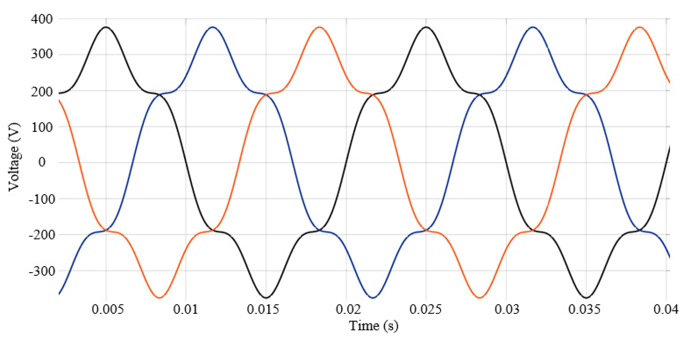
- The voltage waves applied to the stator are deformed, by superposing over the fundamental of a single harmonic, with orders from the series k ∊ {5, 7, 11, 13, 17, 19}, and having percentage levels among the values γVk ∊ {5%, 10%, 15%, 20%, 25%, 30%}, above the rated value of the voltage.
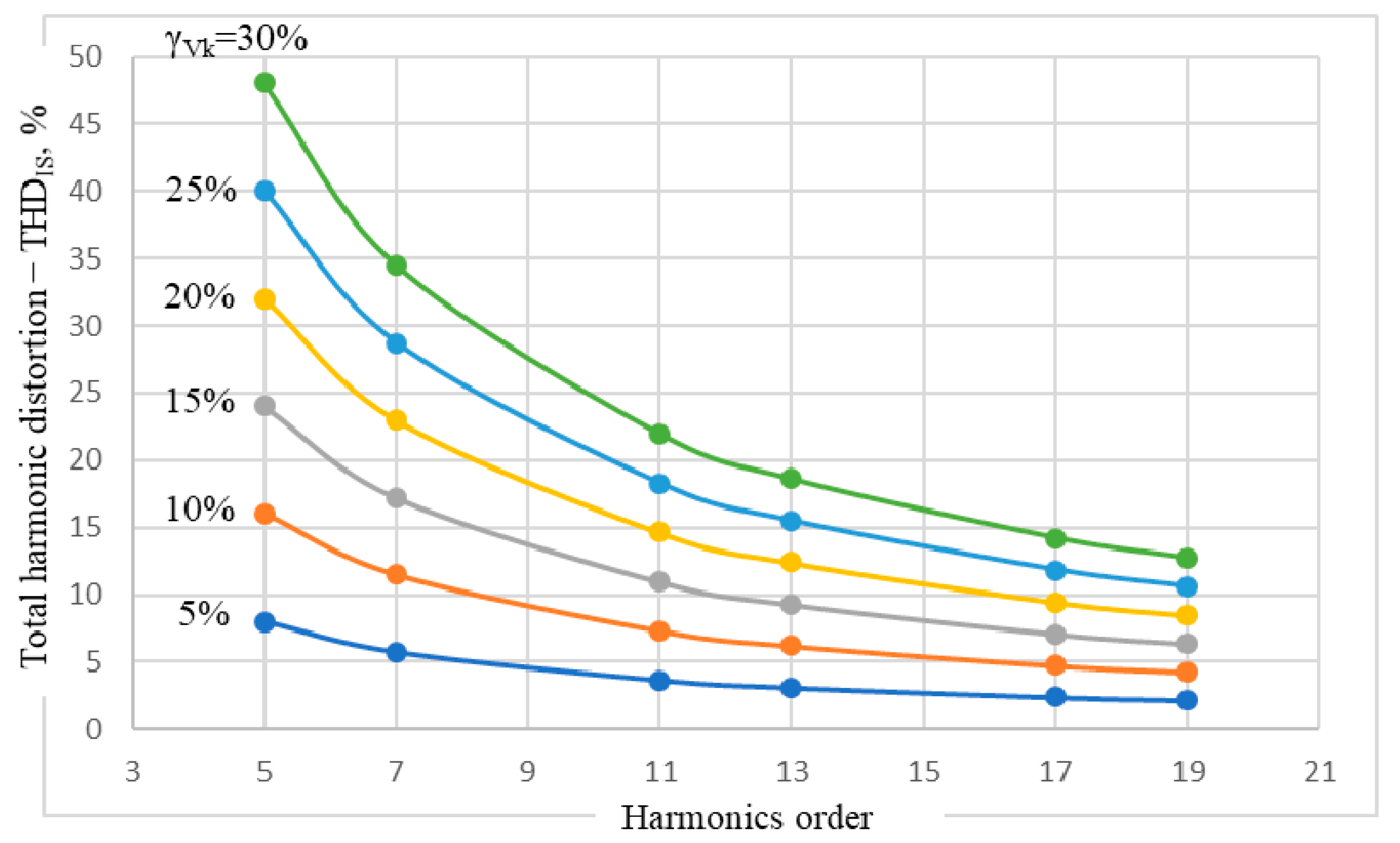
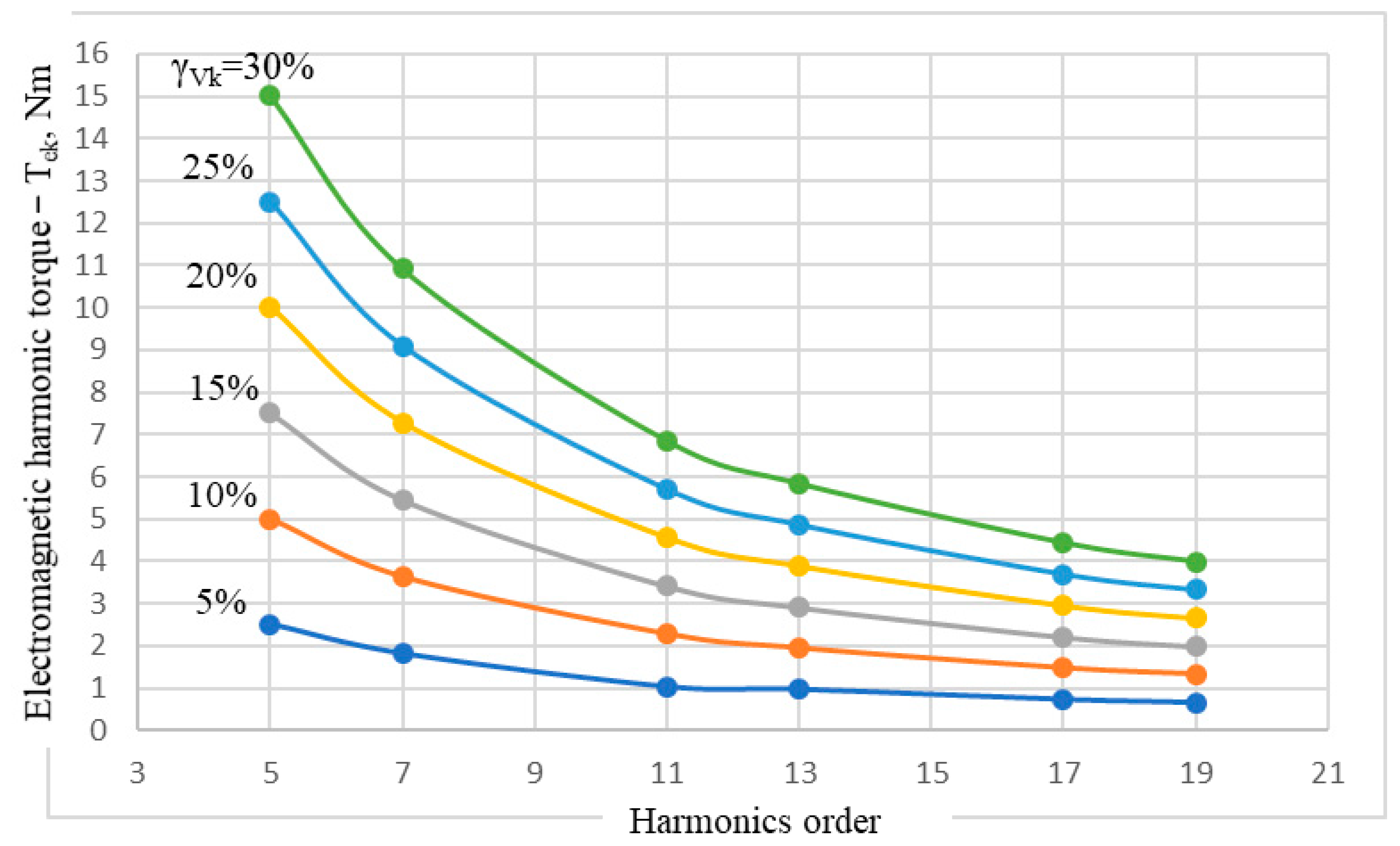
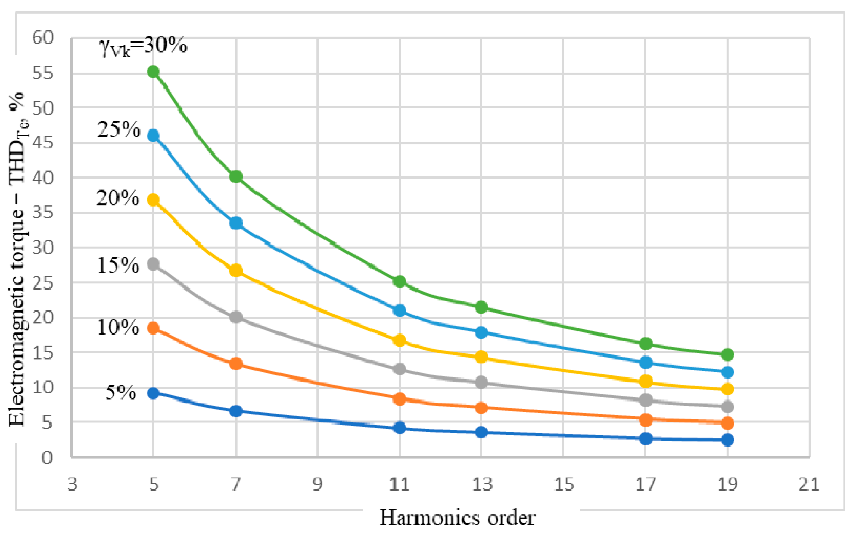
- Solving the situations considered above on the physical model of the IM, the levels of the harmonics of the stator current, corresponding to those of the injected voltage, are followed. Moreover, the total harmonic distortion (THD) of the stator current, of the electromagnetic torque and its THD, the PF, and the IM efficiency are monitored as well.
3. Results
4. Discussion
4.1. THD of the Stator Current
4.2. The Electromagnetic Torque of the IM
4.3. THD of the IM Electromagnetic Torque
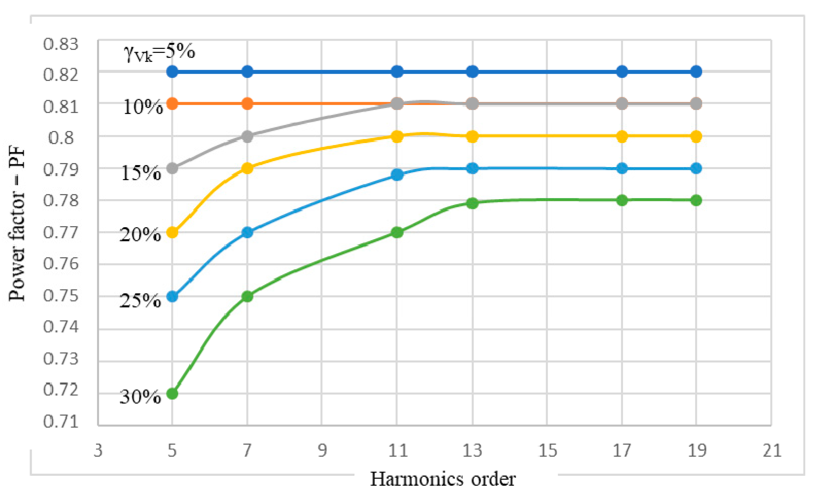
4.4. Power Factor of the IM
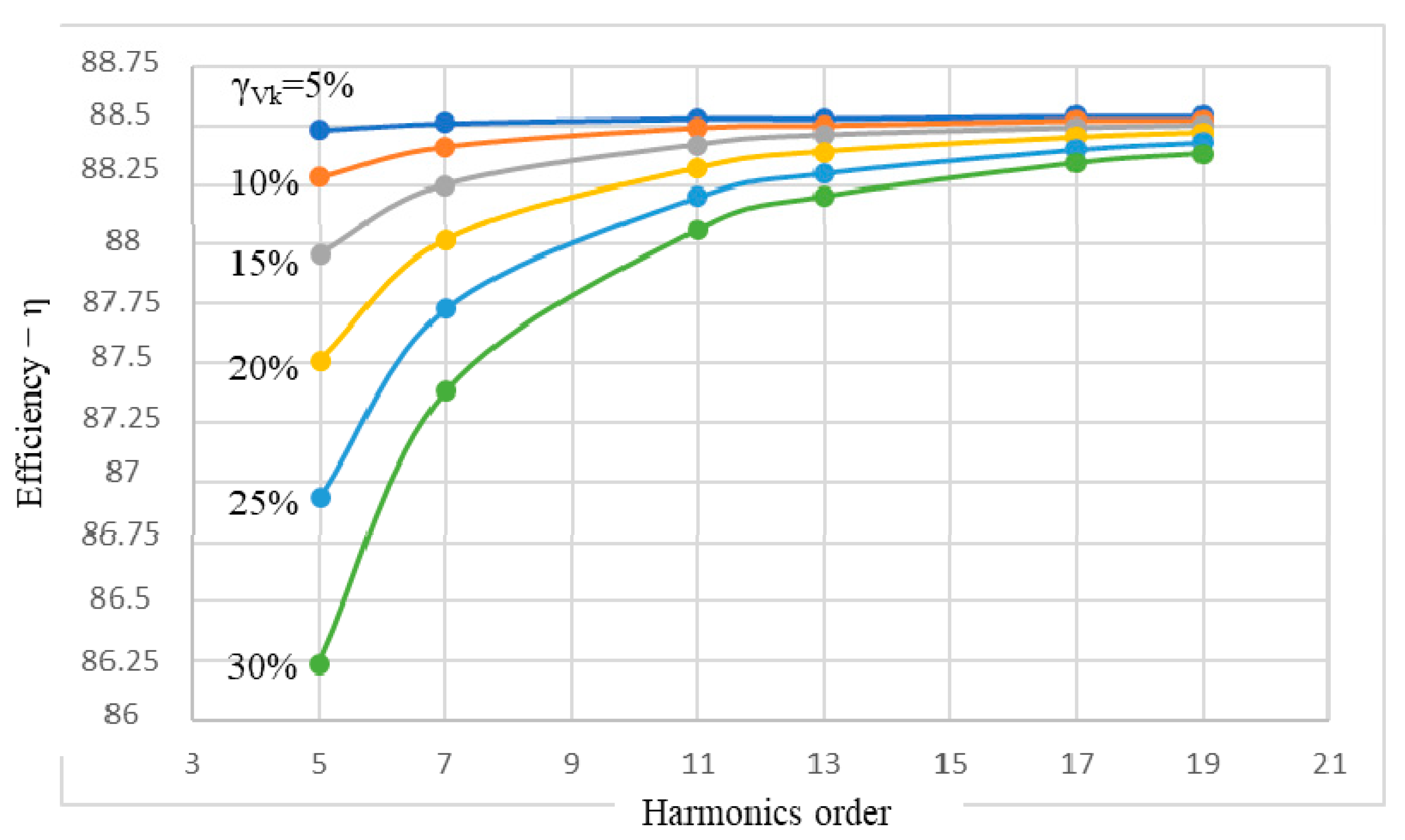
4.5. The Efficiency of the IM
5. Conclusions
- Deformation of the voltage waves applied to the stator, by overlaying a single harmonic, with different orders and percentage levels, so that the total RMS value of the voltage is less than or equal to the rated value.
- Introduction of two or even more harmonics into the harmonic content of the voltage wave simultaneously.
- The study of the IM behavior in harmonics at different percentage loads such as 25%, 50%, and 75%.
- Adaptation of the current physical model of the IM to track the effects of saturation on the current harmonics developed in the motor. The present study is a reference to assess the consequences of saturation.
Author Contributions
Funding
Acknowledgments
Conflicts of Interest
References
- Waide, P. , Brunner, C.U. Energy-Efficiency Policy Opportunities for Electric Motor-Driven Systems; Internationnal Energy Agency: Paris, France, 2011. [Google Scholar]
- Santos, V.S.; Eras, J.J.C.; Gutierrez, A.S.; Ulloa, M.J.C. Assessment of the energy efficiency estimation methods on induction motors considering real-time monitoring. Measurement 2019, 136, 237–247. [Google Scholar] [CrossRef]
- Debruyne, C.; Lieven, V.; Jan, D. Harmonic effects on induction and line start permanent magnet machines. EEMODS 2013. [Google Scholar]
- Singh, G. A research survey of induction motor operation with non-sinusoidal supply wave forms. Electr. Power Syst. Res. 2005, 75, 200–213. [Google Scholar] [CrossRef]
- Dugan, R.C.; McGranaghan, M.F.; Santoso, S.; Beaty, H.W. Electrical Power Systems Quality, 2nd ed.; McGraw Hill Companies: New York, NY, USA, 2004. [Google Scholar]
- Rata, M.; Rata, G. Study solution of induction motor dynamic braking. In Proceedings of the 2016 International Conference on Development and Application Systems (DAS), Suceava, Romania, 19–21 May 2016; pp. 33–37. [Google Scholar]
- Rata, G.; Rata, M.; Graur, I.; Milici, D.L. Induction Motor Speed Estimator Using Rotor Slot Harmonics. Adv. Electr. Comput. Eng. 2009, 9, 70–73. [Google Scholar] [CrossRef]
- Bednarz, S.; Dybkowski, M. Estimation of the Induction Motor Stator and Rotor Resistance Using Active and Reactive Power Based Model Reference Adaptive System Estimator. Appl. Sci. 2019, 9, 5145. [Google Scholar] [CrossRef] [Green Version]
- Salomon, C.P.; Santana, W.; Lambert-Torres, G.; Da Silva, L.B.; Bonaldi, E.L.; De Oliveira, L.; Da Silva, L.E.B. Comparison among Methods for Induction Motor Low-Intrusive Efficiency Evaluation Including a New AGT Approach with a Modified Stator Resistance. Energies 2018, 11, 691. [Google Scholar] [CrossRef] [Green Version]
- Wang, K.; Huai, R.; Yu, Z.; Zhang, X.; Li, F.; Zhang, L. Comparison Study of Induction Motor Models Considering Iron Loss for Electric Drives. Energies 2019, 12, 503. [Google Scholar] [CrossRef] [Green Version]
- Debruyne, C.; Desmet, J.; Derammelaere, S.; Vandevelde, L. Derating factors for direct online induction machines when supplied with voltage harmonics: A critical view. In Proceedings of the 2011 IEEE International Electric Machines & Drives Conference (IEMDC), Niagara Falls, ON, Canada, 15–18 May 2011; pp. 1048–1052. [Google Scholar]
- Debruyne, C.; Corne, B.; Sergeant, P.; Desmet, J.; Vandevelde, L. Evaluation of the additional loss due to supply voltage distortion in relation to induction motor efficiency rating. In Proceedings of the 2015 IEEE International Electric Machines & Drives Conference (IEMDC), Coeur d’Alene, ID, USA, 10–13 May 2015; pp. 1881–1887. [Google Scholar]
- Zhang, D.; An, R.; Wu, T. Effect of voltage unbalance and distortion on the loss characteristics of three-phase cage induction motor. IET Electr. Power Appl. 2018, 12, 264–270. [Google Scholar] [CrossRef]
- Mirzapour, O.; Karimi-Arpanahi, S.; Oraee, H. Evaluating Grid Harmonics Effect on Induction Motor Using Reduced Thermal Model. In Proceedings of the 2018 Smart Grid Conference (SGC), Sanandaj, Iran, 28–29 November 2018; pp. 1–5. [Google Scholar]
- Sousa, V.; Viego, P.R.; Gomez, J.R.; Quispe, E.C.; Balbis, M. Estimating induction motor efficiency under no-controlled conditions in the presences of unbalanced and harmonics voltages. In Proceedings of the 2015 CHILEAN Conference on Electrical, Electronics Engineering, Information and Communication Technologies (CHILECON), Santiago, Chile, 28–30 October 2015; pp. 567–572. [Google Scholar]
- Monteagudo, F.E.L.; Carralero, L.R.; Telles, A.B.; Rivas, C.R.; Elías, M.E.G.; Varela, R.V.; García, G.E.; Ibarra, D.A.; Hernández, R.F.I. Incidence of harmonic in asynchronous three-phase motors. Procedia Eng. 2012, 35, 14–21. [Google Scholar] [CrossRef] [Green Version]
- Kumar, D. Performance Analysis of Three-Phase Induction Motor with AC Direct and VFD. IOP Conf. Series: Mater. Sci. Eng. 2018, 331, 012025. [Google Scholar] [CrossRef]
- Agamloh, E.; Peele, S.; Grappe, J. An experimental evaluation of the effect of voltage distortion on the performance of induction motors. In Proceedings of the Conference Record of 2012 Annual IEEE Pulp and Paper Industry Technical Conference (PPIC), Portland, OR, USA, 17–21 June 2012; pp. 1–7. [Google Scholar]
- Phumiphak, P.; Chat-Uthai, C. Nonintrusive Method for Estimating Field Efficiency of Inverter-Fed Induction Motor Using Measured Values. In Proceedings of the 2008 IEEE International Conference on Sustainable Energy Technologies, Singapore, 24–27 November 2008; pp. 580–583. [Google Scholar]
- Santos, V.S.; Felipe, P.R.V.; Sarduy, J.R.G.; Lemozy, N.A.; Jurado, A.; Quispe, E.C. Procedure for Determining Induction Motor Efficiency Working Under Distorted Grid Voltages. IEEE Trans. Energy Convers. 2014, 30, 331–339. [Google Scholar] [CrossRef]
- Chirindo, M.; Khan, M.A.; Barendse, P. Considerations for Nonintrusive Efficiency Estimation of Inverter-Fed Induction Motors. IEEE Trans. Ind. Electron. 2015, 63, 741–749. [Google Scholar] [CrossRef]
- Djurovic, S.; Rodriguez, D.S.V.; Smith, A. Supply Induced Interharmonic Effects in Wound Rotor and Doubly-Fed Induction Generators. IEEE Trans. Energy Convers. 2015, 30, 1397–1408. [Google Scholar] [CrossRef]
- Yacamini, R.; Chang, S.C. Noise and vibration from induction machines fed from harmonic sources. IEEE Trans. Energy Convers. 1995, 10, 286–292. [Google Scholar] [CrossRef]
- MathWorks. Available online: https://www.mathworks.com/help/physmod/sps/powersys/ref/asynchronousmachine.html (accessed on 15 January 2020).


| Symbol | Parameter | Value |
|---|---|---|
| Pn | Rated power | 4 kW |
| Vn,RMS | Rated line-to-line voltage | 400 V |
| f | Frequency | 50 Hz |
| Nn | Rated speed | 1430 rpm |
| Rs | Stator resistance | 1.405 Ω |
| Lls | Stator leak inductance | 0.005839 H |
| Rr’ | Rotor resistance | 1.395 Ω |
| Llr’ | Rotor leak inductance | 0.005839 H |
| Lm | Mutual inductance | 0.1722 |
| J | Inertia | 0.0131 kgm2 |
| F | Friction factor | 0.002985 Nms |
| p | Pole pairs | 2 |
| PFn | Rated power factor | 0.82 |
| ηn | Rated efficiency | 88.5% |
| Parameter | Motor Load, % | |||
|---|---|---|---|---|
| 25% | 50% | 75% | 100% | |
| Stator Current—IS,RMS, A | 4.44 | 5.29 | 6.5 | 7.94 |
| Rotor Current—IR,RMS, A | 1.94 | 1.74 | 3.1 | 9.38 |
| Rotor Speed—N, rpm | 1484 | 1468 | 1452 | 1435 |
| Electromagnetic Torque—Te, Nm | 7.13 | 13.81 | 20.47 | 27.15 |
| Active Power—P, kW | 1.2 | 2.28 | 3.39 | 4.53 |
| Reactive Power—Q, kVAr | 2.83 | 2.86 | 2.96 | 3.12 |
| Power Factor—PF | 0.39 | 0.62 | 0.75 | 0.82 |
| Efficiency—η, % | 86.11 | 89.75 | 89.68 | 88.54 |
| Harmonic Order k | Parameter | Voltage Harmonics Level of Fundamental, γVk, % | |||||
|---|---|---|---|---|---|---|---|
| 5% | 10% | 15% | 20% | 25% | 30% | ||
| 5 | Stator current—IS,RMS, A | 7.96 | 8.04 | 8.17 | 8.34 | 8.56 | 8.82 |
| THDIS, % | 8.01 | 16.04 | 24.05 | 32.05 | 40.05 | 48.03 | |
| Rotor current—IR,RMS, A | 9.4 | 9.46 | 9.55 | 9.69 | 9.85 | 10.07 | |
| Electromagnetic harmonic torque—Tek, Nm | 2.51 | 5.01 | 7.51 | 10.01 | 12.515 | 15.02 | |
| Electromagnetic torque—THDTe, % | 9.22 | 18.44 | 27.66 | 36.87 | 46.09 | 55.31 | |
| Active power—P, kW | 4.53 | 4.54 | 4.56 | 4.58 | 4.61 | 4.65 | |
| Reactive power—Q, kVAr | 3.14 | 3.2 | 3.31 | 3.47 | 3.66 | 3.91 | |
| Power factor—PF | 0.82 | 0.81 | 0.79 | 0.77 | 0.75 | 0.72 | |
| Efficiency—η, % | 88.48 | 88.28 | 87.96 | 87.51 | 86.93 | 86.24 | |
| 7 | Stator current—IS,RMS, A | 7.95 | 7.99 | 8.05 | 8.14 | 8.25 | 8.39 |
| THDIS, % | 5.74 | 11.49 | 17.24 | 22.99 | 28.74 | 34.5 | |
| Rotor current—IR,RMS, A | 9.39 | 9.42 | 9.47 | 9.54 | 9.64 | 9.75 | |
| Electromagnetic harmonic torque—Tek, Nm | 1.82 | 3.64 | 5.46 | 7.28 | 9.1 | 10.92 | |
| Electromagnetic torque—THDTe, % | 6.7 | 13.4 | 20.11 | 26.81 | 33.51 | 40.22 | |
| Active power—P, kW | 4.53 | 4.53 | 4.54 | 4.55 | 4.57 | 4.59 | |
| Reactive power—Q, kVAr | 3.13 | 3.18 | 3.26 | 3.37 | 3.51 | 3.68 | |
| Power factor—PF | 0.82 | 0.81 | 0.8 | 0.79 | 0.77 | 0.75 | |
| Efficiency—η, % | 88.51 | 88.41 | 88.25 | 88.02 | 87.73 | 87.38 | |
| 11 | Stator current—IS,RMS, A | 7.94 | 7.96 | 7.98 | 8.02 | 8.07 | 8.13 |
| THDIS, % | 3.66 | 7.32 | 10.98 | 14.64 | 18.3 | 21.96 | |
| Rotor current—IR,RMS, A | 9.39 | 9.4 | 9.43 | 9.45 | 9.49 | 9.54 | |
| Electromagnetic harmonic torque—Tek, Nm | 1.04 | 2.285 | 3.425 | 4.57 | 5.71 | 6.85 | |
| Electromagnetic torque—THDTe, % | 4.21 | 8.41 | 12.62 | 16.82 | 21.03 | 25.23 | |
| Active power—P, kW | 4.53 | 4.53 | 4.53 | 4.54 | 4.54 | 4.55 | |
| Reactive power—Q, kVAr | 3.13 | 3.16 | 3.21 | 3.28 | 3.37 | 3.48 | |
| Power factor—PF | 0.82 | 0.81 | 0.81 | 0.8 | 0.79 | 0.77 | |
| Efficiency—η, % | 88.53 | 88.49 | 88.42 | 88.32 | 88.2 | 88.06 | |
| 13 | Stator current—IS,RMS, A | 7.94 | 7.95 | 7.97 | 8 | 8.03 | 8.07 |
| THDIS, % | 3.09 | 6.19 | 9.29 | 12.39 | 15.49 | 18.59 | |
| Rotor current—IR,RMS, A | 9.38 | 9.4 | 9.41 | 9.43 | 9.46 | 9.49 | |
| Electromagnetic harmonic torque—Tek, Nm | 0.975 | 1.95 | 2.92 | 3.895 | 4.87 | 5.84 | |
| Electromagnetic torque—THDTe, % | 3.59 | 7.17 | 10.76 | 14.34 | 17.93 | 21.52 | |
| Active power—P, kW | 4.53 | 4.53 | 4.53 | 4.53 | 4.54 | 4.54 | |
| Reactive power—Q, kVAr | 3.12 | 3.15 | 3.19 | 3.25 | 3.33 | 3.42 | |
| Power factor—PF | 0.82 | 0.81 | 0.81 | 0.8 | 0.79 | 0.78 | |
| Efficiency—η, % | 88.53 | 88.5 | 88.46 | 88.39 | 88.3 | 88.2 | |
| 17 | Stator current—IS,RMS, A | 7.94 | 7.94 | 7.96 | 7.97 | 7.99 | 8.02 |
| THDIS, % | 2.36 | 4.73 | 7.1 | 9.47 | 11.85 | 14.22 | |
| Rotor current—IR,RMS, A | 9.38 | 9.39 | 9.4 | 9.41 | 9.43 | 9.45 | |
| Electromagnetic harmonic torque—Tek, Nm | 0.74 | 1.48 | 2.22 | 2.96 | 3.7 | 4.44 | |
| Electromagnetic torque—THDTe, % | 2.72 | 5.45 | 8.17 | 10.89 | 13.62 | 16.34 | |
| Active power—P, kW | 4.53 | 4.53 | 4.53 | 4.53 | 4.53 | 4.54 | |
| Reactive power—Q, kVAr | 3.12 | 3.14 | 3.17 | 3.22 | 3.28 | 3.35 | |
| Power factor—PF | 0.82 | 0.81 | 0.81 | 0.8 | 0.79 | 0.78 | |
| Efficiency—η, % | 88.54 | 88.52 | 88.49 | 88.45 | 88.4 | 88.34 | |
| 19 | Stator current—IS,RMS, A | 7.94 | 7.94 | 7.95 | 7.96 | 7.98 | 8 |
| THDIS, % | 2.12 | 4.24 | 6.36 | 8.48 | 10.6 | 12.72 | |
| Rotor current—IR,RMS, A | 9.38 | 9.39 | 9.4 | 9.41 | 9.42 | 9.44 | |
| Electromagnetic harmonic torque—Tek, Nm | 0.665 | 1.33 | 1.995 | 2.66 | 3.325 | 3.99 | |
| Electromagnetic torque—THDTe, % | 2.45 | 4.90 | 7.35 | 9.80 | 12.24 | 14.69 | |
| Active power—P, kW | 4.53 | 4.53 | 4.53 | 4.53 | 4.53 | 4.53 | |
| Reactive power—Q, kVAr | 3.12 | 3.14 | 3.17 | 3.21 | 3.26 | 3.33 | |
| Power factor—PF | 0.82 | 0.81 | 0.81 | 0.8 | 079 | 0.78 | |
| Efficiency—η, % | 88.54 | 88.52 | 88.5 | 88.47 | 88.43 | 88.38 | |
| Harmonic Order k | THDIS/γVk |
|---|---|
| 5 | 1.600 |
| 7 | 1.149 |
| 11 | 0.732 |
| 13 | 0.619 |
| 17 | 0.473 |
| 19 | 0.424 |
© 2020 by the authors. Licensee MDPI, Basel, Switzerland. This article is an open access article distributed under the terms and conditions of the Creative Commons Attribution (CC BY) license (http://creativecommons.org/licenses/by/4.0/).
Share and Cite
Beleiu, H.G.; Maier, V.; Pavel, S.G.; Birou, I.; Pică, C.S.; Dărab, P.C. Harmonics Consequences on Drive Systems with Induction Motor. Appl. Sci. 2020, 10, 1528. https://doi.org/10.3390/app10041528
Beleiu HG, Maier V, Pavel SG, Birou I, Pică CS, Dărab PC. Harmonics Consequences on Drive Systems with Induction Motor. Applied Sciences. 2020; 10(4):1528. https://doi.org/10.3390/app10041528
Chicago/Turabian StyleBeleiu, Horia Gheorghe, Virgil Maier, Sorin Gheorghe Pavel, Iulian Birou, Constantin Sorin Pică, and Pompei Cosmin Dărab. 2020. "Harmonics Consequences on Drive Systems with Induction Motor" Applied Sciences 10, no. 4: 1528. https://doi.org/10.3390/app10041528
APA StyleBeleiu, H. G., Maier, V., Pavel, S. G., Birou, I., Pică, C. S., & Dărab, P. C. (2020). Harmonics Consequences on Drive Systems with Induction Motor. Applied Sciences, 10(4), 1528. https://doi.org/10.3390/app10041528


