1. Introduction
The direct torque control (DTC) was first proposed for control of inverter-fed induction motors (IMs) by Takahashi et al. [
1] and Depenbrock [
2] decades ago. In the conventional DTC, an active voltage vector or a zero-voltage vector is applied to electric motors in one control action and the voltage vector is determined through a switching table based on the output of the flux linkage and torque hysteresis comparators. The conventional DTC possesses advantages of simple realization and robustness; however, its high torque ripples and flux ripples are critical drawbacks caused by the variable switching frequency.
Many previous studies have been dedicated to resolve the high torque ripple problem of DTC. For example, the duty-cycle-based DTC methods were introduced [
3,
4,
5], where one active voltage vector and one zero voltage vector are applied to motors in a fixed cycle to achieve better torque control. In calculation of time duration, only torque ripple reduction is considered but not flux linkage and therefore, for operating points with high flux linkage, the reduction in flux linkage ripple may not be effective. Consequently, this may result in high current harmonics. In [
6,
7,
8], the space vector modulation (SVM) is employed in DTC. The voltage vector is decided by varying the load angle which is obtained through an estimator. The torque ripple is reduced through the space vector modulation direct torque control (SVM-DTC) with fixed switching frequency; however, the dynamic response is weaker than the conventional DTC. In the work conducted by Świerczyński regarding SVM-DTC [
9], the
α- and
β-components of the voltage command is calculated through the magnitude and angle of the flux linkage vector. However, the estimation of flux linkage angle often contains errors that are possibly caused by the noise of the current, flux linkage estimator, or even motor vibration. This would affect the calculation of voltage command and cause fluctuation, which further produces torque ripple. In [
10], the relationship between electromagnetic torque and voltage vector is analyzed. Based on the analysis, minimum torque ripple and flux ripple in steady state, and fast dynamic response can be obtained by precise control of the magnitude, phase, and time duration of the voltage vector applied to the motor. However, the control algorithm could be too complex for a digital signal processor (DSP) to realize.
In summary, there would still be room for improvement from the above-mentioned studies:
- (1)
Torque ripples may be effectively reduced but not flux linkage ripple that can result in significant iron loss. Moreover, dynamic response may be sacrificed.
- (2)
Both torque ripple and flux linkage ripple can be reduced, and dynamic response is maintained; however, the control algorithm may be so complex that the implementation could be difficult.
Therefore, this paper proposes a simple approach to determine the voltage command vector for decreasing the torque ripple and improving the response based on SVM-DTC. This proposed method is called the “revised SVM-DTC (rSVM-DTC)”. In this work, the performance in both transient state and steady state is investigated. Based on [
10], the relationship between the voltage vector and the torque ripple for a permanent magnet synchronous motor (PMSM) driven with SVM-DTC is further analyzed. Through the analysis, a proper voltage command vector determined by the proposed method is fed to the voltage source inverter (VSI) for torque ripple reduction. Unlike other methods that rely on both flux linkage magnitude and angle for calculation of voltage command [
6,
7,
8,
9], the proposed method does not require the flux linkage angle for calculation of the magnitude of voltage command. This significantly reduces the voltage command fluctuation (will be detailed later). The proposed method is simple and easily implemented. This is treated as the major contribution in this paper.
The result is compared to that of the conventional SVM-DTC. Moreover, it is known that torque ripple can be brought down with higher switching frequency [
10], but this would also increase switching loss. Thus, another target of the proposed method is to achieve torque ripple reduction while keeping a low switching frequency.
2. Torque Analysis and Proposed DTC
In order to simultaneously control the flux linkage and torque in a precise manner, two active voltage vectors and two zero voltage vectors are applied in every control cycle so that any voltage vector can be composed through space vector modulation [
11]. This is the conventional SVM-DTC. By doing so, the magnitude and phase of a voltage vector are adjusted with the objective of obtaining the minimum torque ripples in steady state. In this section, the effect of voltage vector on both the torque and flux linkage of the PMSM is investigated.
2.1. Flux Linkage Synchronous Frame
The relationship between the rotor synchronous (
d-
q) frame, which is usually applied to field oriented control (FOC), and the flux linkage synchronous (
f-
t) frame is shown in
Figure 1 [
12,
13], where the angular displacement of
f-axis with respect to
d-axis is
. In the
f-
t frame, the
f-axis is aligned with the stator flux linkage, and the
t-axis leads the
f-axis by 90
. Referring to
Figure 1, the flux linkage, stator current, and voltage can be transformed to the
f-
t frame, as given by
where
F can be considered as flux linkage, stator current or voltage.
2.2. Mathematical Model of PMSM and Relationship between Voltage Vector and Torque
The PMSM voltage and current equations in the
d-
q frame can be respectively expressed as [
14]
and
where
are
d-
q-axis voltage,
are
d-
q-axis current,
are
d-
q-axis flux linkage,
is flux linkage due to permanent magnet (PM),
is electric angular speed,
are
d-
q-axis inductance, and
is stator resistance.
Substituting Equation (3) into (2) with a rearrangement yields
Base on Equation (4), for digital implementation of the DTC, the discrete flux linkages of the motor in the
d-q frame at time increment
can be calculated by
where
is the period of one control action or sampling, and all the symbols with subscript “
k” or “(
k + 1)” indicate the physical quantities that are obtained at time increment
or
, respectively.
By substituting Equations (5) and (6) into (3), the
d-q axis current at
can be obtained as
The electromagnetic torque
of the PMSM can obtained as [
15,
16]
where
p is number of pole pairs,
is armature current and
is stator flux linkage vector whose
d- and
q-axis components are, respectively,
.
By substituting Equations (5)–(8) into (9), the torque at
can be calculated and expressed as
where
where
and
are the torque components at
, and
to
are the four terms that cause torque variations affecting the torque at
.
The physical meaning of these four terms, namely to , are explained as follows:
- (1)
In Equations (13) and (14), and are the torque reduction terms due to impedance, and they are proportional to and , respectively.
- (2)
is the variation of torque involving the voltage vector. The output torque is influenced by the
term during the period that an active voltage vector is applied to the motor but not during the period with a zero-voltage vector. Based on Equation (15), the relationship between
and motor voltage vector at
, can be obtained as follows:
where
is arithmetic operator representing the Hadamard product, and
is a vector expressed as follows:
- (3)
is the variation of torque involving flux linkage. The torque is influenced by this term more significantly when the flux linkage becomes larger with a heavier load applied to the motor [
16,
17]. Additionally, when the motor is operated at a high speed, the amplitude of
would also become large. Based on Equation (16), the relationship between
and
can be obtained as follows:
In what follows, and are respectively called “the third torque variation term” and “the fourth torque variation term”.
2.3. Proposed DTC for PMSM
As previously discussed, it is considered that the error in flux linkage angle would influence the accuracy of the voltage vector command and consequently affect the torque ripple. In order to improve this problem, the
f-
t frame was used to develop the new algorithm to generate a proper voltage vector command for the VSI. The solution proposed in this paper is to decouple the mutual effect between the voltage magnitude and flux linkage angle so that the voltage command will not be affected by the error of flux linkage angle. For the vectors shown in
Figure 2,
is the flux linkage at
,
is the flux linkage at
(i.e.,
), the angle
between
and
is the variation of the load angle,
is the variation of flux linkage, and
is angle of flux linkage variation referring to
f-axis.
From
Figure 2, the magnitude of motor voltage
can be derived by applying the law of cosines, as given by [
18]
where
is the period of pulse-width modulation (PWM). Additionally, the phase of the voltage
is the same as
[
18] and can be formulated with the law of sines as follows:
where
is the angle between voltage vector and
f-axis. In
Figure 3, the angle between voltage vector and
-axis can thus be obtained as
where
is phase of flux linkage vector in
- frame.
Based on the conventional SVM-DTC scheme shown in
Figure 4 [
19], the proposed method in this paper, the rSVM-DTC as previously mentioned, replaces the dashed area by the diagram shown in
Figure 5. It should be noted that the flux linkage
in
Figure 5 can be simply obtained by
and
in
Figure 4. Note that
in
Figure 5 is
in
Figure 3. As shown in
Figure 5, there is no mutual influence between the magnitude of voltage vector and flux linkage angle. The angle of voltage vector referring to
-axis,
, is the sum of the angle of flux linkage,
and
. The voltage command vector is calculated by the proposed architecture shown in
Figure 5 to improve the torque ripple of the PMSM.
3. Computer Simulation
In this section, the effectiveness of the proposed method, rSVM-DTC was first verified by a simulation conducted with Simulink/MATLAB. The parameters of the PMSM for all the simulations are shown in
Table 1. The performance of the proposed method was investigated and then compared with the conventional SVM-DTC proposed in [
8]. In addition, two different switching frequencies were applied to the conventional SVM-DTC, namely 10 kHz and 11 kHz, to investigate the effect of switching frequency on torque ripple, even with such a small increment. For simplicity, the conventional SVM-DTC methods with 10 kHz and 11 kHz are respectively referred to as cSVM-DTC1 and cSVM-DTC2 in what follows.
Note that 10 kHz can be treated as a common switching frequency for motor drives (e.g., with insulated-gate bipolar transistors, IGBTs) to avoid high switching loss, and this frequency was used in this study. Some transistors (e.g., silicon carbide metal-oxide semiconductor field-effect transistors, SiC MOSFETs) can be switched at a higher frequency but the cost may be increased if such devices are employed. Another objective of the proposed method is to make use of a low switching frequency for motor drive so that less expensive transistors can be used, and less switching loss can be achieved, while keeping the torque ripple low. For 11 kHz, it was chosen only for comparison. The switching frequencies were swept from low to high and it was found that the motor torque ripple at 11 kHz switching with conventional SVM-DTC was similar to that of the proposed method at 10 kHz. This is the reason why 10 kHz and 11 kHz were used and compared.
In the steady state simulation, as the PMSM operated at 2500 rpm with a 40 Nm rated load, the torque ripples for cSVM-DTC1, cSVM-DTC2 and the proposed rSVM-DTC were 27.5%, 14.8% and 17.3%, respectively; the torque waveforms for the three cases are shown in
Figure 6,
Figure 7 and
Figure 8. It can be observed that the torque ripples for the proposed method were smaller than that of cSVM-DTC1 and similar to that of cSVM-DTC2 (at a higher switching frequency, 11 kHz).
As shown in
Figure 9,
Figure 10 and
Figure 11, the variation of magnitude of voltage command vector for cSVM-DTC1 was larger than that of the proposed rSVM-DTC and the higher-switching-frequency cSVM-DTC2. Referring to
Figure 6,
Figure 7 and
Figure 8, it can be seen that lower torque ripple could be obtained when the fluctuation of the magnitude of the voltage command vector was smaller.
The torque ripple can be analyzed based on Equations (13)–(16). As previously mentioned and indicated in (15), the third torque variation term
can be affected by voltage vector.
Figure 12,
Figure 13 and
Figure 14 show the sole contribution of
in (15) calculated using the simulation results. As can be seen, the torque component varies when active voltage vector is applied but is kept at zero when zero vector is applied. Obviously, the number of switchings within a period depends also on the switching frequency. In order to analyze the influence of the third torque variation term, the integral of this torque component in one control cycle was conducted. As shown in
Figure 15,
Figure 16 and
Figure 17, the third torque variation term provoked significant torque ripple for cSVM-DTC1 but with less impact on cSVM-DTC2 and the proposed rSVM-DTC.
As indicated in Equation (16), the fourth torque variation term is related to flux linkage, which is in turn affected by voltage vector. That is, the fourth torque variation is also influenced by the voltage vector, which causes flux ripple. As can be observed in
Figure 18,
Figure 19 and
Figure 20, the torque variations due to the fourth term for the proposed rSVM-DTC and cSVM-DTC2 method were milder than that for cSVM-DTC1. Nevertheless, their magnitude was much smaller than that of the third torque variation term.
In summary,
Table 2 shows the comparison between the results from the previous simulations for the three methods. As can be seen, the correlation between the torque ripple and the torque variation due to the third term is apparent. This validates the effectiveness of the proposed rSVM-DTC.
4. Hardware-in-the-Loop Test
The hardware-in-the-loop (HIL) toolkit shown in
Figure 21 is designed as a real-time emulator for evaluation of the performance of electric motor drives and controllers. Therefore, the HIL was used to verify the effectiveness of the proposed method. Potential problems can be identified and resolved in the early developmental stage of motor drives by using HIL. In the HIL test, the control performance can be tested in a safe test environment offered to researchers [
20]. Electrical motors are often tested using a dynamometer. However, for measuring torque ripples, a torque sensor with high bandwidth and a suitable mechanical coupling linking the motor shaft and the test-bench would be required. These are not available in the laboratory and therefore the HIL, which is considered to be sufficiently reliable [
20,
21], was employed to test the control performance of the proposed method.
In the HIL, various types of built-in electric motor models can be selected, and the parameters of these motors can be easily set up by users through a provided user interface. The HIL offers physical terminals for six gate driving signals, three-phase current feedback and rotor position feedback (by “virtual” optical encoders, resolvers or others). A DC link voltage can also be set up as required. In this paper, the target motor was a PMSM whose parameters are listed in
Table 1. These parameters can then be input into the HIL as the controlled target, i.e., the “virtual” PMSM with its model. The detailed function and configuration of the HIL can be found in [
22,
23].
In this study, a digital signal processor (DSP), TMS320F28377S was used to implement the proposed algorithm, which was coded in C language. The setup used for the HIL tests is illustrated in
Figure 21. Based on the test platform, the torque ripple and response for different control methods could then be compared.
Figure 22 shows the connections between the DSP and the HIL toolkit. As can be seen, the six PWM signals are produced by the DSP after calculating the voltage command. The three-phase currents, rotor speed and rotor position can also be fed back to the DSP through the wire connections. Therefore, in this HIL test system, the DSP, the control algorithm written into program and loaded to the DSP and the command/feedback signals were “real”, while the motor and inverter were models built into the HIL toolkit and were “virtual”. The motor model was established according to the parameters listed in
Table 1, as previously mentioned. In the HIL toolkit, the load torque is allowed to be programmed such that the load can be applied to the motor model. The motor model would then react to the load condition with the voltage controlled by the DSP.
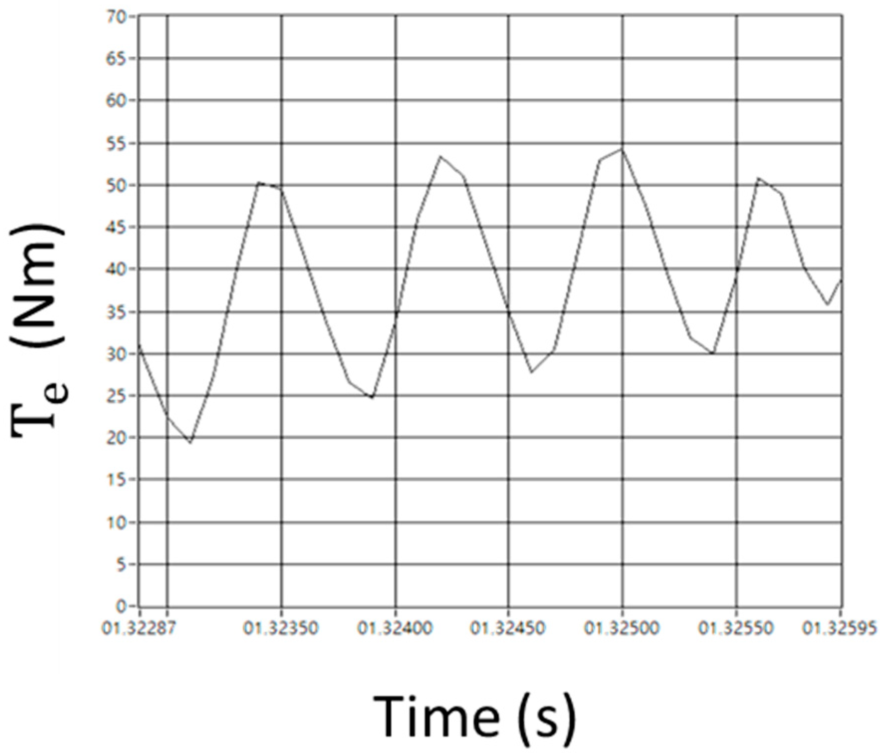
As observed in
Figure 23 and
Figure 24, the torque ripple in cSVM-DTC1 was 35 Nm (87.5%), and that for the proposed rSVM-DTC was 15 Nm (37.5%). Note that the switching frequency was 10 kHz. The improvement was significant by employing the proposed method. Additionally, it can be noted that the magnitude of torque ripple obtained by the HIL tests was generally greater than that in the simulation. This could be attributed to the fact that the simulation was conducted in an ideal scenario without considering the handling and delay of signals, as might occur in the HIL tests.
The dynamic response of the proposed method was also briefly investigated. The system was suddenly unloaded from 25 Nm to 0 Nm when the motor was operating at 1600 rpm in the steady state. As can be seen in
Figure 25 and
Figure 26, by keeping the same speed controller, the proposed method settled the system to 1600 rpm within 2% speed deviation within 0.7 s, while the conventional SVM-DTC required more than 0.8 s. This was not a significant improvement; however, the objective was torque ripple reduction, which was discussed previously. This indicates that the proposed rSVM-DTC is capable of simultaneously reducing torque ripple and maintaining or improving dynamic performance.


