Article

Application of Zero Average Dynamics and Fixed Point Induction Control Techniques to Control the Speed of a DC Motor with a Buck Converter

by
Fredy E. Hoyos
1,*,
John E. Candelo-Becerra
2 and
Carlos I. Hoyos Velasco
3
1
Faculty of Science, School of Physics, Universidad Nacional de Colombia, Sede Medellín, Carrera 65 No. 59A, 110, Medellín 050034, Colombia
2
Faculty of Mines, Department of Electrical Energy and Automation, Universidad Nacional de Colombia, Sede Medellín, Carrera 80 No. 65-223, Robledo, Medellín 050041, Colombia
3
Istituto Motori IM, Italian National Research Council, Via Guglielmo Marconi, 4, 80125 Napoli, Italy
*
Author to whom correspondence should be addressed.
Appl. Sci. 2020, 10(5), 1807; https://doi.org/10.3390/app10051807
Submission received: 7 February 2020 / Revised: 28 February 2020 / Accepted: 3 March 2020 / Published: 6 March 2020

Abstract

:
Several technological applications require well-designed control systems to induce a desired speed in direct current (DC) motors. Some controllers present saturation in the duty cycle, which generates variable switching frequency and subharmonics. The zero average dynamics and fixed point induction control (ZAD-FPIC) techniques have been shown to reduce these problems; however, little research has been done for DC motors, considering fixed switching frequency, quantization effects, and delays. Therefore, this paper presents the speed control of a DC motor by using a buck converter controlled with the ZAD-FPIC techniques. A fourth-order, non-linear mathematical model is used to describe the system dynamics, which combines electrical and electromechanical physical models. The dynamic response and non-linear system dynamics are studied for different scenarios where the control parameters are changed. Results show that the speed of the motor is successfully controlled when using ZAD-FPIC, with a non-saturated duty cycle presenting fixed switching frequency. Simulation and experimental tests show that the controlled system presents a good performance for different quantization levels, which makes it robust to the resolution for the measurement and type of sensor.

1. Introduction

Direct current (DC) motors are very important electromechanical devices in mechatronic systems, which play a fundamental role in the execution of high precision tasks [1]. With the recent advances in permanent magnet materials, as well as their characteristics, such as being lighter, low cost, and low speed, industrial and residential users have increased their use [2,3]. However, non-linear phenomena, such as bifurcations and chaos, have been observed in many types of motor actuators; hence, the behavior of the controller with different resolutions in the measured signals must be identified [4,5,6].
In [7,8], a sliding-mode control is developed to drive an induction motor without sensors; for this, direct torque control and space vector pulse width modulation (SVPWM) are used, where a sliding mode observer using a dual reference frame motor model is introduced and tested. In [9], an adaptive sliding mode controller for the induction motor speed without mechanical sensors is presented. Also in [10], a robust and adaptable sliding controller is formulated for single-input and single-output (SISO) non-linear systems, with application in a linear induction motor. Some drawbacks of the sliding mode control are [10,11,12] that the control gain is large when the limits of the defined parameters are large; the control input may show chattering, which may cause high frequency; and chattering in the input can cause high energy consumption and wear of mechanical components [13,14]. The quasi-sliding mode control emerged as an alternative solution to the inconveniences of the sliding mode control, while retaining the inherent advantages of its operation. In fact, chattering and high frequency switching of the control signal are avoided.
On the other hand, for experimental tests, the digital signal processor (DSP) offers the following features: greater versatility and flexibility compared to analog designs [15], ease in the implementation of non-linear controllers and advanced control techniques, low power consumption and reduction of external passive components, applications with high switching frequency controllers, and others [16,17,18,19].
The quantization effects of the signals in the experimental test (state variables, the duty cycle, etc.) can cause unwanted oscillations, limit cycles, periodic bands, and chaotic behavior [20,21,22,23]. Additionally, according to [16], where the authors study the dynamic response of controlled systems in digital devices, time delays at controller outputs can cause instability [24]. Likewise, in [20] the limit cycles presented in electronic power converters controlled with digital pulse width modulation (DPWM) are set out. To avoid such oscillations, some conditions are imposed on the control law and quantization limits [20]. The fixed point induction control (FPIC) technique allows the stabilization of unstable orbits, as presented in [25], and also allows the estimation of unknown and variable parameters in power converters [26,27]. The minimum requirements for the digital controller parameters are determined in [17], which include the sampling time and the resolution in the measured variables.
In [28], a dynamic sliding surface is used to apply the zero averaging error dynamics control technique (ZAD) as a quasi-sliding mode alternative. ZAD control is also used for the implementation of a buck inverter in an field-programmable gate array (FPGA), verifying that the ZAD technique with side pulse meets the requirement of fixed switching frequency [29,30]. In [31], the numerical and experimental results obtained by applying digital control implemented in a DSP are presented, using the ZAD-FPIC technique in DC–DC and DC–alternating current (AC) converters. From this study, the bifurcation diagrams calculated numerically in the design stage agree quantitatively with those obtained in the experimental test. In works such as [25,26,27,32], the integration of ZAD and FPIC techniques show good results in variable regulation, using buck converters with resistive and motor loads. The ZAD-FPIC technique has been applied in second-order systems, however there are no bifurcation analyses for the FPIC technique.
All these applications show that the ZAD-FPIC technique integrates well with the buck converter, achieving good regulation and tracking of signals at the output when the load is resistive. In addition, with this technique the chattering problem is avoided and the fixed switching frequency is obtained, which is appropriate for control of motors and electromechanical applications. However, in the case of non-resistive loads, e.g. DC motors, few studies have been carried out [26], creating the need for a detailed study that considers the parameter adjustment of the control law, and the effects of numerical quantization, delays, bifurcations, and chaos behavior. As previously reported in the literature, controllers cause saturation in the duty cycle, creating variable switching frequency and sub-harmonics. This problem has been solved by the applying ZAD-FPIC technique for resistive loads; however, electromechanical systems that consider the quantization effects and delays (to obtain a fixed switching frequency in the switches) have not been used, which are more interesting for industrial applications.
Therefore, this paper shows the application of the ZAD-FPIC technique to control the speed of a DC motor using a buck converter as an electric actuator. Additionally, quantization effects are included in the system variables and bifurcation diagrams are obtained to show the behavior when the control parameters are changed. Some of the advantages of using ZAD-FPIC techniques are that the controller presents a fixed switching frequency, low steady-state error, and robustness for the time delays in the system. In [6], some advantages of using ZAD-FPIC techniques to control the buck converter are shown after comparing this controller to the sliding mode control (SMC) and proportional–integral–derivative (PID) techniques. However, this technique is not robust to changes in the system parameters, and the real-time processing requires a high sampling rate and synchronization of signal sensing with a centered pulse width modulation (CPWM) output [33]. Additionally, the design of the controller becomes very complicated when it is used to control higher order systems (more than 6 linear differential equations).
Hence, to present the development of this control application, the paper is divided into four more sections. Section 2 presents the materials and methods used in the research, as well as the mathematical modelling required to design the controller using the ZAD-FPIC technique and to perform the closed loop control simulations. Section 3 includes the results and analysis of the different simulation and experimental tests performed with the proposed changes in the control parameters. Finally, Section 4 ends the paper presenting the conclusions.

2. Materials and Methods

Figure 1 shows the block diagram of the studied system, which is divided into software and hardware. In particular, from system schematics it is shown that the control implementation includes the hardware part with physical and electronic components, while the software part uses a DSP to acquire/process signals and to implement the control technique.
The hardware consists of a permanent magnet DC motor that has the following characteristics: nominal power of 250 W, supply voltage of 42 V, nominal current of 6 A, and maximum speed of 4000 RPM. To measure the speed of the motor ( W m ), an encoder with a rating of 1000 pulses per revolution was used. For sensing of the state variables, namely the capacitor voltage ( υ c ), inductor current ( i L ), and a motor armature current ( i a ), some precision resistors were used. The digital part is developed using the DS1104 board in dSPACE [34,35], in which the ZAD-FPIC technique is implemented. The output of the centered pulse width modulation (CPWM) is calculated in real time by the DS1104.
The state variables υ c , i L , and i a arrive at the controller through the 12-bit analog–digital (ADC) inputs. The controlled variable W m is measured by an encoder that has 28 bits. All these variables are acquired at a sampling rate of 6 kHz. The control block admits the constant parameters defined for the DC electric motor, buck converter, and the ZAD-FPIC technique. The last required parameters are related to the time constants and the dynamics of the error that are imposed on the control system, for example K S 1 , K S 2 , and K S 3 as described in following sections. During each sampling period, the microprocessor in the DS1104 board computes the duty cycle, namely d , with 10-bit resolution, along with its equivalent in the centered pulse width modulation (CPWM) signal for control gate of the metal oxide semiconductor field effect transistor (MOSFET). Table 1 presents the values of the parameters of the power converter, the motor, and the controller. By using the method of [36], system parameters have been measured experimentally.

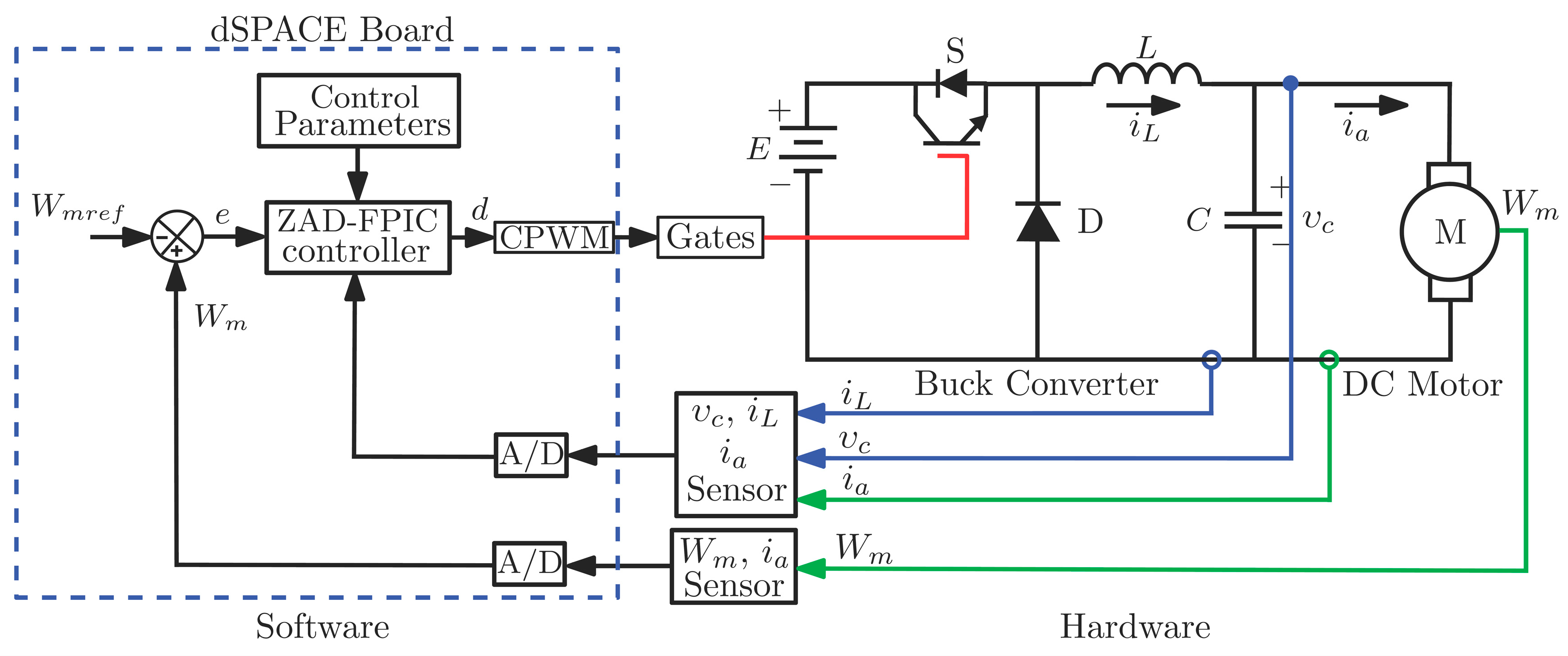
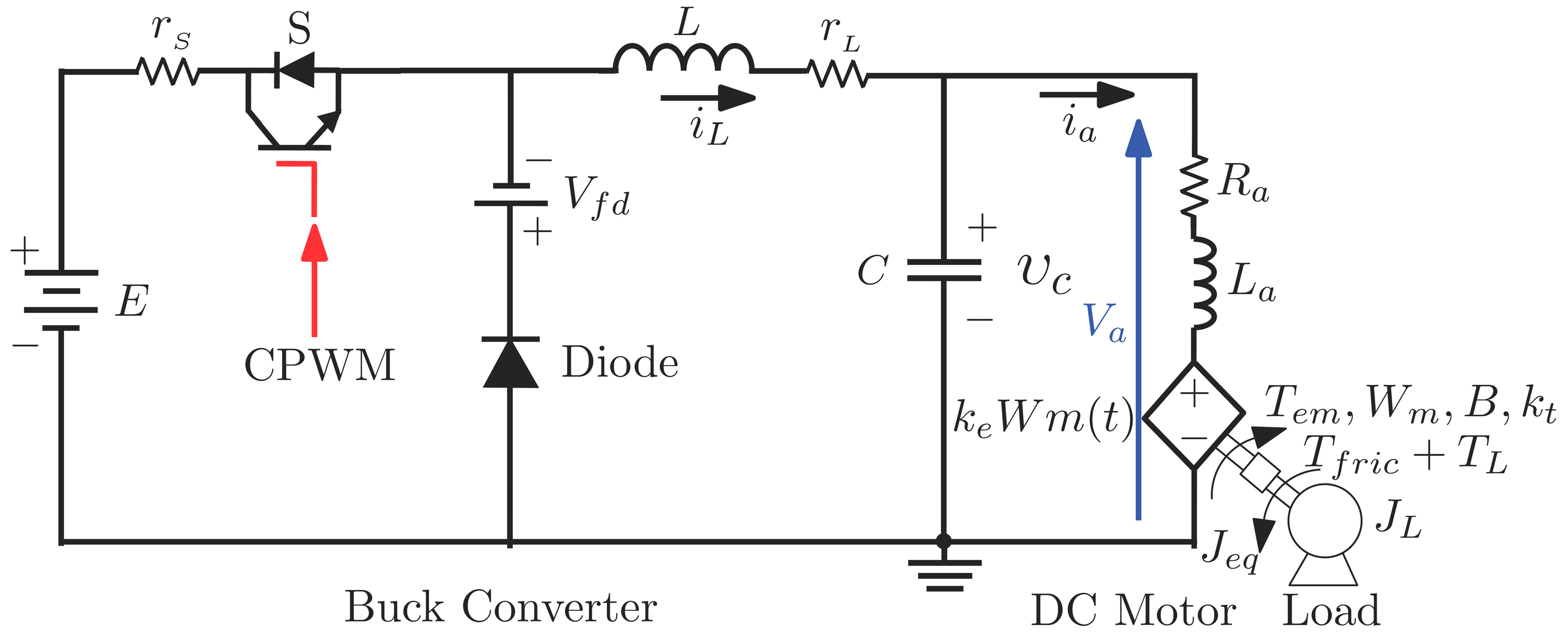
2.1. Model of the Buck Converter with a DC Motor

The DC motor and mechanical load are modeled by Equations (1) and (2), which correspond to the electromechanical part of the system, described by a second order mathematical model, where the state variables are the speed of the DC motor ( W m ) in rad/s and the armature current ( i a ) in amps.
W ˙ m ( t ) = B W m ( t ) J e q + k t i a ( t ) J e q + T f r i c J e q + T L J e q
i a ( t ) = k e L a W m ( t ) + R a L a i a ( t ) + V a L a
The term k e is the voltage constant (V/rad/s) of the motor, L a is the armature inductance (mH), R a is the armature resistance ( Ω ), V a is the voltage applied to the motor (V) and is equal to υ c , B is the viscous friction coefficient (N·m/(rad/s)), J e q is the moment of inertia (kg·m2), k t is the motor torque constant (N·m/A), T f r i c is the friction torque (N·m), and T L is the load torque (N·m).
Figure 2 shows that the complementary part of the electrical subsystem corresponds to the circuit of the buck converter. The mechanical subsystem corresponds to the rotating mechanical part of the motor and the mechanical load connected to it. Here, the way in which the output of the buck converter feeds the DC motor with a regulated voltage is illustrated. The presented configuration allows the speed of the motor to be controlled in a closed loop, manipulating the state of the switch ( S = ON and S = OFF ); that is, the control gate of MOSFET transistor.
The state variables of the buck converter with the motor depends on the state of the switch (S). Thus, if the switch is closed ( S = ON ) and the diode is not conducting (inactive), the system is represented as described in Equation (3).
[ W ˙ m i a υ c ˙ i L ˙ ] = [ B J e q k t J e q 0 0 k e L a R a L a 1 L a 0 0 1 C 0 1 C 0 0 1 L ( r L + r s ) L ] [ W m i a υ c i L ] + [ ( T f r i c + T L ) J e q 0 0 E L ]
In a compact form, it can be represented as shown in Equation (4), where x 1 = W m , x 2 = i a , x 3 = υ c , and x 4 = i L .
x ˙ = A 1 x + B 1
When the switch is open ( S = OFF ) and the diode is conducting, the model is described as presented in Equation (5).
[ W ˙ m i a υ c ˙ i L ˙ ] = [ B J e q k t J e q 0 0 k e L a R a L a 1 L a 0 0 1 C 0 1 C 0 0 1 L r L L ] [ W m i a υ c i L ] + [ ( T f r i c + T L ) J e q 0 0 V f d L ]
This last equation can be written in compact form as shown in Equation (6).
x ˙ = A 2 x + B 2
The system described above by Equations (3) and (5) is of the fourth order. Parameters C and L are the capacitance and the inductance of the power converter, respectively. The total resistance at the source ( r s ) is equal to the sum of the internal resistance of the source ( r s s ) and the resistance of the MOSFET ( r M ), as presented in Equation (7). The total resistance in the inductor ( r L ) is equal to the sum of the resistance in the coil ( r L L ) and the resistance used to measure the current in the inductor ( r M e d ), as presented in Equation (8).
r s = r s s + r M
r L = r L L + r M e d
The term V f d is the forward voltage and E is the power supply voltage, corresponding to the value that feeds the buck converter and the DC motor when the state of switch S is active. Note when S is inactive - V f d is fed to buck converter. Considering that the CPWM signal is configured with a pulse in the center and the buck converter works in continuous conduction mode, the dynamics of the system over a full period are described by the Equation (9).
x ˙ = { A 1 x + B 1 s i k T t k T + d T / 2 A 2 x + B 2 s i k T + d T / 2 < t < k T + T d T / 2 A 1 x + B 1 s i k T + T d T / 2 < t < k T + T

2.2. Speed Control of a DC Motor

As a speed control is applied to the DC motor W m , the reference speed W m r e f must be followed in the rotary load. Thus, in the sampling period k T , the tracking error is defined in Equation (10):
e ( k T ) = W m ( k T ) W m r e f ( k T )
Furthermore, by considering that the system is of fourth order, the sliding surface s ( x ) [29] describes the third order dynamic behavior of the error ( e ( k T ) ), given by Equation (11):
s ( k T ) = e ( k T ) + k s 1 d e ( k T ) d ( k T ) + k s 2 d 2 e ( k T ) d ( k T ) 2 + k s 3 d 3 e ( k T ) d ( k T ) 3
The coefficients k s 1 , k s 2 ,   and   k s 3 are parameterized as a function of the constant of the inductive-capacitive (LC) filter multiplied by the factors K S 1 , K S 2 ,   and   K S 3 , as shown in Equation (12). The factors K S 1 , K S 2 ,   and   K S 3 are the parameters of the ZAD controller and can be adjusted to impose a desired dynamic in the closed loop system. Note that, such parameters can be considered to construct dimensional bifurcation diagrams.
k s 1 = K S 1 L C k s 2 = K S 2 L C k s 3 = K S 3 L C L C
When the reference signal W m r e f is constant, Equation (11) can be written as shown in Equation (13), and the derivate is equal to Equation (14):
s ( k T ) = W m ( k T ) W m r e f ( k T ) + k s 1 d W m ( k T ) d ( k T ) + k s 2 d 2 W m ( k T ) d ( k T ) 2 + k s 3 d 3 W m ( k T ) d ( k T ) 3
s ˙ ( k T ) = d W m ( k T ) d ( k T ) + k s 1 d 2 W m ( k T ) d ( k T ) 2 + k s 2 d 3 W m ( k T ) d ( k T ) 3 + k s 3 d 4 W m ( k T ) d ( k T ) 4
The duty cycle can be calculated as expressed in Equation (15):
d k ( k T ) = 2 s ( k T ) + T s ˙ ( k T ) T ( s ˙ ( k T ) s ˙ + ( k T ) )
where s ( k T ) is calculated with Equation (11) at the beginning of each switching period for the system given in Equation (3). Thus, s ( k T ) = s ( k T ) |   S = O N ; s ˙ + ( k T ) is calculated with Equation (12) for the system given in Equation (3); that is, s ˙ + ( k T ) = s ˙ ( k T ) |   S = O N . Additionally, the parameter s ˙ ( k T ) is calculated with Equation (14) for the system given by Equation (5); that is, s ˙ ( k T ) = s ˙ ( k T ) |   S = O F F .
Given the period of delay in the control action, the new duty cycle is calculated, as in Equation (16).
d k ( k T ) = 2 s ( ( k 1 ) T ) + T s ˙ ( ( k 1 ) T ) T ( s ˙ ( ( k 1 ) T ) s ˙ + ( ( k 1 ) T ) )
By considering the ZAD-FPIC technique, the new duty cycle is calculated to ensure that the load and the motor rotate at the desired speed ( W m r e f ), leading to the expression for the duty cycle given in Equation (17).
d Z A D F P I C ( k T ) = d k ( k T ) + N d * N + 1
Combining Equations (16) and (17), the following control law of the ZAD-FPIC is obtained, as shown in Equation (18):
d Z A D F P I C ( k T ) = ( 2 s ( ( k 1 ) T ) + T s ˙ ( ( k 1 ) T ) T ( s ˙ ( ( k 1 ) T ) s ˙ + ( ( k 1 ) T ) ) + N d * ) ( N + 1 ) 1
where d * is calculated at the beginning of each period, as shown in Equation (19):
d * = d k ( k T ) |   e s t a d o   e s t a b l e
Finally, a saturation function must be applied to consider the actual physical limits of the duty cycle between 0 and 1, leading to the saturation function described in Equation (20):
d = { d Z A D F P I C ( k T )   if   0 < d Z A D F P I C ( k T ) < 1 1 if 1 d Z A D F P I C ( k T ) 0 if d Z A D F P I C ( k T ) 0

3. Results and Analysis

This section shows the numerical and experimental results for the speed control of a DC motor using a buck converter controlled with the ZAD-FPIC technique. The results are divided into results obtained for the transient and steady states.

3.1. Transient-State Results

The results were obtained according to the quantization effects, defined as: W m = 28 bits, ADC 12 bits ( i a ,   υ c ,   i L ) , and d 10 bits, with K S 1 = 2 ,   K S 2 = 2 , K S 3 = 30 , and N = 1 , leading to a delay of one period.
Figure 3a shows the speed of the motor for the simulation test (black), the speed of the motor for the experimental test (blue), and the reference speed ( W m r e f ). Initially, it starts from a reference speed ( W m r e f = 100   rad / s ). Then, at t = 1 s the reference signal changes ( W m r e f = 400   rad / s ) and Figure 3c shows the numerical error (black) and the experimental error (blue) of the DC motor speed signals ( W m ). Considering the overshoot (OS), the settling time (ST), and the steady-state error (SSError) as performance indices of the control technique, Figure 3a shows the OS, with a value of 0.57% for the simulation test and a 0% for the experimental test, while the SSError are -0.1645% and 0.4245% for the simulation and experimental results, respectively. Additionally, the experimental results in Figure 3a confirm the predictions obtained by the numerical simulations. Considering the settling time for the controlled variable W m , the numerical simulation produces a value of ST = 0.1473 s, while the experimental value is of ST = 0.1859 s, as shown in Table 2.
Figure 3b shows the motor supply voltage ( V a = υ c ) for the simulation (black) and experimental (blue) tests, with very similar behavior shown for both the steady- and transient-state stability, although with a slight difference in time delay for the transient state. It is important to note that the supply voltage of the DC motor does not exceed 36 volts and that this has a low ripple during the steady state, which is optimal for the proper functioning of the DC motor and for maintaining the speed ( W m ) with low steady-state error. Figure 3d confirms that the duty cycle ( d ) is not saturated during the steady state, which would generate a CPWM signal with fixed switching frequency.
In Figure 3, there are some small differences between the results obtained with the simulation and the experiment, especially in the transient state. The experiment shows a longer setup time and less overshoot, because in the simulation test the parasitic resistor of the capacitor in the buck converter was not considered. Additionally, in the steady state there are also small differences between the simulation and experimental results, because the resistance used to measure the current in the inductor ( r M e d ) increases when the temperature of the shunt resistor r M e d increases.

3.2. Steady-State Results

Here, this manuscript presents the results for the steady-state operation of the buck converter with a DC motor that is controlled by the ZAD-FPIC technique are presented. The goal of this analysis is to present the dynamic behavior of the closed loop system when the control parameter K S 3 changes. An additional purpose is to define a tuning criteria for control parameters, while evaluating the dynamic characteristics of the system stability via bifurcations diagrams. The control parameter K S 3 defined in Equation (10) was selected as the bifurcation parameter because this parameter is more sensible than the two others control parameters ( K S 1 and K S 2 ).
Figure 4 and Figure 5 show numerical and experimental results of the duty cycle and the motor speed with respect to the control parameter K S 3 , respectively. Three different quantization levels were considered for the variables as follows. Firstly, W m with 28 bits; i a , υ c , and i L , each with 12 bits; and a duty cycle of 10 bits. Secondly, W m with 26 bits; i a , υ c , and i L , each with 10 bits; and a duty cycle of 8 bits. Thirdly, W m with 24 bits; i a , υ c , and i L , each with 8 bits; and a duty cycle of 6 bits.
In the experimental test, the steady-state error is higher when the resistance r M e d increases, for which the bifurcation diagrams presented in Figure 4 show a slight difference between the simulation and experimental results. To improve this difference, it is recommended to perform a better calibration of the parasitic resistance, along with real-time sensing of the resistances r M e d , r L , and r s . Thus, a greater correlation between the simulation and experimental results can be found.
In general, Figure 4 and Figure 5 show a good correlation between numerical and experimental results. Figure 4a shows that for the highest quantization levels, the stability limit at the numerical test has a value close to K S 3 = 22 a, while for the experimental test (Figure 4b) this value is K S 3 = 12 . For the lowest quantization level, the numerical test (Figure 4e) shows that the stability limit is close to K S 3 = 270 , while for the experimental test (Figure 4f) it is K S 3 = 170 . Therefore, from these results we can conclude that the experimental test presents a more stable behavior for lower values of K S 3 , and that as the quantization levels are reduced for both the simulation and experimental tests, the stability is lost and it is necessary to increase the value of K S 3 to obtain stability in the controlled signal W m .
Figure 5 shows that there is no clear stability limit, however by means of the duty cycle d it can be measured when the stability is lost. Both numerical and experimental tests showed that the system begins to be more unstable and that the bifurcation point moves to the right because of resolution lost in the measured variables. For all quantization levels, the responses of the controller were good and the regulation was performed to the desired reference point. However, some small differences between the experimental and simulated results were found during the tests for all cases.

4. Conclusions

This paper presented a speed control for a DC motor performed with the ZAD-FPIC technique. The results showed that the buck converter with the motor controlled by the ZAD-FPIC technique achieved good speed regulation, imposing the desired rotation value by means of the reference signal. Additionally, the bifurcation diagrams showed that the ZAD-FPIC technique allowed the closed-loop control of the speed in an electric motor, using a buck converter as an electric actuator. This can generate a speed regulation error of less than 3% for the entire range of variation of K S 3 , with K S 1 = K S 2 = 2, a delay period, and N = 1. The numerical and experimental tests showed that even with low quantization levels in the measured variables and in the PWM signal, the buck converter with the motor controlled by the ZAD-FPIC technique had good speed regulation. Finally, for the higher quantization limits, the system obtained low values for overshoot (OS), settling time (ST), and steady-state error (SSError).

Author Contributions

F.E.H., conceptualization, formal analysis, investigation, validation. J.E.C.-B., investigation, project administration, methodology, software; and C.I.H.V. conceived control application, data analysis, manuscript writing, review and editing. All authors have read and agreed to the published version of the manuscript.

Funding

This work was supported by Universidad Nacional de Colombia in Medellín under projects HERMES-34671 and HERMES-36911.

Acknowledgments

The authors thank to the School of Physics and the Department of Electrical Engineering and Automation for their valuable support to conduct this research. C.I.H.V. contributed to this paper being a research fellow at IM-CNR, of Naples, Italy.

Conflicts of Interest

The authors declare no conflict of interest.

Abbreviations

ADCAnalog-to-digital converter
ACAlternating current
CPWMCentered pulse width modulation
DCDirect current
DPWMDigital pulse width modulation
DSPDigital signal processor
FPGAField-programmable gate array
FPICFixed point induction control
LCInductive-capacitive
MOSFETMetal–oxide–semiconductor field-effect transistor
OSOvershoot
PIDProportional integral derivative
PWMPulse-width modulation
SISOSingle-input and single-output
SMCSliding mode control
SSErrorSteady-state error
STSettling time
SVPWMSpace vector pulse width modulation
ZADZero average dynamics
ZAD-FPICZero average dynamics and fixed point induction control

References

  1. Cuong, N.D.; Van Lanh, N.; Dinh, G.T. An Adaptive LQG Combined With the MRAS—Based LFFC for Motion Control Systems. J. Autom. Control Eng. 2015, 3, 130–136. [Google Scholar] [CrossRef]
  2. Sankardoss, V.; Geethanjali, P. PMDC Motor Parameter Estimation Using Bio-Inspired Optimization Algorithms. IEEE Access 2017, 5, 11244–11254. [Google Scholar] [CrossRef]
  3. Guerrero, E.; Linares, J.; Guzman, E.; Sira, H.; Guerrero, G.; Martinez, A. DC Motor Speed Control through Parallel DC/DC Buck Converters. IEEE Lat. Am. Trans. 2017, 15, 819–826. [Google Scholar] [CrossRef]
  4. Hoyos Velasco, F.; Candelo-Becerra, J.; Rincón Santamaría, A. Dynamic Analysis of a Permanent Magnet DC Motor Using a Buck Converter Controlled by ZAD-FPIC. Energies 2018, 11, 3388. [Google Scholar] [CrossRef] [Green Version]
  5. Jia, N.; Wang, T. Chaos control and hybrid projective synchronization for a class of new chaotic systems. Comput. Math. Appl. 2011, 62, 4783–4795. [Google Scholar] [CrossRef] [Green Version]
  6. Hoyos Velasco, F.E.; Toro-García, N.; Garcés Gómez, Y.A. Adaptive Control for Buck Power Converter Using Fixed Point Inducting Control and Zero Average Dynamics Strategies. Int. J. Bifurc. Chaos 2015, 25, 1550049. [Google Scholar] [CrossRef]
  7. Lascu, C.; Trzynadlowski, A.M. Combining the Principles of Sliding Mode, Direct Torque Control, and Space-Vector Modulation in a High-Performance Sensorless AC Drive. IEEE Trans. Ind. Appl. 2004, 40, 170–177. [Google Scholar] [CrossRef]
  8. Lascu, C.; Boldea, I.; Blaabjerg, F. Direct Torque Control of Sensorless Induction Motor Drives: A Sliding-Mode Approach. IEEE Trans. Ind. Appl. 2004, 40, 582–590. [Google Scholar] [CrossRef]
  9. Orlowska-Kowalska, T.; Dybkowski, M.; Szabat, K. Adaptive Sliding-Mode Neuro-Fuzzy Control of the Two-Mass Induction Motor Drive Without Mechanical Sensors. IEEE Trans. Ind. Electron. 2010, 57, 553–564. [Google Scholar] [CrossRef]
  10. Wu, J.; Pu, D.; Ding, H. Adaptive robust motion control of SISO nonlinear systems with implementation on linear motors. Mechatronics 2007, 17, 263–270. [Google Scholar] [CrossRef]
  11. Huang, A.-C.; Kuo, Y.-S. Sliding control of non-linear systems containing time-varying uncertainties with unknown bounds. Int. J. Control 2001, 74, 252–264. [Google Scholar] [CrossRef]
  12. Yazdanpanah, R.; Soltani, J.; Arab Markadeh, G.R. Nonlinear torque and stator flux controller for induction motor drive based on adaptive input–output feedback linearization and sliding mode control. Energy Convers. Manag. 2008, 49, 541–550. [Google Scholar] [CrossRef]
  13. Leva, A.; Piroddi, L.; Di Felice, M.; Boer, A.; Paganini, R. Adaptive relay-based control of household freezers with on–off actuators. Control Eng. Pract. 2010, 18, 94–102. [Google Scholar] [CrossRef]
  14. Di Felice, M.; Piroddi, L.; Leva, A.; Boer, A. Adaptive temperature control of a household refrigerator. In Proceedings of the 2009 American Control Conference, St. Louis, MO, USA, 10–12 June 2009; pp. 889–894. [Google Scholar]
  15. Hilairet, M.; Auger, F. Speed sensorless control of a DC-motor via adaptive filters. IET Electr. Power Appl. 2007, 1, 601. [Google Scholar] [CrossRef]
  16. Hu, H.; Yousefzadeh, V.; Maksimovic, D. Nonuniform A/D Quantization for Improved Dynamic Responses of Digitally Controlled DC-DC Converters. IEEE Trans. Power Electron. 2008, 23, 1998–2005. [Google Scholar] [CrossRef]
  17. Fung, C.W.; Liu, C.P.; Pong, M.H. A Diagrammatic Approach to Search for Minimum Sampling Frequency and Quantization Resolution for Digital Control of Power Converters. In Proceedings of the 2007 IEEE Power Electronics Specialists Conference, Orlando, FL, USA, 17–21 June 2007; pp. 826–832. [Google Scholar]
  18. Taborda, J.A.; Angulo, F.; Olivar, G. Estimation of parameters in Buck converter with Digital-PWM control based on ZAD strategy. In Proceedings of the 2011 IEEE Second Latin American Symposium on Circuits and Systems (LASCAS), Bogata, Colombia, 23–25 February 2011; pp. 1–4. [Google Scholar]
  19. Maksimovic, Z. Erickson Impact of digital control in power electronics. In Proceedings of the 16th International Symposium on Power Semiconductor Devices & IC’s, Kitakyushu, Japan, 24–27 May 2004; pp. 13–22. [Google Scholar]
  20. Peterchev, A.V.; Sanders, S.R. Quantization resolution and limit cycling in digitally controlled PWM converters. IEEE Trans. Power Electron. 2003, 18, 301–308. [Google Scholar] [CrossRef] [Green Version]
  21. Peng, H.; Maksimovic, D.; Prodic, A.; Alarcon, E. Modeling of quantization effects in digitally controlled DC-DC converters. IEEE 2004, 4312–4318. [Google Scholar] [CrossRef]
  22. Angulo, F.; Hoyos, F.; Olivar, G. Experimental results on the quantization in the ADC device for a ZAD-strategy controlled DC-DC buck converter. In Proceedings of the 7th European Nonlinear Dynamics Conference, Rome, Italy, 24–29 July 2011; pp. 1–6. [Google Scholar]
  23. Tirandaz, H.; Ahmadnia, M.; Tavakoli, H. Adaptive Projective Lag Synchronization of T and Lu Chaotic Systems. Int. J. Electr. Comput. Eng. 2017, 7, 3446–3453. [Google Scholar] [CrossRef] [Green Version]
  24. Corradini, L.; Mattavelli, P. Analysis of Multiple Sampling Technique for Digitally Controlled dc-dc Converters. In Proceedings of the 37th IEEE Power Electronics Specialists Conference, Jeju, Korea, 18–22 June 2006; pp. 1–6. [Google Scholar]
  25. Hoyos, F.E.; Burbano, D.; Angulo, F.; Olivar, G.; Toro, N.; Taborda, J.A. Effects of Quantization, Delay and Internal Resistances in Digitally ZAD-Controlled Buck Converter. Int. J. Bifurc. Chaos 2012, 22, 1250245. [Google Scholar] [CrossRef]
  26. Hoyos, F.E.; Rincón, A.; Taborda, J.A.; Toro, N.; Angulo, F. Adaptive Quasi-Sliding Mode Control for Permanent Magnet DC Motor. Math. Probl. Eng. 2013, 2013, 1–12. [Google Scholar] [CrossRef] [Green Version]
  27. Hoyos, F.E.; Candelo-Becerra, J.E.; Toro, N. Numerical and experimental validation with bifurcation diagrams for a controlled DC–DC converter with quasi-sliding control. TecnoLógicas 2018, 21, 147–167. [Google Scholar] [CrossRef] [Green Version]
  28. Fossas, E.; Griño, R.; Biel, D. Quasi-Sliding control based on pulse width modulation, zero averaged dynamics and the L2 norm. In Proceedings of the Advances in Variable Structure Systems—6th IEEE International Workshop on Variable Structure Systems, Orlando, FL, USA, 4–7 December 2001; pp. 335–344. [Google Scholar]
  29. Biel, D.; Fossas, E.; Ramos, R.; Sudria, A. Programmable logic device applied to the quasi-sliding control implementation based on zero averaged dynamics. In Proceedings of the Proceedings of the 40th IEEE Conference on Decision and Control (Cat. No.01CH37228), Orlando, FL, USA, 4–7 December 2001; Volume 2, pp. 1825–1830. [Google Scholar]
  30. Ramos, R.R.; Biel, D.; Fossas, E.; Guinjoan, F. A fixed-frequency quasi-sliding control algorithm: Application to power inverters design by means of FPGA implementation. IEEE Trans. Power Electron. 2003, 18, 344–355. [Google Scholar] [CrossRef]
  31. Angulo, F.; Olivar, G.; Taborda, J.; Hoyos, F. Nonsmooth dynamics and FPIC chaos control in a DC-DC ZAD-strategy power converter. In Proceedings of the ENOC, Saint Petersburg, Rusia, 30 June–4 July 2008; pp. 1–6. [Google Scholar]
  32. Hoyos, F.E.; Candelo, J.E.; Taborda, J.A. Selection and validation of mathematical models of power converters using rapid modeling and control prototyping methods. Int. J. Electr. Comput. Eng. 2018, 8, 1551. [Google Scholar] [CrossRef]
  33. Hoyos, F.E.; Candelo-Becerra, J.E.; Hoyos Velasco, C.I. Model-Based Quasi-Sliding Mode Control with Loss Estimation Applied to DC–DC Power Converters. Electronics 2019, 8, 1086. [Google Scholar] [CrossRef] [Green Version]
  34. Hernandez Marquez, E.; Silva Ortigoza, R.; Garcia Sanchez, J.R.; Garcia Rodriguez, V.H.; Alba Juarez, J.N. A New “DC/DC Buck-Boost Converter-DC Motor” System: Modeling and Experimental Validation. IEEE Lat. Am. Trans. 2017, 15, 2043–2049. [Google Scholar] [CrossRef]
  35. Silva Ortigoza, R.; Alba Juarez, J.N.; Garcia Sanchez, J.R.; Hernandez Guzman, V.M.; Sosa Cervantes, C.Y.; Taud, H. A Sensorless Passivity-Based Control for the DC/DC Buck Converter-Inverter-DC Motor System. IEEE Lat. Am. Trans. 2016, 14, 4227–4234. [Google Scholar] [CrossRef]
  36. Department of Electrical and Computer Engineering University of Minnesota. DSP Based Electric Drives Laboratory: User Manual; Department of Electrical and Computer Engineering University of Minnesota: Minneapolis, MN, USA, 2012.
Figure 1. Diagram of the buck converter with zero average dynamics and fixed point induction control (ZAD-FPIC) techniques to control the speed of a direct current (DC) motor. CPWM, centered pulse width modulation.
Applsci 10 01807 g001
Figure 2. Electromechanical system for speed control of a DC motor powered by a buck converter.
Applsci 10 01807 g002
Figure 3. Numerical and experimental behavior when there is a change in the speed reference signal ( W m r e f ): (a) motor speed signals ( W m ); (b) motor supply voltage ( V a = υ c ) ; (c) speed error; and (d) duty cycle.
Applsci 10 01807 g003
Figure 4. Numerical and experimental bifurcation diagrams for the duty cycle d with respect to the control parameter K S 3 . These diagrams are plotted considering the following quantization levels: (a) W m with 28 bits, analog–digital (ADC) inputs with 12 bits, d with 10 bits; (b) W m with 28 bits, ADC with 12 bits, and d with 10 bits; (c) W m with 26 bits, ADC with 10 bits, and d with 8 bits; (d) W m with 26 bits, ADC with 10 bits, and d with 8 bits; (e) W m with 24 bits, ADC with 8 bits, and d with 6 bits; and (f) W m with 24 bits, ADC with 8 bits, and d with 6 bits.
Applsci 10 01807 g004
Figure 5. Numerical and experimental bifurcation diagrams for the speed of the motor W m versus the control parameter K S 3 . These diagrams are plotted considering the following quantization levels: (a) W m with 28 bits, ADC with 12 bits, and d with 10 bits; (b) W m with 28 bits, ADC with 12 bits, and d with 10 bits; (c) W m with 26 bits, ADC with 10 bits, and d with 8 bits; (d) W m with 26 bits, ADC with 10 bits, and d with 8 bits; (e) W m with 24 bits, ADC with 8 bits, and d with 6 bits; and (f) W m with 24 bits, ADC with 8 bits, and d with 6 bits.
Applsci 10 01807 g005aApplsci 10 01807 g005b
Table 1. Parameters of the controller and the circuit.
ParameterDescriptionValue
r s Total resistance at the source 0.84   Ω
E Power supply voltage40.086 V
V f d Forward voltage 1.1 V
L Inductance 2.473 mH
r L Total resistance in the inductor 1.695   Ω
C Capacitance 46.27   μ F
R a Armature resistance 2.7289   Ω
L a Armature inductance 1.17 mH
B Viscosity friction coefficient0.000138 (N·m/(rad/s))
J e q Inertia moment 0.000115 (kg · m 2 )
k t Motor torque constant0.0663 (N·m/A)
k e Motor voltage constant 0.0663 (V/rad/s)
T f r i c Friction constant 0.0284 (N·m)
T L Load torque Variable (N·m)
W m r e f Speed referenceVariable (rad/s)
W m Speed of the DC motorVariable (rad/s)
N Control parameter of the FPIC 1
F c Switching frequency6 kHz
F s Sampling frequency6 kHz
1 T _ p Delay period 166.6   μ s
K S 1 Control parameter 2
K S 2 Control parameter2
K S 3 Control parameterVariable
Table 2. Performance of the closed loop system: overshoot (OS), settling time (ST), and steady-state error (SSError).
Index Simulation TestExperimental Test
OS (%)0.570
ST (seg)0.14730.1859
SSError (%)−0.16450.4245

