Featured Application
The study shown in this manuscript helps to guide the further application of a wall-climbing robot for the shipbuilding industry.
Abstract
The shipbuilding industry is very important for many countries. As an essential process in the shipbuilding industry, surface preparation (or coating removal) is gaining more and more attention. The traditional process used for ship hull coating removal is a sand-blasting process, which is harmful to the environment and inefficient. Recently, high pressure water jet technology has been developed to replace the traditional sand-blasting process. However, there are still many technical problems to be solved. In this paper, one wall-climbing robot was developed to remove coating based on high pressure water jet technology. Coating removal experiments under various experimental conditions were carried out and the corresponding coating removal rate for each case was obtained and compared. In addition, numerical simulation based on Fluid software was conducted to observe the water jet process more visually. Results show that the processing parameters, including the water pressure, travelling speed, inclined angle, and stand-off distance, can greatly influence the coating removal effect. The optimal processing parameters are obtained to guide the application of the high pressure water jet technology based on the designed wall-climbing robot for the shipbuilding industry.
1. Introduction
The shipbuilding industry is one of the supporting industries in many countries. The ship surface needs to be painted for protection. Before painting, the ship should be cleaned to make the surface be qualified to achieve the desired effect. A after a long time travelling in the river or the ocean, the ship hull surface will inevitably be covered with different coatings, which could greatly influence the travelling speed and performance of the ship. So, the ship surface should also be cleaned regularly. Surface cleaning (or coating removal) is an essential process prior to coating in the shipbuilding industry to maintain a smooth surface, minimize the fuel consumption, and extend the life span of the constructed ship [1].
Many cleaning methods have been proposed and applied for hull cleaning in the last several decades. The most widely used traditional ship surface cleaning method is called sand-blasting [2], which generates a profile in micrometer-range by accelerating a sand-basting media through a nozzle with compressed air. However, this sand-blasting method has an obvious disadvantage: the concentration of soluble substances on the treated surface after sand-blasting is very high, and thus an extra cleaning process should be added before recoating [3]. Besides the sand-blasting method, there are also other surface preparation methods, such as high temperature oxidation [4], electrochemical method [5] and laser coating removal method [6]. The former two methods are not environmental friendly, and they both require large energy consumption, while the latter can induce thermal and physical damage to the work-piece due to excessive heat produced by the laser. Recently, hybrid laser-water-jet technology was proposed to yield high material removal rate without thermal damage [7], the energy consumption was also reduced but the costs of applying the two technologies are quite expensive.
According to the literature mentioned above, the challenges faced during ship hull cleaning can be addressed as: How to minimize the energy consumption? How to realize environmental protection? How to enhance the cleaning efficiency? For the first two requirements, high speed water jet technology has been introduced recently as a promising substitute method [8]. During the water jet process, the potential energy of the high pressure water is transferred to the kinetic energy of the jet and the water jet with high velocity striking on the target can produce strong force to impact on the materials. Compared with the traditional methods, the water jet process is quite environmentally friendly, cost effective, and without abrasive contamination or heat effect zone. In the last few decades, water-jet technology has been widely used for cutting, drilling, milling [8], forming [9,10], coating removal, and comminution [11], etc.
With the aim of coating removal application, extensive analyses of the water jet technology have been presented based on experiments. For example, Momber et al. [3] experimentally investigated the surface quality features of one hot-rolled low-carbon steel (UH1) after high speed water jet. The roughness, hardness, and surface wettability can be increased significantly by high speed water jet profiling. Huang et al. [12] adopted water jet technology to remove the heat-formed coating for Titanium alloy Ti-Al-4V. Results validated that compressive residual stress can be induced to the treated surface during the water jet process, which is beneficial to prevent stress corrosion cracking and fatigue fracturing. Even though we can visually observe the coating removal effect through experiments, the change of the high pressure water parameters, including water pressure, jet velocity, and stress distribution, during the water jet process is still a black box for us.
In order to understand the water jet mechanism for coating removal in a more comprehensive way, corresponding theoretical study and numerical simulation are essential. So far, many scholars have conducted such researches. For example, Xie and Rittel [13] established one simplified 2D theoretical model and finite element model to predict the metallic surface roughness resulting from the water jet peening. The velocity distribution and pressure distribution in the water jet area can be roughly obtained. However, the simplified 2D model has limitation in predicting the actual surface roughness on a solid metallic surface. Recently, Mabrouki and Raissi [14,15] adopted a numerical modelling based on Arbitrary Lagrangian-Eulerian (ALE) formulation to analyze the interactional physics between a moving water jet and a coated target. The erosion phenomenon can be visually observed, which helps to understand the material removal mode. However, the ALE formulation is relatively expensive. In order to reduce the computational time, Ma et al. (2008) [16] presented a numerical method by means of the hybrid code of Smooth Particle hydrodynamics (SPH) and FEA to predict the water jet penetration process. The relationship between the jet velocity and the erosion capacity is obtained based on the simulation results. It should be noted more corresponding water jet experiments should be added to validate the numerical simulation results.
In the last few decades, the climbing robotic system, which can adhesive to the metal surface, were widely studied to realize the automation and high efficiency. The commonly used adhesion methods for climbing robots in the literature include vacuum adhesion [17], bio-inspired adhesion [18], gripping to the surface method [19], magnetic adhesion [20,21], and so on. Each method has its advantages and disadvantages, and detailed analysis can be found in the literature [22]. Generally speaking, the magnetic adhesion method is more suitable for the climbing robot carrying coating removal instruments in the ship-building industry [23] due to its reliable adhesion, low cost, and low energy. Recently, combining the high pressure water jet technology and mechanical automation, one permanent magnetic tracked wall-climbing robot has been developed to realize the coating removal for big ships. In this paper, the influence of some processing parameters, such as water pressure, stand-off distance and travelling speed, on the actual coating removal effect is systematically investigated through experiments and numerical simulation. The rest of the paper is organized as follows. The structure of the wall-climbing robot is shortly introduced in Section 2. The experimental results and the numerical simulation results are presented in Section 3. The analysis in detail is discussed in Section 4. Finally, Section 5 contains the conclusions.
2. Wall-Climbing Robot Introduction for Coating Removal
2.1. Structure Design of Wall-Climbing Robot
The wall-climbing robot equipped with the coating removal device contacts with the ship surface and carries out coating removal jobs. So, it should have large capacity, high wall motion stability, good wall adaptability, good motion flexibility, and guarantee the removal of coating on the surface of the ship at the same time. Through our long-time attempts, one novel wall-climbing robot is designed and fabricated as shown in Figure 1. It is composed of a magnetic walking system, a drive system, a cleaning system, an auxiliary system and a robot frame. Figure 2 shows the matching devices for offering the high-pressure water jet, including high pressure pump, vacuum pump, and air compressor. The pump is capable of developing a water pressure up to 300 MPa. It should be noted that, the magnetic force of the robot is designed much larger than the reaction force of the water pressure. So there is no need to worry about the falling down of the robots during the coating removal process [24]. In our previous research, the performance of the wall-climbing robot with coating removal device was tested, the derusting grade can reach to “Sa 2.5” and the derusting efficiency can reach to 45 m2/h, so the performance of the designed device meets the requirements of ship derusting.
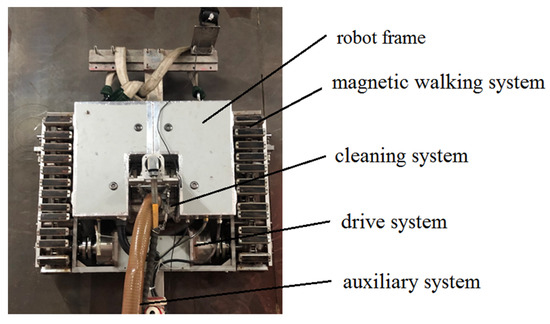
Figure 1.
Structure of the wall-climbing robot.
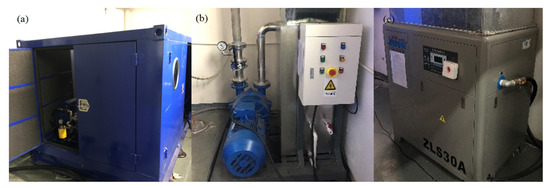
Figure 2.
Experimental device for offering high pressure water jet (a) high pressure pump; (b) vacuum pump; (c) air compressor.
2.2. Internal Structure of the Coating Removal Device
In our previous work [20,24], the design ideas, including the magnetic force and the structure of the robot, are analyzed in detail. In this paper, what we care most about is the structure of the coating removal system. The internal structure is shown in Figure 3. As can be seen from the figure, the coating removal device includes rotating shaft high-pressure water pipe, nozzles, rotating joint, and sealing brush. In order to improve the coating removal effect, 8 nozzles are designed and fabricated. The coating removal device makes contact with the high pressure pump set system, vacuum recovery system, and crawling system.
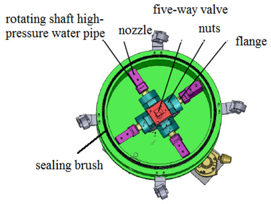
Figure 3.
Internal structure of the coating removal device.
During the coating removal process, high-pressure water is induced from the high-pressure pump set system and transferred to the rotating shaft high-pressure water pipe through a high-pressure pipe. Then, the high-pressure water impacts on the coated surface through the specific nozzles. During the whole coating removal process, the coting removal device and the vacuum recovery system are connected through the vacuum pipe. The vacuum recovery system, which can produce strong vacuum flow, increases the vacuum degree in the coating removal device. Thereby, the coating and waste water can be recovered.
3. High Pressure Water Jet Experiments and Numerical Simulation
3.1. High Pressure Water Jet Experimental Procedure
The basic water jet diffusion theory under high pressure was first put forward by Leu et al. [25] as shown in Figure 4. It can be seen there are mainly three stages along the water jet direction: initial stage (stage 1), basic stage (stage 2) and dissipated stage (stage 3). The water jet velocity inside the potential core of stage 1 is always equal to the nozzle exit velocity, so the energy in stage 1 is huge and thus stage 1 is typically used for cutting or stripping. In stage 2, the velocity of the water jet near the centerline declines linearly and thus the energy is lower than stage 1. Stage 2 is mainly used for coating removal, optimization of coating adherence and creating rough surface for a dental implant [26]. However, for stage 3, the water jet is dissipated too much, so stage 3 is not feasible as the energy of the water jet in this stage cannot be used efficiency. For our study, Stage 2 is the objective one and the proper stand-off distance should be adopted.
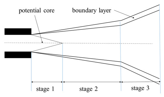
Figure 4.
Schematic diagram of high pressure water jet diffusion.
In order to investigate the influence of processing parameters on the coating removal effect on the metal surface, several high pressure water jet experiments were carried out in this section. All the experiments were carried out using the robot system shown in Figure 1. For this study, the influence of water pressure, travelling speed, and stand-off distance on the coating removal rate were experimentally studied. Each investigated parameter was assigned four levels. For each case, the same travelling path was applied to provide consistent conditions for three times and a 100 × 300 mm area was selectively removed.
Figure 5 shows the experimental condition. The travelling platform for the wall-climbed robot is one large magnetic Q235 steel wall with thickness of 15 mm. The surface of the magnetic steel wall is covered with a paint of coat, which is hard to remove manually. The surface quality after high pressure water jet is measured by a small instrument called a coating thickness gauge as shown in Figure 6. The gauge can be used to measure the thickness of the residual coating on the metal wall quickly, accurately, and conveniently. For each case, at least 50 positions were measured and the average value was used to describe the thickness of the residual coating. The coating removed rate can be obtained by the following equation.
where h is the residual coating thickness and hinitial is the initial coating thickness. The larger the value of w, the better the coating removal effect.
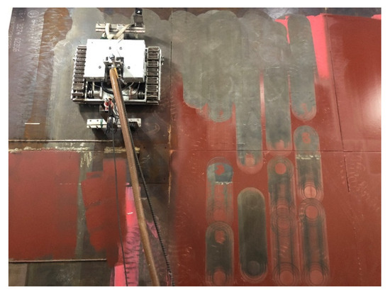
Figure 5.
High pressure water jet experimental platform.
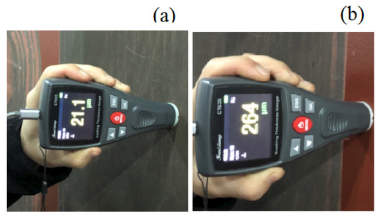
Figure 6.
Coating thickness gauge (a) measurement of the residual coating thickness; (b) measurement of the initial coating thickness.
3.2. High Pressure Water Jet Numerical Simulation
From the high pressure water jet experiments we can only observe the final coating removal effect while the pressure and speed distribution of water during the jet process is hard to observe visually. In order to investigate and analyze the change of water flow in a more efficient way, the numerical simulation method based on the general fluid simulation software FLUENT is used in this section.
It should be noted that there are 8 nozzles with the same diameters for the experimental coating removal device. To simplify the finite element simulation, only 1 nozzle is analyzed, so the equivalent diameter used in the finite element simulation can be calculated as follows,
The diameter for each nozzle is 0.3 mm, so the equivalent diameter for the nozzle used in FEM is about 1 mm.
In order to save the calculation time, the 2D finite element model is used. The diameter, length-diameter aspect and shrinking angle are 1 mm, 3, and 13o, respectively. The flow field model is a cylinder with diameter of 80 mm and height of 15 mm or larger, depending on the stand-off distance. To obtain accurate simulation results, it is necessary to define the proper physical model, materials and the corresponding boundary conditions. For this study, the VOF model is chosen as the multiphase model, where the first phase is air and the second phase is water. The realizable k-epsilon model is chosen as the turbulent model. The pressure-inlet is chosen for the inlet boundary condition and a standard atmosphere is chosen as the outlet boundary condition. The whole simulation process is that high pressure water forms into high speed jet through the nozzle, and impacts the target surface through air to induce impact. Here, the rigid wall means the ship-hull surface with coating. For the case with the stand-off distance of 30 mm and the inclined angle of 0°, the number of the mesh for the fluid field is 23,690. Figure 7 shows the finite element model and the corresponding boundary conditions for the case with the stand-off distance of 30 mm and the inclined angle of 0°.
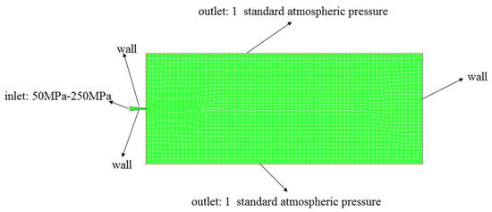
Figure 7.
Finite element model for high pressure water jet process.
It should also be noted that, considering the existing experimental condition, the inclined angle is not easy to change, so the influence of the inclined angle on the coating removal effect is analyzed only based on numerical simulation.
4. Results and Discussion
4.1. Influence of Water Pressure on the Coating Removal for the Metal Wall
High pressure water has the power to remove coating using the wall-climbing robot. In this section, the influence of water pressure on the coating removal effect was investigated. Four levels of high pressure (100, 120, 140, and 160 MPa) were chosen and compared. Figure 8 shows the surface condition for the four levels with the other experimental conditions as follows: the stand-off distance is 15 mm, the travelling speed is 2.25 m/min and the inclined angle is 10 degree. It can be found that the coating removal effect is greatly influenced by the applied water pressure. When the water pressure is 100 MPa, there is still much residual coating on the metal surface, while when the water pressure is larger than 120 MPa, most of the coating can be removed quite well. After the experiments, the coating thickness gauge was used to measure the thickness of the residual coating. Figure 9 shows the measured removal rate for the four cases. So, considering both the coating removal efficiency and the coating removal rate, the optimal impacting water pressure is 120 MPa.
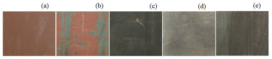
Figure 8.
Surface condition under various water pressure levels (a) initial state; (b) 100 MPa; (c) 120 MPa; (d)140 MPa; (e)160 MPa.
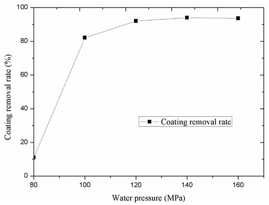
Figure 9.
Coating removal rate for various water pressure levels.
In order to investigate the influence of water pressure on the target surface’s impact effect more clearly, the numerical simulation under various water pressures was carried out. To better understand the influence of water pressure on the target surface, the water pressure in a more wide range is investigated. For this study, the stand-off distance and the inclined angle used in the simulation is 30 mm and 0°, respectively. Meanhile, the impacting water pressures are 100, 150, 200, and 250 MPa. Figure 10 shows the predicted velocity distribution under various water pressure. It can be seen that the maximum velocity always occurs at the outlet of the nozzle. The slight velocity divergence near the nozzle outlet is due to the consideration of surface tension. When the high pressure water impacts the wall surface, the velocity in the center is reduced to 0 quickly while the velocity on both sides remains very huge, as shown in Figure 10.
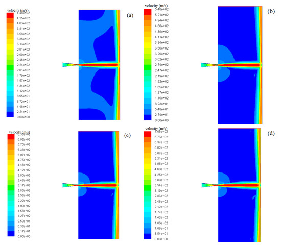
Figure 10.
Predicted velocity cloud chart under various inlet water pressures (a) 100 MPa; (b) 150 MPa; (c) 200 MPa; (d) 250 MPa.
According to Bernoulli’s law, the theoretical water jet exit velocity can be calculated as follows:
where P is the inlet pressure of the nozzle, is the water density, and the parameter is a nozzle efficiency parameter, which was taken as =0.95 for this study. So, for the operating pressure used in this study, the corresponding jet velocity can be obtained from the equation.
Figure 11 shows the predicted outlet velocity of the nozzle under various water pressures. The predicted value coincides well with that of the theoretical calculation value based on Equation (3). The maximum error between the predicted value and the theoretical value is less than 0.5%, so the reliability of the numerical simulation results is validated.
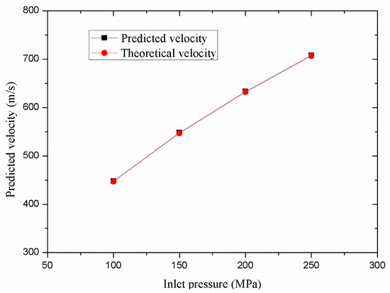
Figure 11.
Comparison of the outlet velocity of the nozzle between theoretical result and numerical one.
The predicted static pressure distribution and shear stress distribution along the target surface under various water pressures are also obtained and the case with water pressure of 100 MPa is shown in Figure 12. It can be seen that for the specific numerical condition, the maximum static pressure reacting on the target surface is at the center of the jet. With the increase of the distance from the jet center, the static pressure gradually decreases. However, the shear stress at the center of the jet is almost 0. With the increase of the distance from the jet center, the shear stress gradually increases. Actually the shear stress distribution corresponds with the velocity distribution shown in Figure 10. In addition, Figure 13 also shows that the maximum static pressure and the maximum shear stress increase with the increased water pressure. So, increasing the water pressure can significantly improve the water jet impacting effect. Here, it should also be noted that, compared with the static pressure shown in Figure 12 and Figure 13, the shear stress along the rigid wall is quite small, so the shear stress is not discussed for Section 4.2 and Section 4.4.
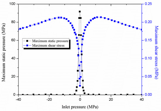
Figure 12.
Predicted static pressure and shear stress distribution along the target surface under inlet pressure of 100 MPa.
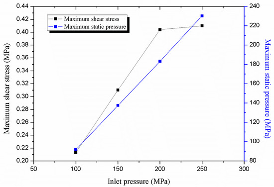
Figure 13.
Influence of water pressure on the maximum static pressure and the maximum shear stress on the target surface.
4.2. Influence of Stand-Off Distance on the Coating Removal for the Metal Wall
The stand-off distance means the distance between the outlet of the nozzle and the target surface. Here in this section, the coating removal experiments under four levels of stand-off distances (10, 15, 20, and 25 mm) are carried out and compared. Figure 14 shows the surface condition for the four cases with the other experimental condition as follows: the water pressure is 120 MPa, the travelling speed is 2.25 m/min and the inclined angle is 10 degree. It can be seen, for the case with stand-off distance is 25 mm, there are still obvious residual coating. Figure 15 also shows the measured coating removal rate for the four cases. It is clear that the coating removal rate decreases with the increased stand-off distance. That’s because the water pressure gradually disputes during the water jet process as shown in Figure 4. When the stand-off distance is larger, the residual water pressure impacting on the target surface is lower.
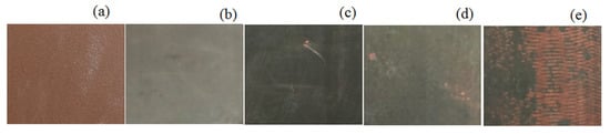
Figure 14.
Surface condition under various stand-off distances (a) initial state; (b) 10 mm; (c) 15 mm; (d) 20 mm; (e)25 mm.
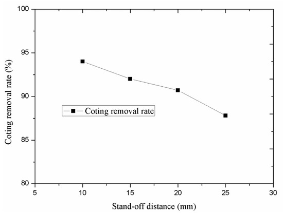
Figure 15.
Coating removal rate for various stand-off distances.
The numerical simulation calculation under various stand-off distances in a wide range (15, 30, 45, and 60 mm) were also conducted. For this study, the inlet water pressure and the inclined angle are 200 MPa and 0°, respectively. As can be seen from Figure 16, the velocity reacting on the target surface decreases with the increased stand-off distance. In addition, the water flow becomes more divergent with the increased stand-off distance. Figure 17 also shows the predicted maximum static pressure reacting on the target surface. With the increase of the stand-off distance, the static pressure deceases. This can be explained as follows. When the high-pressure water jet is ejected from the nozzle outlet, it sucks in the surrounding air and energy loss increases with the increased stand-off distance, resulting in the decrease of the static pressure. So, considering the results shown in both Figure 16 and Figure 17, it can be concluded that decreasing the stand-off distance can obviously improve the jet impacting effect. For this study, considering the actual experimental results, the optimal stand-off distance is 15 m/min.
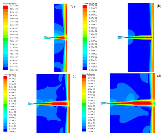
Figure 16.
Predicted velocity cloud chart under various stand-off distances (a) 15 mm; (b) 30 mm; (c) 45 mm; (d) 60 mm.
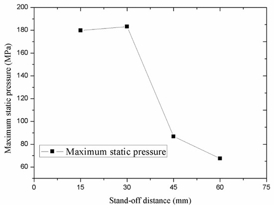
Figure 17.
Influence of stand-off distance of nozzle on the static pressure on the impacting surface.
4.3. Influence of Travelling Speed on the Coating Removal for the Metal Wall
The travelling speed of the wall-climbing robot can significantly influence the coating removal efficiency. However, if the wall-climbing robot runs too fast, the coating removal rate may be not so satisfactory. So, it is necessary to quantitatively investigate the relationship between the travelling speed and the coating removal rate. In this section, four levels of travelling speeds (1.5, 2.25, 3, and 3.75 m/min) were chosen and compared based on the water jet experiments. Figure 18 shows the surface condition for the four levels with the other experimental condition as follows: the water pressure is 120 MPa, the stand-off distance is 15 mm and the inclined angle is 10 degree. When the travelling speed is lower, the surface condition is cleaner. Figure 19 also shows the measured coating removal rate for the four cases. Results show that the removal rate of the coating increases with the decreased travelling speed. However, it should be noted that lower travelling speed means lower cleaning efficiency as shown in Table 1. So, considering both the efficiency and coating removal rate, the proper travelling speed for this study should be 2.25 m/min.
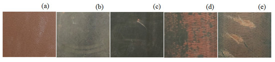
Figure 18.
Surface condition under various travelling speeds (a) initial state; (b) 1.5 m/min; (c) 2.25 m/min; (d) 3 m/min; (e) 3.75 m/min.
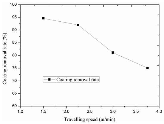
Figure 19.
Coating removal rate for the three pressure levels.

Table 1.
Relationship between travelling speed and cleaning efficiency.
4.4. Influence of Inclined Angle of the Nozzle on the Coating Removal for the Metal Wall
For the designed wall-climbing robot, the rotary movement of the coating removal device is driven by the shear force induced by the water pressure impacting on the target surface. So the water jet direction cannot be completely perpendicular to the target surface. Here, the angle α between the water jet direction and the normal direction of the target surface is called inclined angle. If α is smaller, most of the water pressure is reacting on the normal direction of the target surface and thus the impacting force is larger while the shear force is lower. If the shear force is too small, the coating removal device may not rotate at all and thus the gap between each experimental nozzle cannot be cleaned as expected. However, if α is too big, the normal force reacting on the surface may not large enough and much energy could be lost. So, the real reaction effect of the inclined angle on the coating removal results should be investigated. Considering the limitation of the existing experimental conditions, the numerical simulations under various inclined angles (0°, 10°, 20° and 30°) were analyzed.
For this study, the inlet water pressure and the stand-off distance are 200 MPa and 30 mm, respectively. Figure 20 shows the predicted velocity cloud chart under various inclined angles. It can be seen that the interaction between water and air are more complicated with larger inclined angles. The predicted maximum static pressures reacting on the target surface under various inclined angles are also obtained as shown in Figure 21. Results show that when the inclined angle is larger, the maximum static pressure is decreased. When the inclined angle is 30°, the working efficiency of the high pressure water is only 19.5%, so if the maximum static pressure is too small, the water jet energy can be greatly lost. Considering both the working efficiency and the rotation movement, the proper inclined angle should be chosen.
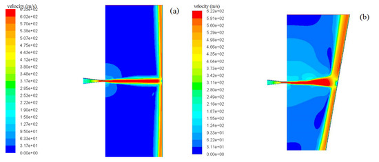
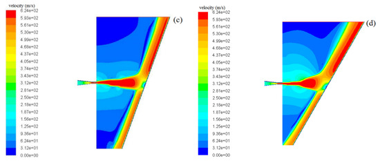
Figure 20.
Predicted velocity cloud chart under various inclined angles (a) 0°; (b) 10°; (c) 20°; (d) 30°.
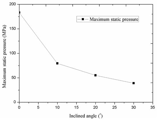
Figure 21.
Influence of inclined angle on the static pressure on the target surface.
5. Conclusions
Surface preparation (or coating removal) is an essential process for shipbuilding and many other industries. One permanent-magnetic wall-climbing robot with a coating removal device was developed to remove the coating on the ship-hull surface. In this paper, the basic structure of the wall-climbing robot and the corresponding coating removal device are introduced. Then, the coating removal experiments under various processing parameters for high pressure water jet technology, including the water pressure, the travelling speed, and the stand-off distance, were carried out based on the designed wall-climbing robot. Numerical simulations of the high pressure water jet process under various processing parameters based on one nozzle with the equivalent diameter were conducted to better observe the whole high-pressure water jet process. The key conclusions can be summarized as follows:
- (1)
- The water jet numerical simulation based on the general fluid dynamic numerical simulation software FLUENT is validated by the theoretical calculation.
- (2)
- The coating removal rate can be greatly improved by increased water pressure and decreased stand-off distance. The optimal water pressure and stand-off distance for this experimental study is 120 MPa and 15 mm, respectively.
- (3)
- Travelling speed can influence both the coating removal rate and efficiency. The optimal travelling speed for this experimental study is 2.25 m/min.
- (4)
- For this designed wall-climbing robot, the rotatory movement of the coating removal device is driven by the shear force, so the proper inclined angle, that can keep enough impact force and rotation force, should be chosen.
Author Contributions
F.Z. and K.H. contributed to the main idea of this paper; X.S. and Z.L. prepared the experimental platform; F.Z. performed the experiments, analyzed the data and wrote the paper. K.H. is the project principal investigator; Y.W. conducted the corresponding numerical simulation; I.M. gave some data analysis and revision suggestions. All authors have read and agreed to the published version of the manuscript.
Funding
This research was funded by Guangdong Science and Technology Planning Project, grant number 2017B090914004 and Guangdong Basic and Applied Basic Research Foundation, grant number 2019A1515012035.
Acknowledgments
The authors would like to thank Yiu Lian Dockyards (Shekou) Limited for providing the experimental platform.
Conflicts of Interest
The authors declare no conflict of interest.
References
- Ortiz, F.; Pastor, J.A.; Alvarez, B.; Iborra, A.; Ortega, N.; Rodriguez, D.; Conesa, C. Robots for hull ship cleaning. In Proceedings of the 2007 IEEE International Symposium on Industrial Electronics, Vigo, Spain, 4–7 June 2017; pp. 2077–2082. [Google Scholar]
- Lee, D.; Ku, N.; Kim, T.W.; Lee, K.Y.; Kim, J.; Kim, S. Self-travelling robotic system for autonomous abrasive blast cleaning in double-hulled structures of ships. Automat. Constr. 2010, 19, 1076–1086. [Google Scholar] [CrossRef]
- Momber, A.W.; Wong, Y.C.; Budidharma, E.; Tjo, R. Surface profiling of low-carbon steel with supersonic waterjets. Wear 2002, 249, 853–859. [Google Scholar] [CrossRef]
- Lu, D.P.; Yin, H.; Tan, D.Q. A Method for Removing the Surface Coating of Cemented Carbide. Chinese Patent 102,392,249 A, 28 November 2011. [Google Scholar]
- Cristobal, A.; Conde, A.; Housden, J. Electrochemical stripping of hard ceramic chromium nitride coatings. Thin. Solid. Films. 2005, 484, 238–244. [Google Scholar] [CrossRef][Green Version]
- Marimuthu, S.; Kamara, A.M.; Whiteheat, D.; Mativenga, P.; Li, L. Laser removal of tin coatings from WC micro-tools and in-progress monitoring. Opt. Laser. Technol. 2010, 42, 1233–1239. [Google Scholar] [CrossRef]
- Yun, H.; Zou, B.; Wang, J.; Huang, C.Z.; Li, S.Z. Optimization of energy consumption in coating removal for recycling scrap coated cemented carbide tools using hybrid laser-waterjet. J. Clean. Prod. 2019, 229, 104–114. [Google Scholar] [CrossRef]
- Folks, J. Waterjet- An innovative tool for manufacturing. J. Mater. Process. Technol. 2009, 209, 6181–6189. [Google Scholar] [CrossRef]
- Shi, Y.; Zhang, W.Z.; Cao, J.; Ehmann, K.F. Experimental study of water jet incremental micro-forming with supporting dies. J. Mater. Process. Technol. 2019, 268, 117–131. [Google Scholar] [CrossRef]
- Wei, S.G.; Xu, L.P.; He, K.; Li, J.H.; Feng, W.; Du, R.X. Experimental study on manufacturing metal bellows forming by water jet incremental forming. Int. J. Adv. Manuf. Technol. 2015, 81, 129–133. [Google Scholar] [CrossRef]
- Xue, Y.Z.; Si, H.; Xu, S.Y.; Yang, Z.L. Experiments on the microscopic damage of coal induced by pure water jets and abrasive water jets. Powder. Technol. 2018, 332, 139–149. [Google Scholar] [CrossRef]
- Huang, L.; Kinnell, P.; Shipway, P.H. Removal of heat-formed coating from a titanium alloy using high pressure waterjet: Influence of machining parameters on surface texture and residual stress. J. Mater. Process. Technol. 2015, 223, 129–138. [Google Scholar] [CrossRef]
- Xie, J.; Rittel, D. A two-dimensional model for metallic surface roughness resulting from pure waterjet peening. Int. J. Eng. Sci. 2017, 120, 189–198. [Google Scholar] [CrossRef]
- Mabrouki, T.; Raissi, K. Stripping process modelling: Interaction between a moving waterjet and coated target. Int. J. Mach. Tool. Manu. 2002, 42, 1247–1258. [Google Scholar] [CrossRef]
- Mabrouki, T.; Raissi, K.; Cornier, A. Numerical simulation and experimental study of the interaction between a pure high-velocity waterjet and targets: Contribution to investigate the decoating process. Wear 2000, 239, 260–273. [Google Scholar] [CrossRef]
- Ma, L.; Bao, R.H.; Guo, Y.M. Waterjet penetration simulation by hybrid code of SPH and FEA. Int. J. Impact. Eng. 2008, 35, 1035–1042. [Google Scholar] [CrossRef]
- Yoshida, Y.; Ma, S. Design of a wall-climbing robot with passive suction cups. In Proceedings of the 2010 IEEE International Conference on Robotics and Biomimetics, Tianjin, China, 14–18 December 2010; pp. 1513–1518. [Google Scholar]
- Balaguer, C.; Gimenez, A.; Jardon, A. Climbing robots’ mobility for inspection and maintenance of 3D complex environments. Auton. Robot. 2005, 18, 157–169. [Google Scholar] [CrossRef]
- Boscariol, P.; Henrey, M.A.; Li, Y.; Menon, C. Optimal gait for bioinspired climbing robots using dry adhesion: A quasi-static investigation. J. Bionic. Eng. 2013, 10, 1–11. [Google Scholar] [CrossRef]
- Cai, J.N.; He, K.; Fang, H.T.; Chen, H.; Hu, S.J.; Zhou, W. The design of permanent-magnetic wheeled wall-climbing robot. In Proceedings of the 2017 IEEE International Conference on Information and Automation (ICIA), Macau, China, 18–20 July 2017. [Google Scholar]
- Chen, X.L.; Wu, Y.P.; Hao, H.D.; Shi, H.L.; Huang, H.C. Tracked wall-climbing robot for calibration of large vertical metal tanks. Appl. Sci. 2019, 9, 2671. [Google Scholar] [CrossRef]
- Seriani, S.; Scalera, L.; Caruso, M.; Gasparetto, A.; Gallina, P. Upside-Down Robots: Modeling and experimental validation of magnetic-adhesion mobile systems. Robotics 2019, 8, 41. [Google Scholar] [CrossRef]
- Milella, A.; Maglietta, R.; Caccia, M.; Bruzzone, G. Robotic inspection of ship hull surfaces using a magnetic crawler and monocular camera. Sens. Rev. 2017, 37, 425–435. [Google Scholar] [CrossRef]
- Hu, S.J.; Peng, R.S.; He, K.; Li, J.H.; Cai, J.N.; Zhou, W. Structure design and magnetic force analysis of a new crawler-type permanent magnetic adsorption wall-climbing. In Proceedings of the 2017 IEEE International Conference on Information and Automation (ICIA), Macau, China, 18–20 July 2017. [Google Scholar]
- Leu, M.C.; Meng, P. Mathematical modelling and experimental verification of stationary water jet cleaning process. J. Manuf. Sci. Eng. 1988, 120, 571–579. [Google Scholar] [CrossRef]
- De Bruyn, H.; Christiaens, V.; Doornewaard, R.; Jacobsson, M.; Cosyn, J.; Vervaeke, S. Impact surface roughness and patient factors on long-term peri-implant bone loss. Periodontology 2000, 73, 218–227. [Google Scholar] [CrossRef] [PubMed]


© 2020 by the authors. Licensee MDPI, Basel, Switzerland. This article is an open access article distributed under the terms and conditions of the Creative Commons Attribution (CC BY) license (http://creativecommons.org/licenses/by/4.0/).