Featured Application
Battery management system design on lead-acid batteries with electrochemical impedance spectroscopy and first principle linear circuit model.
Abstract
Both the frequency domain Nyquist curve of electrochemical impedance spectroscopy (EIS) and time domain simulation of DC equivalent first principle linear circuit (FPLCDCequ) are some of the fundamentals of lead-acid batteries management system design. The Nyquist curve is used to evaluate batteries’ state of health (SoH), but the curve does not distinguish charging/discharging impedances on electrode–electrolyte interfaces in the frequency domain. FPLCDCequ is used to simulate batteries’ terminal electrical variables, and the circuit distinguishes charging/discharging impedances on electrode–electrolyte interfaces in the time domain. Therefore, there is no direct physical relationship between Nyquist and FPLCDCequ This paper proposes an AC equivalent first principle linear circuit (FPLCACequ) by average switch modeling, and the novel circuit distinguishes charging/discharging impedances on electrode–electrolyte interfaces in Nyquist. The novel circuit establishes a physical bridge between Nyquist and FPLCDCequ for lead-acid batteries management system design.
1. Introduction
Lead-acid batteries are widely used as a backup in power systems, e.g., in telecommunication stations and power plants. On lead-acid batteries, both the frequency domain Nyquist curve of EIS [1] and time domain simulation of DC equivalent first principle linear circuit (FPLCDCequ) [2] are widely used in battery management system (BMS) design. In BMS design, linear electrical circuits, including AC and DC equivalent circuits, are more competitive than nonlinear electrochemical circuits. Firstly, linear electrical circuits, with electrical equivalent lumped elements, are intuitive for electrical engineers to understand the physical and electrochemical characteristics of batteries [3]. Batteries’ physical and electrochemical parameters are mapped to electrical lumped elements, which are used to estimate batteries’ state of health (SoH) or state of charge (SoC) [4]. Secondly, linear impedances are more convenient for simulating batteries’ terminal electrical variables in software. Advanced digital signal processing requires that elements should be linear functions of frequency [5], and electrical lumped impedances are nature linear functions of frequency. However, lumped electrochemical impedances are nonlinear functions of frequency [6], and are not convenient for programming. Unless special mention is given, the following circuits in this paper only refer to linear electrical circuits.
Elements in a circuit, fitting for EIS, are simplified from governing equations [7,8] in lead-acid battery and have clear physical/electrochemical meanings; so, they are the first principle and basis of classic threshold-based BMS design. Charge-transfer resistance and double-layer capacitance are related to non-cohesion of active mass of electrodes; contacting resistances represent the existence of stratification and corrosion of electrodes; nonlinear diffusion impedances characterize sulfating of electrodes [4,9]. Multi-scale SoC/SoH judgment based on EIS is an extension of threshold-based management [10,11]; circuits elements are nonlinearly influenced by various factors, e.g., SoC, charging or discharging, superimposed DC current [12]; other form signals, such as short step response, can take place of sinusoidal excitation to demonstrate dominant aging mechanisms on battery capacity [8]. The leading edge of BMS to forecast and optimize batteries’ SoC/SoH is usually based on time domain simulation [13,14]; therefore, extracting directional DC charge-transfer resistances from an AC Nyquist curve is significant in time domain research on BMS.
The Nyquist curve, describing AC steady-state volt-ampere characteristics of batteries, is used to evaluate SoH [1], and AC equivalent behavioral linear circuit (BHLCACequ) is used for the curve fitting [15]. In certain frequency bands of Nyquist, impedances on electrode–electrolyte interfaces dominate curve shape [1,3]; at a certain frequency point of Nyquist, BHLCACequ has a corresponding time domain waveform to approach the measurement point. Then, the behavioral relationship between BHLCACequ and Nyquist is established.
BHLCACequ is an interpretation basis of the Nyquist curve [16]. The physical and electrochemical meanings of contacting resistor (), stray inductor () and electrolyte bulk capacitor () in BHLCACequ are relatively clear [3]. Individual elements in BHLCACequ rely on the first principle [17], simplified from governing equations [7,8], but the elements’ combination does not consider the first principle. Linear impedance on positive (or negative) electrode–electrolyte interfaces is generally modeled by a charge-transfer resistor () and a double-layer capacitor () [3,18]. The describes the DC steady-state volt-ampere characteristics of an electrode–electrolyte interface according to Tafel law [19]; the describes the DC transient-state volt-ampere characteristics of an electrode–electrolyte interface according to spatial anisotropy [19]. Both and in BHLCACequ do not distinguish charging/discharging, too [15,18,20]. The impedance, on a single (positive or negative) electrode–electrolyte interface, consisting of one and one , characterizes both charging and discharging at the same time. The authors of [21] also suggest that the long-chain series of an circuit can approximate the Nyquist curve as close as possible, but long-chain series elements do not have practical physical and electrochemical meanings, and cannot distinguish charging/discharging impedances either.
FPLCDCequ, describing DC steady-state and transient-state volt-ampere characteristics of batteries, typically includes , , and impedances on electrode–electrolyte interfaces () [20]. distinguishes into charging ()/discharging () [2,20,22]. , , and in FPLCDCeq are a function of the surface area of the solid electrolyte [2,3,22]. Surface areas of charging and discharging for electrochemical processes are mutually exclusive and collectively exhaustive [2,3,22]. Generally, they are different; therefore, charging () and discharging () charge-transfer resistors are different. However, in FPLCDCequ does not distinguish charging/discharging [3,20], and only one capacitor ( or ) combines both charging and discharging DC transient-state volt-ampere characteristics of each electrode. is generated on a solid electrolyte interface and always in parallel with in FPLCDCequ [3,20]. Therefore, charging ( or ) and discharging ( or ) double-layer capacitors should depend on their individual electrochemical reaction surface areas, and they should be different in general.
Existing BHLCACequ does not distinguish charging impedances (, , and ) from discharging impedances (, , and ) on electrode–electrolyte interfaces. Therefore, there is no physical relationship between the EIS Nyquist curve and FPLCDCequ.
This paper proposes AC equivalent first principle linear circuit (FPLCACequ) by average switch modeling [23]. FPLCACequ accurately models the steady-state AC fundamental response as the same as FPLCDCequ, and average switch modeling calculates steady-state DC static response as the same as FPLCDCequ. FPLCACequ bridges the physical relationship between Nyquist and FPLCDCequ. FPLCACequ, focused on AC-input, is an extension of FPLCDCequ. These two first principle linear circuits complement each other to guide lead-acid BMS design.
2. AC Equivalent First Principle Linear Circuit and Experiments
2.1. Requirements of FPLCACequ
The FPLCACequ must meet three requirements: Firstly, elements in FPLCACequ should be AC equivalent linear, and voltage responses in circuit simulation should not contain a steady-state DC static component. Secondly, charging impedances (, , and ) and discharging impedances (, , and ) on electrode–electrolyte interfaces in FPLCACequ should be distinguished. Thirdly, steady-state AC fundamental responses in FPLCACequ should be consistent with steady-state AC fundamental responses in FPLCDCequ.
2.2. Analysis of AC Equivalent Impedances on Electrode–Electrolyte Interfaces by Average Switch Modeling
Directional linear impedances on electrode–electrolyte interfaces of FPLCDCequ are solid in theory [2,3], and its transient-state and steady-state responses under DC-input have also been experimentally verified [2,3]. Furthermore, in this paper, average switch modeling is proposed to explore responses of FPLCDCequ under pure AC-input and to analyze AC equivalent linear impedances on electrode–electrolyte interfaces.
2.2.1. Vector Analysis of Responses of Electrode–Electrolyte Interfaces by Average Switch Modeling
Assuming that amplitudes of sinusoidal currents excited from the electrochemical workstation are small enough, voltage responses of batteries’ terminals are also trigonometric waveforms as the same frequency as excitation currents [24]. At any certain frequency, internal impedances of batteries are equivalent to linear-constant-time-invariant impedances, and impedances on electrode–electrolyte interfaces of both positive and negative electrodes are also considered as linear-constant-time-invariant [1,3].
• Analysis of Steady-State DC Static Responses by Tafel law
Under stable AC current injection, steady-state DC static responses of impedances on electrode–electrolyte interfaces should be zero in EIS operation. If there are any steady-state DC static voltage responses of batteries’ terminals, there should exist non-zero steady-state DC static current injections through batteries’ terminals according to Tafel law [25]. This is contradictory to EIS practice.
• Vector Analysis of Steady-State AC Fundamental Voltage Response by average switch modeling
Firstly, linear decomposition of equivalent steady-state AC fundamental response vector on electrode–electrolyte interfaces exists. According to the electrical vector analysis principle [26], space vector is regarded as a static vector in rotating the coordinate as the same rotating frequency as stable excitation, and each space vector () has a clear amplitude and phase in the rotating coordinate. In the rotating coordinate, the target vector can be equivalent to two vectors ( and ) by linear superposition. As shown in Figure 1a, amplitudes and phases of the two vectors can be different, and there are infinite sets of two vectors ( and ) equivalent to the target space vector (). In the following sections, the target vector is set as steady-state AC fundamental voltage response of impedances on electrode–electrolyte interfaces of both positive and negative electrodes.
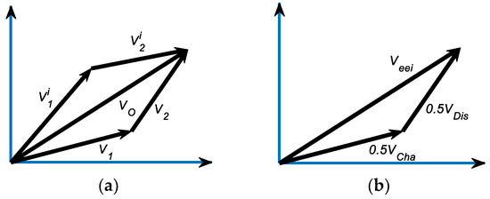
Figure 1.
Vector analysis of steady-state AC fundamental voltage responses: (a) there are infinite sets of two vectors ( and ) equivalent to target vector () in rotating coordinate; (b) the target vector () is equivalent to the sum of new charging () and discharging () vectors by linear superposition.
Secondly, the linear decomposition of steady-state AC fundamental voltage response vector on electrode–electrolyte interfaces is unique. When stable AC current injections flow through charging impedances on electrode–electrolyte interfaces of both positive and negative electrodes, the charging vector of steady-state the AC voltage fundamental response () is obtained as Equation (1), so be discharging vector of steady-state AC voltage fundamental responses (), as Equation (2). During one period of stable AC current injections, both charging and discharging vectors appear for exactly half a period, and their available time is mutually exclusive and collectively exhaustive. According to average switch modeling [23,26], a new charging vector (), as Equation (3), is exactly half an amplitude and the same phase of charging vector in the coordinate plane. So be new discharging vector (), as Equation (4) because, during stable AC excitation, both charging and discharging vectors are only available at a half-cycle of stable AC injection. The target vector () can only be formed by new charging () and discharging () vectors by linear superposition as Equation (5) and Figure 1b. Figure 2 is an AC equivalent impedance () similar to Equation (6) by removing the current () from Equation (5). The physical meanings of elements in the above equations are explained in Table A1 of the Appendix A.
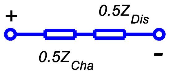
Figure 2.
AC equivalent first principle impedances () on electrode–electrolyte interfaces.
• Time Domain Simulation of FPLCACequ Impedances
During charging, the voltage response of impedances on electrode–electrolyte interfaces of both positive and negative electrodes is regarded as a linear transfer function [3,20], and positive half-wave sinusoidal current excites the transfer function in its charging half-cycle. So be during discharging. Two linear transfer functions responses are linearly superposed to simulate a one-cycle voltage response of impedances on electrode–electrolyte interfaces.
Vector analysis has a strict time-sharing requirement; the sinusoidal current excitation is naturally divided into positive and negative half. Amplitude superposition is carried out by linearly adding up charging and discharging voltage responses. Figure 3 is an FPLCDCequ [3,20] for steady-state simulation with divided half-wave sinusoidal currents, and is intuitive compared with Figure 2.

Figure 3.
DC equivalent first principle impedances on electrode–electrolyte interfaces.
However, in FPLCDCequ simulation, steady-state DC static voltage response of impedances on electrode–electrolyte interfaces appear in Figure 4. Under positive half-wave sinusoidal current injection, periodic voltage responses of charging impedances on electrode–electrolyte interfaces are excited; According to average switch modeling principles, an equivalent DC positive response is on electrode–electrolyte interfaces, as Equation (7). Similarly, an equivalent DC negative response is on electrode–electrolyte interfaces, as Equation (8). Then equivalent DC response on electrode–electrolyte interfaces is the sum of and , as Equation (9). Steady-state DC static voltage responses are shown in FPLCDCequ simulation under DC-input [2,3,20], but do not exist in experiments under AC-input. The physical meanings of elements in the above equations are explained in Table A1 of the Appendix A.
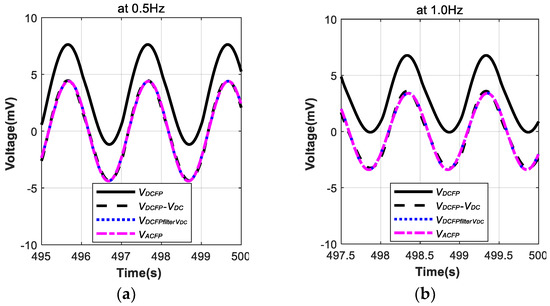
Figure 4.
Steady-state AC fundamental voltage responses of both DC equivalent first principle linear circuit (FPLCDCequ) and AC equivalent first principle linear circuit (FPLCACequ) are equal in simulations: (a) 5A rms current injections at 0.5 Hz; (b) 5A rms current injections at 1.0 Hz.
Linear superposition of terminal transient voltage responses in FPLCDCequ, excited by time-division input, has been verified on physical-electrochemical derivation, numerical calculations and experiments under DC-input [20]; linear sub-models are switched by a low-pass filter and hysteresis relay [20]. In Figure 4, the black solid line is the output of transient voltage responses in FPLCDCequ simulation under AC-input. The black dashed line cancels the steady-state DC voltage response from the black solid line, and the DC component is exactly equal to Equation (9). The blue dotted line filters the steady-state AC fundamental voltage response out of the black solid line by Equation (10), and the blue dotted line is very close to the black dashed line, which has a little distortion from higher harmonics. The pink dot-dash line is the steady-state AC voltage response in the FPLCACequ simulation. The physical meanings of elements in the above equations are explained in Table A1 of the Appendix A.
In Figure 4, the steady-state AC fundamental voltage response of both FPLCACequ and FPLCDCequ in the simulation are equal, and electrode–electrolyte interface impedances in FPLCACequ and FPLCDCequ are one-to-one equivalent. The equivalent relationship is unique, and equivalent results in vector analysis are available for both steady and transient states in electrical circuits [27]. The possibility of distinguishing charging/discharging impedances is lost in BHLCACequ because BHLCACequ obtains a steady-state AC fundamental voltage response by filtering out DC responses in FPLCDCequ as the blue dotted line. Therefore, the composition of steady-state AC fundamental voltage is not studied in BHLCACequ, but research on the composition of DC components is necessary to study FPLCDCequ and FPLCACequ.
2.2.2. AC Equivalent Frist Principle Impedances on Electrode–Electrolyte Interfaces
Equation (6) implies that equivalent AC impedances on electrode–electrolyte interfaces is equal to half of the sum of charging and discharging impedances on electrode–electrolyte interfaces of both positive and negative electrodes.
Each element in AC equivalent first principle impedances is non-directional and totally linear. This advantage simplifies the simulation, and it does not need to determine the direction of excitation in advance, nor does it need auxiliary circuits to switch sub-models in simulations [20]. Further, the charging impedances () are strictly separated from discharging impedances (). Equations (11) to (13) expand the impedances (, , ) to charge-transfer resistors (, , and ) and double-layer capacitors (, , and ); Equation (14) is an equivalent transformation for the Nyquist fitting. The physical meanings of elements in the above equations are explained in Table A1 of the Appendix A.
2.3. AC Equivalent First Principle Linear Elements on Batteries
, and are typical equivalent first principle linear elements on batteries [3,20]. Under AC current injections, steady-state DC static and AC fundamental voltage responses of each element are formulated in Equations (15)–(20). These equivalent elements only have AC fundamental voltage responses, and do not have DC static voltage responses; therefore, it is not necessary to determine the direction of excitation in advance, nor does it need to switch sub-models in simulations. The physical meanings of elements in the above equations are explained in Table A1 of the Appendix A.
Linear , replacing the nonlinear Warburg impedance () in Equation (21), represents the diffusion process of electrolyte. usually characterizes the diffusion process of electrolyte [19], so researchers [28] propose to connect with impedances on electrode–electrolyte interfaces in series to simplify the equivalent circuit. Warburg impedances of both negative and positive electrodes are combined as one equivalent . In this paper, this equivalent is replaced by one . Firstly, linear has a clear electrochemical meaning under small-signal EIS operation [20]; secondly, linear is a special nonlinear Constant Phase Element () with P equal to one in Equation (22).
2.4. Experiment of Steady-state DC static Voltage Responses on Battery Terminals
The purpose of the experiment is to clarify that there are no steady-state DC static voltage responses on batteries’ terminals under stable AC sinusoidal current excitation. Nowadays, board-level BMS is used to operate at frequencies as low as 0.5 Hz or 1.0 Hz. So, the electrochemical workstation (Solartron ModulabXM) sends high-precision pure trigonometric (sinusoidal) current-source excitations (5A rms) to the tested battery at two fixed frequencies, 0.5 Hz and 1.0 Hz. The tested battery, manufactured by Zhejiang Narada Power Source Co., Ltd., as shown in Figure 5, is a 500 Ah lead-acid cell with model name GFM-500R and number E-08#. The detection circuit, in Figure 6, is designed to sample battery terminal voltage and to amplify errors between terminal voltage and reference voltage (2.132 V) with DC gain (40.14). The overall configuration of the experimental platform is in Figure 7. AC current injections of the electrochemical workstation are intermittently closed and open, and the outputs of the detection circuit are measured by a digital multimeter (UNI-T UT33A+). When AC current injection is closed, the multimeter display is read at a fixed time delay; when AC current injection is open, the multimeter display is read at the same fixed time delay. After measuring two cycles by the same time delay, length of the next time delay is increased by 30 s.
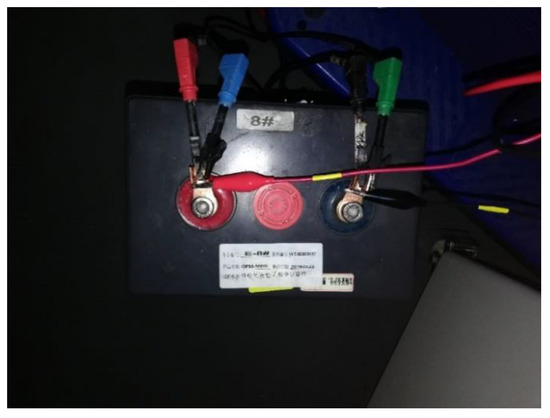
Figure 5.
Tested battery E-08#.

Figure 6.
Detection circuit of steady-state DC static over-potentials on batteries’ terminals.

Figure 7.
Experimental platform.
2.5. Experiment of Steady-State AC fundamental Voltage Responses on Battery Terminals
Voltage response in the frequency domain reflects the steady-state amplitude and phase electrical characteristic of batteries’ terminals. The experimental platform is set as Figure 7, but excludes the detection circuit.
2.6. Experiment of Extracting Directional Charge-Transfer Resistance in AC Nyquist Curve
Four batteries were paralleled in 70 °C accelerated aging tests for seven months, part of the twelve batteries stack multi-objective experiments in Figure 8. All batteries were designed and manufactured by Zhejiang Narada Power Source Co., Ltd. with model name GFM-500R; these four samples were numbered as E-52#, E-11#, E-02# and E-20#. After float charging with regulated terminal voltage (N*2.23 V, N is the number of testing batteries in the stack) at 70 °C for a month, the batteries stack was discharged for checking capacities and recharged for capacities recovering at room temperature. Twenty-four hours after recharging, each battery was individually scanned by the electrochemical workstation (Solartron ModulabXM) with 5A rms pure sinusoidal currents excitation and frequencies bands were from 1 MHz to 1 kHz. After EIS scanning, batteries were put back into a high-temperature container for the next test round. Battery capacities checking are plotted in Figure 9a and Nyquist curves of EIS are displayed in Figure 9b–e. Only even-numbered round experiments are shown to avoid crossing in Figure 9b–e.

Figure 8.
Twelve batteries stack.

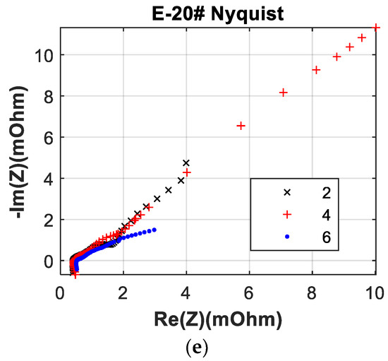
Figure 9.
Capacities and EIS plots of batteries in accelerated aging tests: (a) batteries’ capacities of tests rounds; (b) EIS of E-52#; (c) EIS of E-11#; (d) EIS of E-02#; (e) EIS of E-20#.
3. Results and Discussion
3.1. Results of Steady-State DC Static Voltage Responses on Battery Terminals
All measurement points are shown in Table 1. Some points data, before closed AC injection, are off records because they are almost the same as the last check point. The time domain outputs of the detection circuit are shown in Figure 10. Procedures of pulse and step were used to reduce sampling points and to act as low-pass filtering. In Figure 10, outputs are mainly in the transient process at the beginning, and gradually approaching to 660 mV after one hour. Then, the outputs are nearly stable around 660–670 mV, and the maximum voltage fluctuation, 10 mV in the secondary side, will not exceed 0.25 mV in the primary side, which is significantly less than the magnitude (3.2 mV in the primary side) obtained by FPLCDCequ simulation in Figure 4. Therefore, the experiment can prove that steady-state DC static overpotential on electrode–electrolyte interfaces is indeed zero under fixed frequency AC current inputs.

Table 1.
Measurement timings and results.
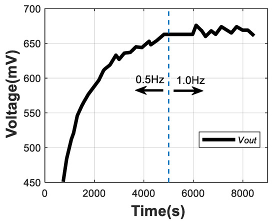
Figure 10.
Time series of outputs of detection circuit.
Under sinusoidal AC current injections, steady-state DC static voltage responses on electrode–electrolyte interfaces are nearly zero in this detection experiment. Results of the detection circuit are almost ideal; some small errors can be tolerated and may be caused by ambient temperature fluctuations and battery self-heating by injection currents. Maybe a little steady-state DC static voltage response does appear on battery terminals, although it does not affect FPLCACequ in engineering applications.
3.2. Results of Steady-State AC Fundamental Voltage Responses on Battery Terminals
Figure 11a is FPLCACequ on battery, and Figure 11b is BHLCACequ on battery. FPLCACequ is shown in Equation (23) and BHLCACequ is shown in Equation (24). The Nyquist curve from the EIS of the same 500 Ah battery (E-08#) is plotted with diagonal cross points in Figure 12. In Figure 12, the fitting curve of FPLCACequ is plotted with cross points, and the fitting curve of BHLCACequ is plotted with dot points. The physical meanings of elements in the above equations are explained in Table A1 of the Appendix A.
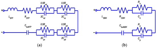
Figure 11.
Circuits fitting for EIS and Bode plots: (a) FPLCACequ; (b) behavioral linear circuit (BHLCACequ).
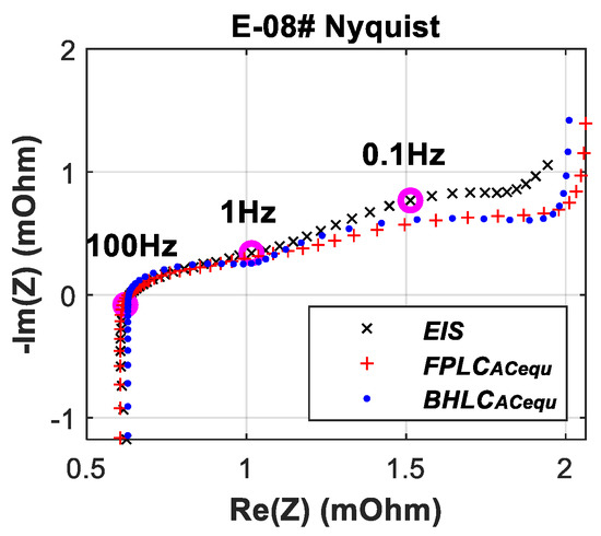
Figure 12.
Experiment Nyquist curve is fitted by FPLCACequ and BHLCACequ.
The Nyquist curve is fitted by FPLCACequ and BHLCACequ through software Zview, and element values in circuits are compared in Table 2. According to test conditions, SoC on batteries are nearly 100%; charge-transfer resistances () for charging of FPLCACequ, are much higher than charge-transfer resistances () for discharging [3,20]. Charge-transfer resistors and double-layer capacitors are directional different. In Figure 4, elements values for simulation are also from Table 2.
Table 2.
Values of elements in FPLCACequ and BHLCACequ for E-08#.
3.3. Results of Extraction Directional Charge-Transfer Resistance in AC Nyquist Curve
In Figure 13c,d, both magnitude and phase bode plots have obvious fitting errors at low frequencies. The errors are mainly due to . is supposed to reduce these errors, but is not convenient for BMS design.

Figure 13.
Linear circuits fitting for bode plots: (a) FPLCACequ fitting in magnitude; (b) BHLCACequ fitting in magnitude; (c) FPLCACequ fitting in phase; (d) BHLCACequ fitting in phase.
The sums of resistances in FPLCACequ are shown in Equations (25)–(28), and their amplitudes in magnitude bode plots are marked in Figure 13a. Based on contacting resistance, each step is corresponding to one charge-transfer resistance, and , , and orderly add up. The sums of resistances in BHLCACequ are shown in Equations (29)–(30), and and orderly add up. They are also marked in Figure 13b. In magnitude bode plots, the asymptotes which roughly outline measured and fitting curves are drawn according to poles and zeros points.
In experiments, batteries’ capacities are almost full-charging; Therefore, charge-transfer resistances for discharging () are smaller than charge-transfer resistances for charging (). Furthermore, if batteries’ SoH is good, for discharging are less than for charging across the broad SoC range; otherwise, when batteries begin to discharge, are used to increase significantly, and the batteries’ terminal voltages drop obviously. Extracting the DC directional charge-transfer resistance from the AC Nyquist curve has engineering significance. In Figure 14, charge-transfer resistances of both FPLCACequ and BHLCACequ fluctuate during accelerated aging tests.

Figure 14.
Elements values in linear circuits fitting for EIS: (a) ; (b) ; (c) ; and (d) in FPLCACequ; (e) ; and (f) in BHLCACequ.
However, increasing the decibel value of the sum of internal resistances, including contacting resistance and charge-transfer resistances, is relatively stable. Each decibel value of each ascending step in the magnitude bode plot is related to one charge-transfer resistance and one asymptotic line configured by the pole–zero pair in Figure 13a,b. Bode plots change during accelerated aging tests, but orders of FPLCACequ and BHLCACequ are fixed. Therefore, the scale ratio of the decibel value of each ascending step should be stable. Three ratios of decibel value of ascending steps in FPLCACequ, as Equations (31)–(33), are stable between 0.2 and 2.5 in Figure 15; these three steps are different and the ratios decrease from to . The ratio of decibel value of ascending steps in BHLCACequ, as Equation (34), is stable between one and two in Figure 15.

Figure 15.
Ratio of decibel values of ascending steps of the sum of internal resistances: (a) E-52#; (b) E-11#; (c) E-02#; and (d) E-20#.
In magnitude bode plots of Figure 13, the curves drawing from northwest at low frequency to southeast at high frequency are roughly straight lines. Assuming there is a four-bit analog-to-digital converter for ideal straight-line input, its interpretation steps should be defined as : : : . So does a two-bit analog-to-digital converter, as : . The scale ratios of adjacent steps are two to maximize the measurement range. However, the curves in magnitude bode plots are not ideal straight lines, so the scale ratio of adjacent sums of resistances is not as ideal as two. Figure 15 shows a similar law, as the numbers of steps are strictly limited by FPLCACequ and BHLCACequ. From this perspective, expansions and contractions of magnitude bode plots are reflecting on the sum of internal resistances, and resistances obtained in Nyquist are viable to characterize batteries’ SoH.
In Figure 16, contacting resistances and stray inductances of both FPLCACequ and BHLCACequ are very close. High frequency zero points, determined by contacting resistances and stray inductances as Equation (35), are very close in both FPLCACequ and BHLCACequ.
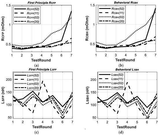
Figure 16.
Elements values in linear circuits fitting for EIS: (a) RCFP in FPLCACequ; (b) RCBH in BHLCACequ; (c) LSFP in FPLCACequ; (d) LSBH in BHLCACequ.
The FPLCACequ provides DC directional charge-transfer resistances for charging and discharging. Characteristic charge-transfer resistances on the electrode–electrolyte interface are calculated in [29] by FPLCACequ. During the first four accelerated aging tests rounds, positive characteristic charge-transfer resistances of E-02# are always high, and positive characteristic charge-transfer resistances of E-20# are climbing up in Figure 17a [29]. The positive characteristic charge-transfer resistances of E-52# reach a maximum at the fifth test round in Figure 17a [29]. The increasing of positive characteristic charge-transfer resistances represents non-cohesion of active mass of the positive electrode [4]; all these changes are early warnings of subsequent capacity degradation in Figure 9a. These early warnings are not be interpreted in BHLCACequ; the positive/negative behavioral charge-transfer resistances and contacting resistances of E-20# and E-11# fluctuate close to each other in Figure 14e,f and Figure 16b. Charge-transfer resistances in FPLCACequ, compared in BHLCACequ, characterize inside physical and electrochemical changes.
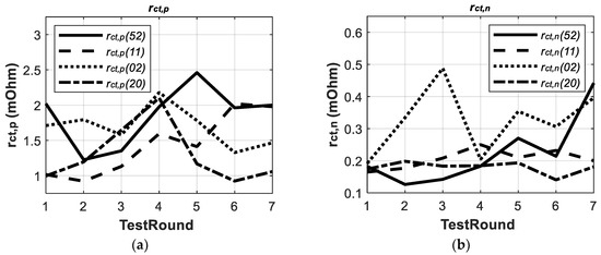
Figure 17.
Characteristic charge-transfer resistances in FPLCACequ: (a) of positive electrode; (b) of negative electrode. [29].
3.4. Boundary between First Principle Circuits on Batteries in Field Applications
The steady-state DC static voltage responses appear in experiments in the literature [2,3,20], and the steady-state DC static voltage response is nearly zero in experiments of this paper. In field applications, injections of battery terminals are generally constant DC or stable AC currents; engineering separation between FPLCACequ and FPLCDCequ can mainly be determined by time constants of injection currents. Time constants of currents are compared with time constants of impedances on electrode–electrolyte interfaces, especially of positive electrodes. If the time constants of impedances are much larger than the time constants of currents, FPLCACequ is suitable; if the time constants of impedances are much smaller than the time constants of currents [20], FPLCDCequ is more suitable.
The practical rule of the boundary is considered in perspective of limit, but not from the perspective of arbitrary injections. This practical rule of option between these two first principle circuits has not been mentioned before. Boundaries of separation between FPLCACequ and FPLCDCequ may be gradual or abrupt, and the boundaries patterns still need further research.
The purpose of this article is to establish a one-to-one relationship between the Nyquist curve and FPLCDCequ. The steady-state DC static voltage response in Nyquist is zero after software and hardware filtering. The FPLCACequ satisfies requirements in Section 2.1 and matches experimental results.
3.5. Comparing with Nonlinear Models
Average switch modeling is proposed to obtain FPLCACequ, and circuit orders are increased to include directional charge-transfer resistances. Average switch modeling can be extended to nonlinear electrochemical circuits. Nonlinear electrochemical elements, such as the constant phase element and Warburg element, are totally nondirectional and frequency-dependent [1], and they mainly represent the electrolyte diffusion process [24]. So, linear charge-transfer resistances for charging/discharging in nonlinear electrochemical circuits are the same as in FPLCACequ.
Figure 18a is an AC equivalent first principle nonlinear circuit (FPNLCACequ in Equation (36)), and Figure 18b is an AC equivalent behavioral nonlinear circuit (BHNLCACequ in Equation (37)) on batteries. The Nyquist of the EIS from the same 500 Ah battery (model GFM-500R and number E-8#), is plotted with diagonal cross points in Figure 19; in Figure 19, the fitting curve of FPNLCACequ is plotted with cross points, and the fitting curve of BHNLCACequ is plotted with dot points.

Figure 18.
Nonlinear circuits fitting for EIS: (a) FPNLCACequ; (b) BHNLCACequ.

Figure 19.
Experimental Nyquist curve is fitted by FPNLCACequ and BHNLCACequ.
The Nyquist is fitted by FPNLCACequ and BHNLCACequ through software Zview, and element values in circuits are compared in Table 3. In Figure 19, both nonlinear circuits have obvious fitting errors at low frequencies. The errors are mainly due to , and is supposed to reduce these errors, but this is not mainly a concern in this paper.
Table 3.
Values of elements in Figure 18.
4. Conclusions
Impedances on electrode–electrolyte interface of FPLCACequ, established by average switch modeling, have a one-to-one relationship with impedances on the electrode–electrolyte interface of FPLCDCequ. Therefore, a unique physical bridge from AC Nyquist, fitting by FPLCACequ, to the directional DC charge-transfer resistance of FPLCDCequ is proposed. Steady-state AC fundamental responses of FPLCACequ are verified by theoretically derived time domain simulation and experiments in this paper.
This novel method provides an opportunity to review previous conclusions between BHLCACequ and SoC/SoH with directional DC charge-transfer resistances, and this is going to be researched further by authors.
Author Contributions
Conceptualization, W.W., W.Y., W.C., Z.M. and Z.L.; data curation, W.W., W.Y., W.C. and D.C.; formal analysis, W.W., W.Y., W.C., D.C. and Z.L.; funding acquisition, W.Y. and Z.L.; investigation, W.W., W.Y., Z.M. and Z.L.; methodology, W.W., W.Y., W.C., Z.M. and Z.L.; project administration, W.Y., W.C., D.C. and Z.L.; resources, W.Y., W.C., D.C., Z.M. and Z.L.; software, W.W. and W.Y.; supervision, W.Y. and Z.L.; validation, W.W., W.C. and D.C.; visualization, W.W., W.C. and D.C.; writing—original draft, W.W., W.Y. and Z.L.; writing—review and editing, W.W., W.Y. and Z.L. All authors have read and agreed to the published version of the manuscript.
Funding
The research presented within this paper is supported by the National Natural Science Foundation of China under grants (51677168), and the National Major Science and Technology Projects of China under grants (2017ZX06002009).
Acknowledgments
Thanks to Cheng Cheng and Hanchuan Huang, from Zhejiang Narada Power Source Co., Ltd., Yedong Zhang and Yao Lu, from Polytechnic Institute of Zhejiang University, for helpful discussions and experimental configuration.
Conflicts of Interest
The authors declare no conflict of interest. The funders had no role in the design of the study; in the collection, analyses, or interpretation of data; in the writing of the manuscript, or in the decision to publish the results.
Appendix A
Table A1.
The physical meanings of elements and abbreviations.
Table A1.
The physical meanings of elements and abbreviations.
| Item | Elements | Physical Meanings |
|---|---|---|
| 1 | EIS | electrochemical impedance spectroscopy |
| 2 | FPLCDCequ | DC equivalent first principle linear circuit |
| 3 | SoH | state of health |
| 4 | FPLCACequ | AC equivalent first principle linear circuit |
| 5 | BMS | battery management system |
| 6 | SoC | state of charge |
| 7 | BHLCACequ | AC equivalent behavioral linear circuit |
| 8 | contacting resistor | |
| 9 | stray inductor | |
| 10 | electrolyte bulk capacitor | |
| 11 | charge-transfer resistor | |
| 12 | double-layer capacitor | |
| 13 | impedance on electrode–electrolyte interface | |
| 14 | charge-transfer resistor for charging on electrode–electrolyte interface of positive electrode | |
| 15 | charge-transfer resistor for charging on electrode–electrolyte interface of negative electrode | |
| 16 | charge-transfer resistor for discharging on electrode–electrolyte interface of positive electrode | |
| 17 | charge-transfer resistor for discharging on electrode–electrolyte interface of negative electrode | |
| 18 | double-layer capacitor for both charging and discharging on electrode–electrolyte interface of positive electrode | |
| 19 | double-layer capacitor for both charging and discharging on electrode–electrolyte interface of negative electrode | |
| 20 | double-layer capacitor for charging on electrode–electrolyte interface of positive electrode | |
| 21 | double-layer capacitor for charging on electrode–electrolyte interface of negative electrode | |
| 22 | double-layer capacitor for discharging on electrode–electrolyte interface of positive electrode | |
| 23 | double-layer capacitor for discharging on electrode–electrolyte interface of negative electrode | |
| 24 | fixed frequency sinusoidal current, excited from electrochemical workstation, is the amplitude and is the static angle (rad) in rotating space vector plane | |
| 25 | linear impedances for charging on electrode–electrolyte interfaces of both positive and negative electrodes, is the amplitude and is the static angle (rad) in rotating space vector plane | |
| 26 | linear impedances for discharging on electrode–electrolyte interfaces of both positive and negative electrodes, is the amplitude and is the static angle (rad) in rotating space vector plane | |
| 27 | equivalent linear impedances on electrode–electrolyte interfaces of both positive and negative electrodes, is the amplitude and is the static angle (rad) in rotating space vector plane | |
| 28 | charging voltage vector, steady-state AC fundamental response of linear impedances , in rotating space vector plane | |
| 29 | discharging voltage vector, steady-state AC fundamental voltage response of linear impedances , in rotating space vector plane | |
| 30 | new charging voltage vector, half amplitude of , in rotating space vector plane | |
| 31 | new discharging voltage vector, half amplitude of , in rotating space vector plane | |
| 32 | target voltage vector, steady-state AC fundamental response of impedance , in rotating space vector plane | |
| 33 | fixed period of sinusoidal current, excited from electrochemical workstation | |
| 34 | transient voltage responses of impedances for charging on electrode–electrolyte interfaces of both positive and negative electrodes | |
| 35 | transient voltage responses of impedances for discharging on electrode–electrolyte interfaces of both positive and negative electrodes | |
| 36 | average voltage response of impedances for charging on electrode–electrolyte interfaces of both positive and negative electrodes during the period | |
| 37 | average voltage response of impedances for discharging on electrode–electrolyte interfaces of both positive and negative electrodes during the period | |
| 38 | complex variable in transfer function | |
| 39 | transfer function of band pass filter | |
| 40 | quality factor of band pass filter | |
| 41 | electrical angular velocity of sinusoidal current, excited from electrochemical workstation | |
| 42 | linear contacting resistance, reflecting conductivity of path which currents flowing along terminals, cell connectors, plate connectors, electrodes, and electrolyte; is the amplitude and 0 is the static angle (rad) in rotating space vector plane | |
| 43 | linear stray inductance, in series with linear contacting resistance; is the amplitude and is the static angle (rad) in rotating space vector plane | |
| 44 | linear electrolyte bulk capacitance, reflecting capacity characteristics of bulk electrolyte; is the amplitude and is the static angle (rad) in rotating space vector plane | |
| 45 | contacting resistance voltage vector, steady-state AC fundamental responses on linear contacting resistance | |
| 46 | transient voltage responses of linear contacting resistance | |
| 47 | average voltage response of linear contacting resistance during the period | |
| 48 | inductance voltage vector, steady-state AC fundamental responses on linear stray inductance | |
| 49 | transient voltage responses of linear stray inductance | |
| 50 | average voltage response of linear stray inductance during the period | |
| 51 | electrolyte bulk capacitance voltage vector, steady-state AC fundamental responses on linear electrolyte bulk capacitance | |
| 52 | transient voltage responses of linear electrolyte bulk capacitance | |
| 53 | average voltage response of linear electrolyte bulk capacitance during the period | |
| 54 | Warburg impedance | |
| 55 | diffusion constant of Warburg impedance | |
| 56 | ohmic constant of Warburg impedance | |
| 57 | Constant Phase Element | |
| 58 | diffusion constant of Constant Phase Element | |
| 59 | P | constant of power function |
| 60 | charge-transfer resistor for both charging and discharging on electrode–electrolyte interface of positive electrode | |
| 61 | charge-transfer resistor for both charging and discharging on electrode–electrolyte interface of negative electrode | |
| 62 | linear contacting resistance of FPLCACequ | |
| 63 | linear contacting resistance of BHLCACequ | |
| 64 | linear stray inductance of FPLCACequ | |
| 65 | linear stray inductance of BHLCACequ | |
| 66 | FPNLCACequ | AC equivalent first principle nonlinear circuit |
| 67 | BHNLCACequ | AC equivalent behavioral nonlinear circuit |
References
- Kwiecien, M.; Badeda, J.; Huck, M.; Komut, K.; Duman, D.; Sauer, D.U. Determination of SoH of Lead-Acid Batteries by Electrochemical Impedance Spectroscopy. Appl. Sci. 2018, 8, 873. [Google Scholar] [CrossRef]
- Srinivasan, V.; Wang, G.Q.; Wang, C.Y. Mathematical Modeling of Current-Interrupt and Pulse Operation of Valve-Regulated Lead Acid Cells. J. Electrochem. Soc. 2003, 150, A316–A325. [Google Scholar] [CrossRef]
- Rahn, C.D.; Wang, C.Y. Battery Systems Engineering; John Wiley& Sons: New York, NY, USA, 2013; pp. 4–6, 27–28, 102–103, 122. [Google Scholar] [CrossRef]
- Brik, K.; Ammar, F.B. Causal Tree Analysis of Depth Degradation of the Lead Acid Battery. J. Power Sources 2013, 228, 39–46. [Google Scholar] [CrossRef]
- Boškoski, P.; Debenjak, A.; Boshkoska, B.M. Fast Electrochemical Impedance Spectroscopy; Springer: Cham, Switzerland, 2017; p. 1. [Google Scholar] [CrossRef]
- Kwiecien, M.; Huck, M.; Badeda, J.; Zorer, C.; Komut, K.; Yu, Q.; Sauer, D.U. Variation of Impedance in Lead-Acid Batteries in the Presence of Acid Stratification. Appl. Sci. 2018, 8, 1018. [Google Scholar] [CrossRef]
- Shen, Z.; Rahn, C.D. Physics-Based Model of a Valve-Regulated Lead-Acid Battery and an Equivalent Circuit. J. Dyn. Syst. Meas. Control 2013, 135, 041011. [Google Scholar] [CrossRef]
- Sadabadi, K.K.; Ramesh, P.; Tulpule, P.; Rizzoni, G. Design and Calibration of a Semi-empirical Model for Capturing Dominant Aging Mechanisms of a PbA Battery. J. Energy Storage 2019, 24, 100789. [Google Scholar] [CrossRef]
- Yahmadi, R.; Brik, K.; Ammar, F.B. Causal Tree Analysis for Quality Control of the Lead Acid Battery manufacturing process. Int. J. Energy Res. 2018, 42, 1738–1759. [Google Scholar] [CrossRef]
- Kwiecien, M.; Huck, M.; Badeda, J.; Sauer, D.U. Correct Processing of Impedance Spectra for Lead-acid Batteries to Parameterize the Charge-Transfer Process. J. Appl. Electrochem. 2018, 48, 885–900. [Google Scholar] [CrossRef]
- Badeda, J.; Kwiecien, M.; Schulte, D.; Sauer, D.U. Battery State Estimation for Lead-Acid Batteries under Float Charge Conditions by Impedance: Benchmark of Common Detection Methods. Appl. Sci. 2018, 8, 1308. [Google Scholar] [CrossRef]
- Meiwes, H.B.; Kowal, J.; Sauer, D.U.; Karden, E. Influence of Measurement Procedure on Quality of Impedance Spectra on Lead–acid Batteries. J. Power Sources 2011, 196, 10415–10423. [Google Scholar] [CrossRef]
- Ansari, A.B.; Vahid, E.; Torabi, F. Discharge, Rest and Charge Simulation of Lead-acid Batteries Using an Efficient Reduced Order Model Based on Proper Orthogonal Decomposition. Appl. Energy 2016, 173, 152–167. [Google Scholar] [CrossRef]
- Cao, Y.; Kroeze, R.C.; Krein, P.T. Multi-timescale Parametric Electrical Battery Model for Use in Dynamic Electric Vehicle Simulations. IEEE Trans. Transp. Electrif. 2016, 2, 432–442. [Google Scholar] [CrossRef]
- Aksakal, C.; Sisman, A. On the Compatibility of Electric Equivalent Circuit Models for Enhanced Flooded Lead Acid Batteries Based on Electrochemical Impedance Spectroscopy. Energies 2018, 11, 118. [Google Scholar] [CrossRef]
- Monfared, N.A.; Gharib, N.; Moqtaderi, H.; Hejabi, M.; Amiri, M.; Torabi, F.; Mosahebi, A. Prediction of State-of-Charge Effects on Lead-Acid Battery Characteristics Using Neural Network Parameter Modifier. J. Power Sources 2006, 158, 932–935. [Google Scholar] [CrossRef]
- Piłatowicz, G.; Marongiu, A.; Drillkens, J.; Sinhuber, P.; Sauer, D.U. A Critical Overview of Definitions and Determination Techniques of the Internal Resistance Using Lithium-Ion, Lead-Acid, Nickel Metal-Hydride Batteries and Electrochemical Double-Layer Capacitors as Examples. J. Power Sources 2015, 296, 365–376. [Google Scholar] [CrossRef]
- Cacciato, M.; Nobile, G.; Scarcella, G.; Scelba, G. Real-Time Model-Based Estimation of SOC and SOH for Energy Storage Systems. IEEE Trans. Power Electron. 2016, 32, 794–803. [Google Scholar] [CrossRef]
- Karden, E. Using Low-Frequency Impedance Spectroscopy for Characterization, Monitoring, and Modeling of Industrial Batteries. Ph.D. Thesis, RWTH Aachen University, Aachen, Germany, December 2001; pp. 13–24. [Google Scholar]
- Shen, Z. Control-Oriented Modeling, State-of-Charge, State-of-Health, and Parameter Estimation of Batteries. Ph.D. Thesis, The Pennsylvania State University, University Park, PA, USA, August 2013; pp. 23–27, 28–30. [Google Scholar]
- Nejad, S. Adaptive Techniques for Estimation and Online Monitoring of Battery Energy Storage Devices. Ph.D. Thesis, University of Sheffield, Sheffield, UK, May 2017; pp. 161–169. [Google Scholar]
- Gu, W.B.; Wang, G.Q.; Wang, C.Y. Modeling the Overcharge Process of VRLA Batteries. J. Power Sources 2002, 108, 174–184. [Google Scholar] [CrossRef]
- Erickson, R.W.; Maksimovic, D. Fundamentals of Power Electronics, 2nd ed.; Springer: New York, NY, USA, 2001; pp. 13–15, 45–50. [Google Scholar]
- Barsoukov, E.; Macdonald, J.R. Impedance Spectroscopy Theory, Experiment, and Applications, 2nd ed.; John Wiley& Sons: New York, NY, USA, 2005; pp. 4–7. [Google Scholar]
- Berndt, D.; Teutsch, U. Float Charging of Valve-Regulated Lead-Acid Batteries: A Balancing Act between Secondary Reactions. J. Electrochem. Soc. 1996, 143, 790. [Google Scholar] [CrossRef]
- Wu, B.; Narimani, M. High-Power Converters and AC Drives, 2nd ed.; John Wiley& Sons: New York, NY, USA, 2017; pp. 101–105. [Google Scholar]
- Wang, C.Y.; Xia, J.K.; Sun, Y.B. Modern Control Technique of Electric Machines; China Machine Press: Beijing, China, 2008; p. 41. [Google Scholar]
- Mauracher, P.; Karden, E. Dynamic Modelling of Lead/Acid Batteries Using Impedance Spectroscopy for Parameter Identification. J. Power Sources 1997, 67, 69–84. [Google Scholar] [CrossRef]
- Wang, W.B.; Yao, W.X.; Chen, W.; Chen, D.; Lu, Z.Y. Characteristic Charge Transfer Resistance of Electrodes on Lead-Acid Batteries. J. Electrochem. Soc. 2020, 167, 040515. [Google Scholar] [CrossRef]


© 2020 by the authors. Licensee MDPI, Basel, Switzerland. This article is an open access article distributed under the terms and conditions of the Creative Commons Attribution (CC BY) license (http://creativecommons.org/licenses/by/4.0/).