Article

Optimization of the Secondary Optical Element of a Hybrid Concentrator Photovoltaic Module Considering the Effective Absorption Wavelength Range

1
School of Electrical Engineering and Computer Science, Gwangju Institute of Science and Technology, Gwangju 61005, Korea
2
Research Institute for Solar and Sustainable Energies, Gwangju Institute of Science and Technology, Gwangju 61005, Korea
3
Korea Advanced Nano Fab Center, Suwon 16229, Korea
4
194 Central-ro, Yeonsu-gu, Incheon 22003, Korea
*
Author to whom correspondence should be addressed.
These authors contribute equally to this work.
Appl. Sci. 2020, 10(6), 2051; https://doi.org/10.3390/app10062051
Submission received: 27 February 2020 / Revised: 8 March 2020 / Accepted: 10 March 2020 / Published: 18 March 2020
(This article belongs to the Section Energy Science and Technology)

Abstract

:
Hybrid concentrator photovoltaic (CPV) architectures that combine CPV modules with low-cost solar cells have the advantage of functioning well in modest direct normal irradiance (DNI) regions as well as high-DNI regions, where these architectures allow for higher performance in a limited space. For higher performance of a hybrid CPV module, we optimized the secondary optical element (SOE) using raytracing software and conducted experimental measurements that consider the effective wavelength range. Our experiments with the optimized SOE (θ = 30°, h = 15 mm) demonstrated a maximum output power on the triple-junction cell and polycrystalline silicon cell of 212.8 W/m2 and 5.14 W/m2, respectively.

1. Introduction

The origin of the technique to obtain solar energy effectively using a concentrator is considered to be a combination of reflector and thermal collector, since the late 1970s [1,2]. The technique has been further advanced, and concentrator photovoltaic (CPV) modules have been actively studied to reduce costs and improve performance [3,4,5,6,7,8,9,10,11,12]. CPV modules are highly efficient power generators in high-direct normal irradiance (DNI) regions near the equator, but less effective in the global normal irradiance (GNI) mid-latitude regions, where these modules do not perform as well as flat photovoltaic (PV) modules. To overcome these limitations, several researchers have studied hybrid CPV modules that combine a CPV module with low-cost PV modules [13,14,15,16], since these hybrid CPV architectures can collect sunlight in modest-DNI regions, which allows the same solar module design regardless of region. In addition, hybrid CPV modules can maximize power generation in the high-DNI regions without requiring as much volume, since they absorb scattered light more efficiently [11]. Lee et al. experimentally analyzed two types of hybrid CPV modules with concentration ratios of 18X and 1000X and showed high power generation efficiency [12]. Yamada et al. combined the two-terminal triple-junction (TJ) solar cell and bifacial crystalline silicon solar cell for their hybrid CPV modules, and performed analyses based on the (GNI–DNI)/GNI ratio [13]. While many studies have been conducted on the secondary optical elements (SOEs) used in conventional CPV modules [17,18,19], we have not seen a study on the SOEs of hybrid CPV modules. In this paper, we analyzed the mirror-type SOE for the hybrid CPV modules and optimized it through simulation and experimental measurements under high-DNI conditions. Especially analyzed were the shading losses of the silicon solar cells by the SOEs on the hybrid CPV modules. In addition, the two-terminal TJ solar cell, mainly used in CPV modules, cannot convert light of wavelength above about 1.3 μm, due to the current limit of the top cell [20,21]. This longer wavelength light is also not absorbed by the silicon solar cells in the hybrid CPV modules around the TJ solar cell. For this reason, we considered the effective wavelength range for the optimization of the SOE. These hybrid CPV modules are promising as the next generation of the thermal collector system.

2. Simulation Setup

The angle at which sunlight refracts from the primary optical element (POE) of the hybrid CPV module depends on the wavelength, which creates chromatic aberration [22]. In addition, infrared rays with wavelengths above 1.3 μm are not absorbed in either TJ solar cells or silicon solar cells, due to current limits in the top cell and limited semiconductor bandgap energy, respectively. Therefore, we considered the effective wavelength range while we optimized the SOE of the hybrid CPV module. To analyze the hybrid CPV architecture, we used the TracePro (Lambda Research Corporation, Littleton, Massachusetts, USA) raytracing software, based on a Monte Carlo method with the xenon lamp spectrum (1000 W/m2), to create the three-dimensional model shown in Figure 1. Assuming modest-DNI regions, sunlight was designed with 80% DNI and 20% diffuse light. We selected a 254 × 254 × 3 mm3 Fresnel lens made of polymethyl methacrylate (PMMA; refractive index = 1.49 at 500 nm) and an Al mirror (92% reflective at 500 nm) as the POE and SOE, respectively. The focal length of the POE was 250 mm, and the body size was 254 × 254 × 253 mm3. We placed the silicon solar cell 8 mm away from the TJ solar cell in position #2, and the spacing between the silicon solar cells was 3 mm. For ease of cleaning the module, the flat side of the Fresnel lens faced the sun, and the stepped side faced the solar cells. We placed a high-performance TJ solar cell (10 × 10 mm2; concentration ratio = 645X) at the center of the hybrid CPV module to collect the concentrated DNI. Around the TJ solar cell, we spread 12 silicon solar cells (80 × 55 mm2) to collect light that was scattered from the concentrator and diffuse solar irradiance.

3. Simulations

3.1. Optimization of SOE Design

Figure 2 shows our SOE designs with different angles when placed on the TJ solar cells. At this point, we fixed the SOE height at 15 mm and maintained a constant distance between the Fresnel lens and the TJ solar cell. Using these SOEs, we calculated the irradiance on the TJ solar cell and on the 12 silicon solar cells (positions #1 to #12 in Table 1). We also analyzed the irradiance by dividing the results into an effective wavelength range (0.3–1.299 μm) and a lossy wavelength range (1.3–2.5 μm). The irradiance on the TJ solar cell in the effective wavelength range was minimized for a perpendicular SOE (326.8 W/m2), and maximized when θ = 30° (606.2 W/m2); when the angle is greater than 30°, the light is reflected and the intensity of the light is reduced. Although the sum of power in the effective and lossy wavelength ranges was higher in the θ = 40° case than the θ = 30° case, the ETJ,loss/ETJ,eff ratio indicates that the loss ratio of the θ = 40° (6.9%) case was higher than that of the θ = 30° (5.7%) case, so θ = 30° seems more optimal. In addition, higher SOE angles in the silicon solar cell will decrease the irradiance, due to shading from the SOE.
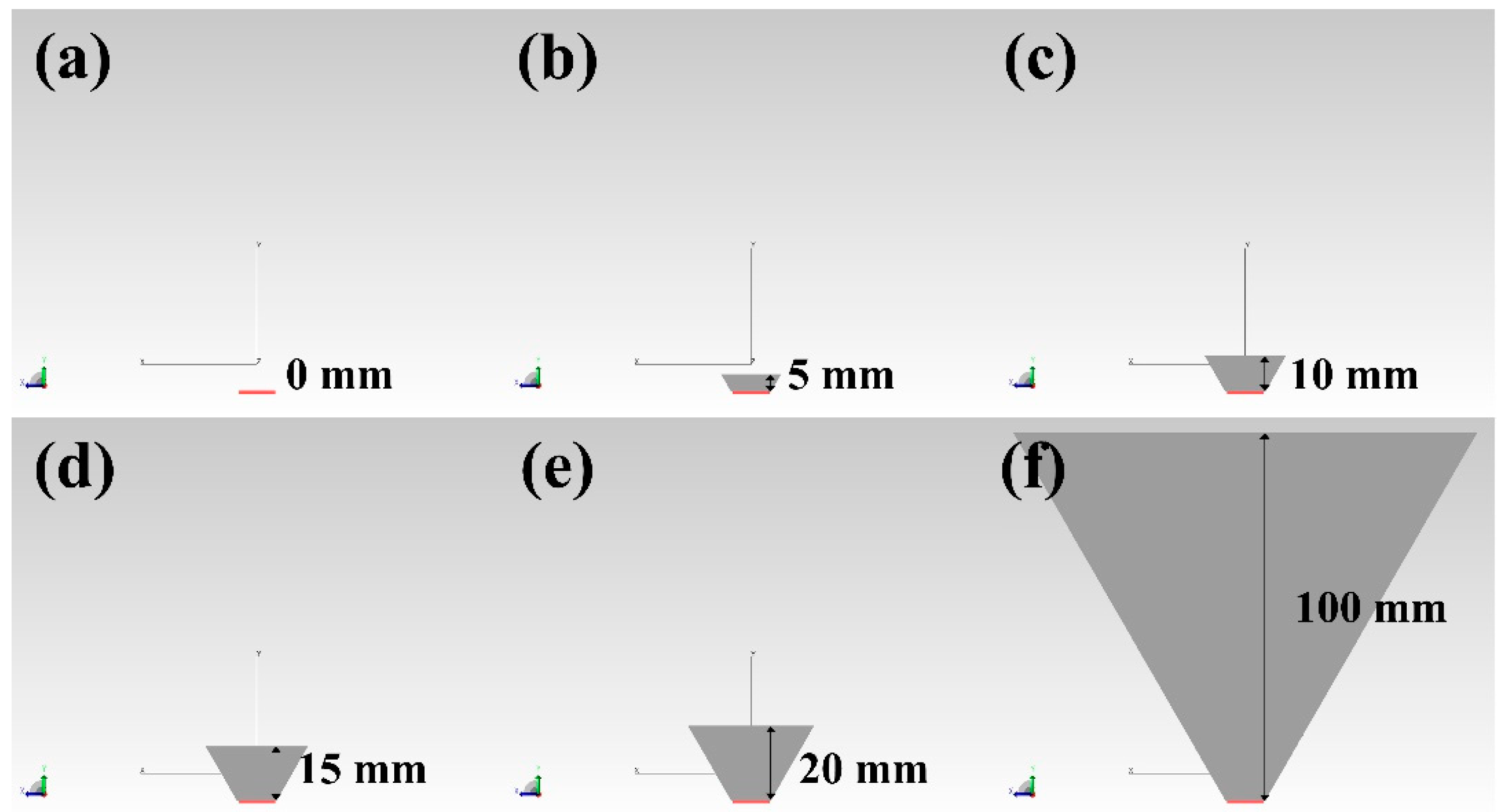
Next, we analyzed the irradiance with a fixed 30° SOE angle as we varied the SOE height from 0 mm to 100 mm, as shown in Figure 3 and Table 2. Since the conversion efficiency of the TJ solar cell is better than the low-cost silicon solar cells, the hybrid CPV module configuration should be adjusted for better light concentration. When the height was zero (i.e., no SOE), we calculated powers of 590.8 W/m2 and 131.2 W/m2 on the TJ solar cell and the silicon solar cells, respectively. Although larger heights led to higher power values on the TJ solar cell, the irradiance within the lossy wavelength range increased faster than the irradiance within the effective wavelength range, as shown by the increasing ETJ,loss/ETJ,eff ratio. Moreover, since taller SOEs increase the production cost and maximize shading, moderately tall SOEs are more desirable. While the irradiance on the silicon solar cells was 127.4 W/m2 for h = 15 mm, the irradiances on the silicon solar cells were 124.8 W/m2 and 85.4 W/m2 for h = 20 and 100 mm, respectively, due to the shading on the SOEs. Therefore, we focused our subsequent simulations and experimental measurements on the case of h = 15 mm and θ = 30°.

3.2. Irradiance Distributions

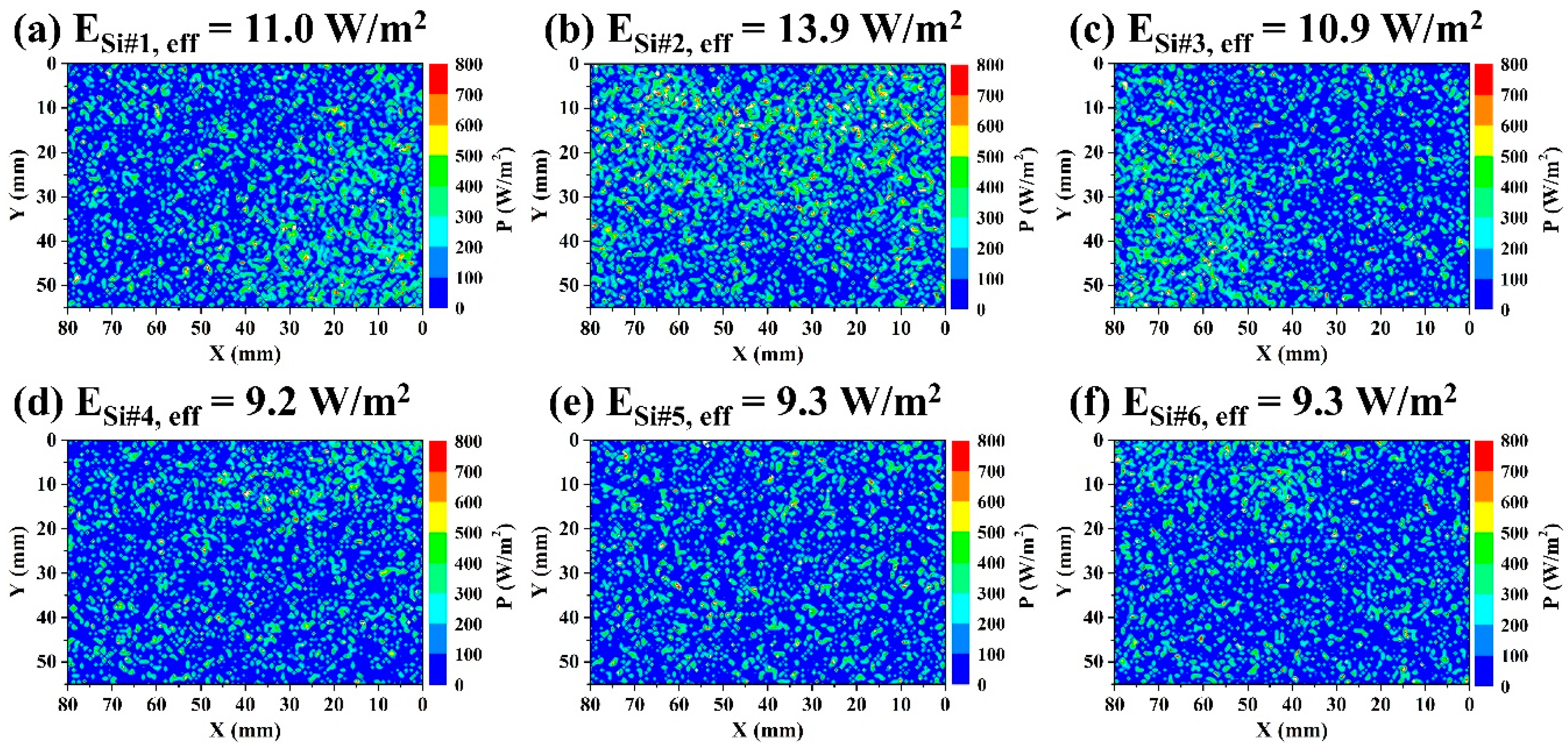
Next, we analyzed the light distribution of a hybrid CPV module with a pyramidal SOE (θ = 30°, h = 15 mm). Figure 4 shows the simulation results for the six silicon solar cells using the layout from Figure 1a. Since the hybrid CPV module is symmetric, we only needed to identify six of the 12 silicon solar cells. The irradiances on the Si #7–12 were 10.8 W/m2, 13.8 W/m2, 11.0 W/m2, 9.2 W/m2, 9.2 W/m2, and 9.3 W/m2, respectively. We analyzed the irradiances and irradiance distributions using the effective wavelength range. Although single crystal silicon modules are more efficient than smaller polycrystalline silicon solar cells, we simulated polycrystalline silicon solar cells to better match the experimental measurements to follow. Figure 4b shows that, although the silicon solar cell placed next to the SOE was affected by the shadow of the SOE, that solar cell still collected the highest power (13.9 W/m2). In addition, the silicon solar cells placed away from the CPV also showed irradiance of at least 9.2 W/m2 by absorbing diffuse light. Considering that hybrid CPV modules are constructed as arrays, we used a square Fresnel lens, which seems to have affected the irradiance distribution.
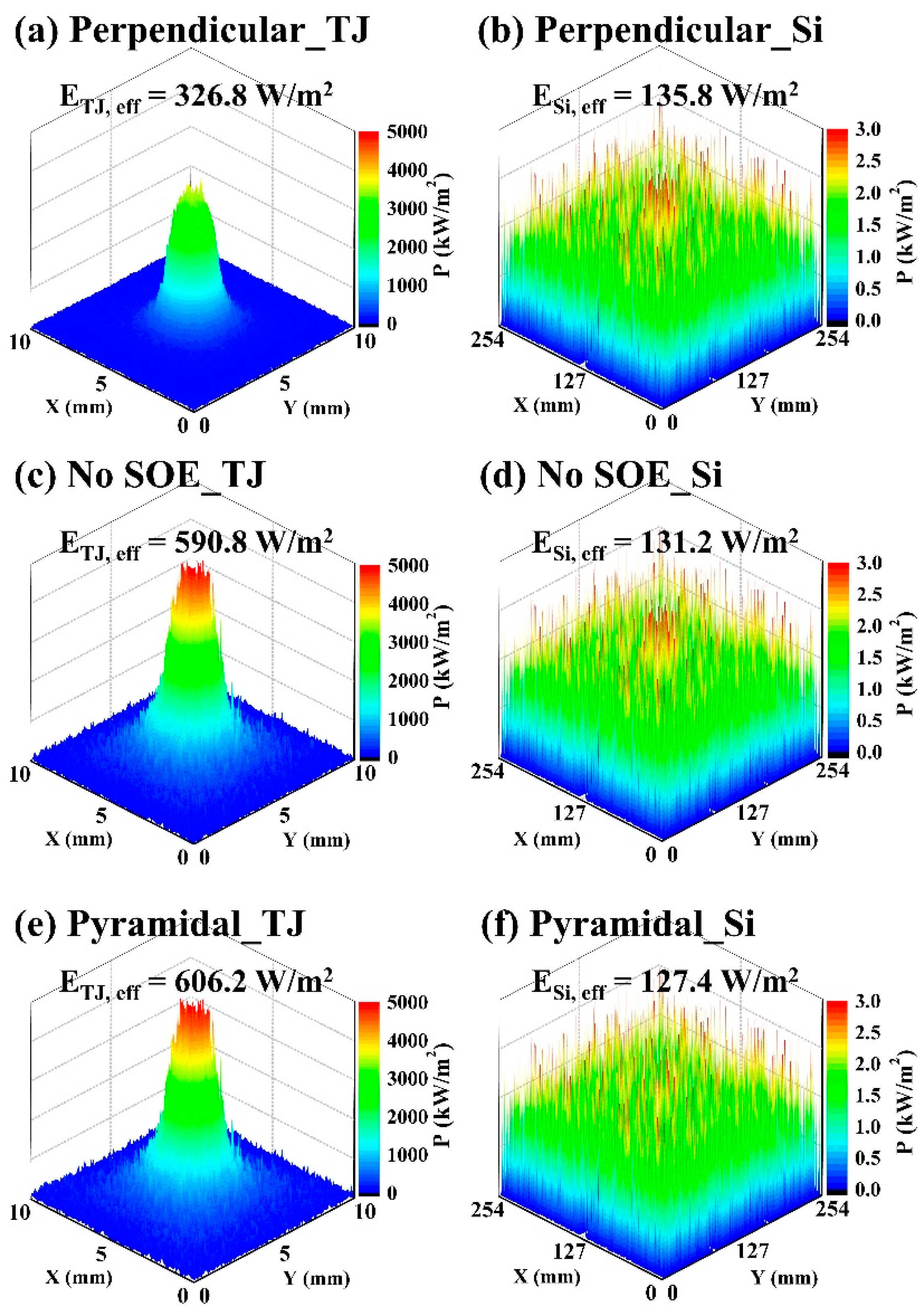
To identify the irradiance distribution of the TJ and silicon solar cells according to the design of the SOE, we examined the three cases shown in Figure 5. In the perpendicular SOE, the concentrated power on the TJ solar cell was the smallest (326.8 W/m2), while the irradiance on the silicon solar cells was the largest (135.8 W/m2). Without an SOE, the irradiance on the TJ and silicon solar cells were 590.8 W/m2 and 131.2 W/m2, respectively. When using the pyramidal SOE optimized above, we saw the largest power (606.2 W/m2) concentrated on the TJ solar cell, and the smallest power (127.4 W/m2) on the silicon solar cell. The solar cell conversion efficiency relation is:
η = P M A X P i n p u t × 100   ( % )
where η is the conversion efficiency, PMAX is the maximum output power, and Pinput is the input optical power. Therefore, assuming a TJ solar cell conversion efficiency of 38.5% when using a pyramidal SOE, we calculate PMAX as 233.4 W/m2. In addition, assuming an 18% conversion efficiency for the polycrystalline silicon solar cell, we expect to generate 22.9 W/m2 of electric power. Using the same assumption, we predict maximum output powers of 125.8 W/m2 and 24.4 W/m2 for the perpendicular SOE, and maximum output powers of 227.5 W/m2 and 23.6 W/m2 for the no SOE case. We will compare these predictions with experimental measurements in the next section.

4. Experimental Measurements

To supplement the simulation results with experimental measurements, we constructed the hybrid CPV module analyzed above, and show the results in Figure 6 and Table 3. We used a solar simulator (WACOM, WXS-450S-65), xenon lamp (6500 W), Fresnel lens (PMMA, 254 × 254 × 3 mm3), GaInP/GaInAs/Ge triple-junction solar cell (Spectrolab, CDO-100-C3MJ, 10 × 10 mm2), polycrystalline silicon solar cells (Zhiwang, 80 × 55 mm2), and a heat sink in the setup for this measurement. Figure 6g shows the I-V and P-V curves of the TJ solar cells and the hybrid CPV module, demonstrating that the pyramidal SOE had the highest maximum output power of 212.8 W/m2. The hybrid CPV module without an SOE had the next highest power (181.5 W/m2), followed by the perpendicular SOE (149.0 W/m2). The perpendicular SOE had the lowest PMAX due to its narrow entrance, but it was expected to act as a homogenizer well. Although these values are slightly lower than the results calculated above, they show a similar relationship. The I-V and P-V curves for the polycrystalline silicon solar cells in Figure 6h demonstrate that the sum of maximum output power for the pyramidal SOE was the lowest at 5.14 W/m2. The perpendicular SOE and the no SOE cases attained the sum of maximum output power values of 5.67 W/m2 and 5.99 W/m2, respectively. From Figure 4, the PMAX of the polycrystalline silicon solar cells with an 18% conversion efficiency were found to be 1.98 W/m2, 2.5 W/m2, 1.96 W/m2, 1.66 W/m2, 1.67 W/m2, and 1.67 W/m2, respectively. On the other hand, the experimental measurements obtained PMAX of 0.42 W/m2, 0.76 W/m2, 0.4 W/m2, 0.33 W/m2, 0.32 W/m2, and 0.33 W/m2, respectively, which were lower than expected. These values are lower than the simulation results, due to the lower proportion of diffuse light in the measurements using the solar simulator. Since the measured output power values were smaller than those predicted by the simulation, we need to include diffuse light in the experimental measurement setup for modest-DNI conditions in future tests. Overall, the experimental measurements show similar results to those we calculated using the raytracing simulations, and the hybrid CPV module with the optimized SOE design performed better than the other cases we tested.

5. Conclusions

We demonstrated a hybrid CPV module that combines a TJ solar cell and low-cost silicon solar cells by comparing various SOE designs. When we varied the angle of the SOE between 0° and 50°, our analysis showed an optimized irradiance at 30° on the TJ solar cell in the effective wavelength range. Higher SOE angles increased the irradiance within the lossy wavelength range more than the power within the effective wavelength range, which decreased the performance of the hybrid CPV module. Likewise, taller SOEs also caused larger ETJ,loss/ETJ,eff ratios. We concluded that an SOE with an angle of 30° and a height of 15 mm was the most desirable, with the irradiances of 626.2 W/m2 and 127.4 W/m2 in the effective wavelength range, and a ETJ,loss/ETJ,eff ratio of 5.7%. Next, we compared three SOE configurations for the hybrid CPV module by using simulations and experimental measurements. The perpendicular SOE and the no SOE case generated maximum output powers of 149.0 W/m2 and 181.5 W/m2, respectively, in the TJ solar cell of the fabricated hybrid CPV module. The optimized pyramidal SOE, however, showed a higher maximum output power of 212.8 W/m2 in the TJ solar cell. The hybrid CPV module has potential applications in next-generation power production systems and, therefore, requires more research in the future.

Author Contributions

Conceptualization, W.-L.J.; software, W.-L.J.; writing – original draft, W.-L.J.; writing – review & editing, W.-L.J.; experiments, K.-P.K.; visualization, J.-H.M.; validation, J.-Y.L., S.-H.M., J.-H.P. and J.-H.H.; resources, W.-K.P. and S.Y.; supervision, D.-S.L. All authors have read and agreed to the published version of the manuscript.

Funding

This research was funded by the Korea Institute of Energy Technology Evaluation and Planning (KETEP), the Ministry of Trade, Industry & Energy (MOTIE) of the Republic of Korea, grant number 20183010014310; the GIST Research Institute (GRI), no grant number.

Acknowledgments

The authors would like to thank Eddie Chung at Hanul Solar Energy for his technical support. This work was supported by the Korea Institute of Energy Technology Evaluation and Planning the Ministry of Trade, Industry & Energy of the Republic of Korea (No. 20183010014310), and the GIST Research Institute (GRI) grant funded by the GIST in 2020.

Conflicts of Interest

The authors declare no conflicts of interest.

References

  1. McDaniels, D.K.; Lowndes, D.H.; Mathew, H.; Reynolds, J.; Gray, R. Enhanced solar energy collection using reflector-solar thermal collector combinations. Sol. Energy 1975, 17, 277–283. [Google Scholar] [CrossRef]
  2. Baker, S.; McDaniels, D.K.; Kaehn, H.D.; Lowndes, D.H. Time integrated calculation of the insolation collected by a reflector-collector system. Sol. Energy 1978, 20, 415–417. [Google Scholar] [CrossRef]
  3. Armenta, C.; Vorobieff, P.; Mammoli, A. Summer off-peak performance enhancement for rows of fixed solar thermal collectors using flat reflective surfaces. Sol. Energy 2011, 85, 2041–2052. [Google Scholar] [CrossRef]
  4. Sharaf, O.Z.; Orhan, M.F. Concentrated photovoltaic thermal (CPVT) solar collector systems: Part I—Fundamentals, design considerations and current technologies. Renew. Sustain. Energy Rev. 2015, 50, 1500–1565. [Google Scholar] [CrossRef]
  5. Herrero, R.; Victoria, M.; Domínguez, C.; Askins, S.; Antón, I.; Sala, G. Concentration photovoltaic optical system irradiance distribution measurements and its effect on multi-junction solar cells. Prog. Photovolt. Res. Appl. 2012, 20, 423–430. [Google Scholar] [CrossRef] [Green Version]
  6. Gordon, J.M.; Feuermann, D.; Young, P. Unfolded aplanats for high-concentration photovoltaics. Opt. Lett. 2008, 33, 1114–1116. [Google Scholar] [CrossRef]
  7. Sansoni, P.; Fontani, D.; Francini, F.; Jafrancesco, D.; Pierucci, G.; Lucia, M.D. Technique for outdoor test on concentrating photovoltaic cells. Int. J. Photoenergy 2015, 2015, 1–9. [Google Scholar] [CrossRef]
  8. Sun, Y.; Wang, Y.; Zhu, L.; Yin, B.; Xiang, H.; Huang, Q. Direct liquid-immersion cooling of concentrator silicon solar cells in a linear concentrating photovoltaic receiver. Energy 2014, 65, 264–271. [Google Scholar] [CrossRef]
  9. Narasimman, K.; Selvarasan, I. Design construction and analysis of solar ridge concentrator photovoltaic (PV) system to improve battery charging performance. Ecotoxicol. Environ. Saf. 2016, 127, 187–192. [Google Scholar] [CrossRef] [PubMed]
  10. Wei, A.; Chen, Z.; Sze, J. Planar solar concentrator with a v-groove array for a side-absorption concentrated photovoltaic system. Optik 2016, 127, 10858–10867. [Google Scholar] [CrossRef]
  11. Chen, Y.; Chiang, H. Design of the secondary optical elements for concentrated photovoltaic units with Fresnel Lenses. Appl. Sci. 2015, 5, 770–786. [Google Scholar] [CrossRef] [Green Version]
  12. Nakatani, M.; Yamada, N. Characterization of core-shell spherical lens for microtracking concentrator photovoltaic system. Energies 2019, 12, 3517. [Google Scholar] [CrossRef] [Green Version]
  13. Yamada, N.; Hirai, D. Maximization of conversion efficiency based on global normal irradiance using hybrid concentrator photovoltaic architecture. Prog. Photovolt. Res. Appl. 2016, 24, 846–854. [Google Scholar] [CrossRef]
  14. Lee, K.T.; Yao, Y.; He, J.; Fisher, B.; Sheng, X.; Lumb, M.; Xu, L.; Anderson, M.A.; Scheiman, D.; Han, S.; et al. Concentrator photovoltaic module architectures with capabilities for capture and conversion of full global solar radiation. Proc. Natl. Acad. Sci. USA 2016, 113, E8210–E8218. [Google Scholar] [CrossRef] [PubMed] [Green Version]
  15. Yamada, N.; Okamoto, K. Experimental measurements of a prototype high concentration Fresnel lens CPV module for the harvesting of diffuse solar radiation. Opt. Express 2014, 22, A28–A34. [Google Scholar] [CrossRef] [PubMed]
  16. Araki, K.; Ota, Y.; Lee, K.; Nishioka, K.; Yamaguchi, M. Is It CPV? Yes, But It Is a Partial CPV. In Proceedings of the 13th Conference on Concentrator Photovoltaic Systems, Ottawa, ON, Canada, 1–3 May 2017; Volume 1881, p. 080001. [Google Scholar]
  17. Kreske, K. Optical design of a solar flux homogenizer for concentrator photovoltaics. Appl. Opt. 2002, 41, 2053–2058. [Google Scholar] [CrossRef] [PubMed]
  18. Fontani, D.; Sansoni, P.; Francini, F.; DeLucia, M.; Pierucci, G.; Jafrancesco, D. Optical tests on a curve Fresnel Lens as secondary optics for solar troughs. Int. J. Photoenergy 2017, 2017, 1–11. [Google Scholar] [CrossRef] [Green Version]
  19. Benítez, P.; Miñano, J.C.; Zamora, P.; Mohedano, R.; Cvetkovic, A.; Buljan, M.; Chaves, J.; Hernández, M. High performance Fresnel-based photovoltaic concentrator. Opt. Express 2010, 18, A25–A40. [Google Scholar] [CrossRef]
  20. Cotal, H.; Fetzer, C.; Boisvert, J.; Kinsey, G.; King, R.; Hebert, P.; Yoon, H.; Karam, N. III–V multijunction solar cells for concentrating photovoltaics. Energy Environ. Sci. 2009, 2, 174–192. [Google Scholar] [CrossRef]
  21. Zhang, L.; Niu, P.; Li, Y.; Song, M.; Zhang, J.; Ning, P.; Chen, P. Investigation on high-efficiency Ga0.51In0.49P/In0.01Ga0.99As/Ge triple-junction solar cells for space applications. AIP Adv. 2017, 7, 125217. [Google Scholar] [CrossRef] [Green Version]
  22. Hayashi, N.; Inoue, D.; Matsumoto, M.; Matsushita, A.; Higuchi, H.; Aya, Y.; Nakagawa, T. High-efficiency thin and compact concentrator photovoltaics with micro-solar cells directly attached to a lens array. Opt. Express 2015, 23, A594–A603. [Google Scholar] [CrossRef] [PubMed]
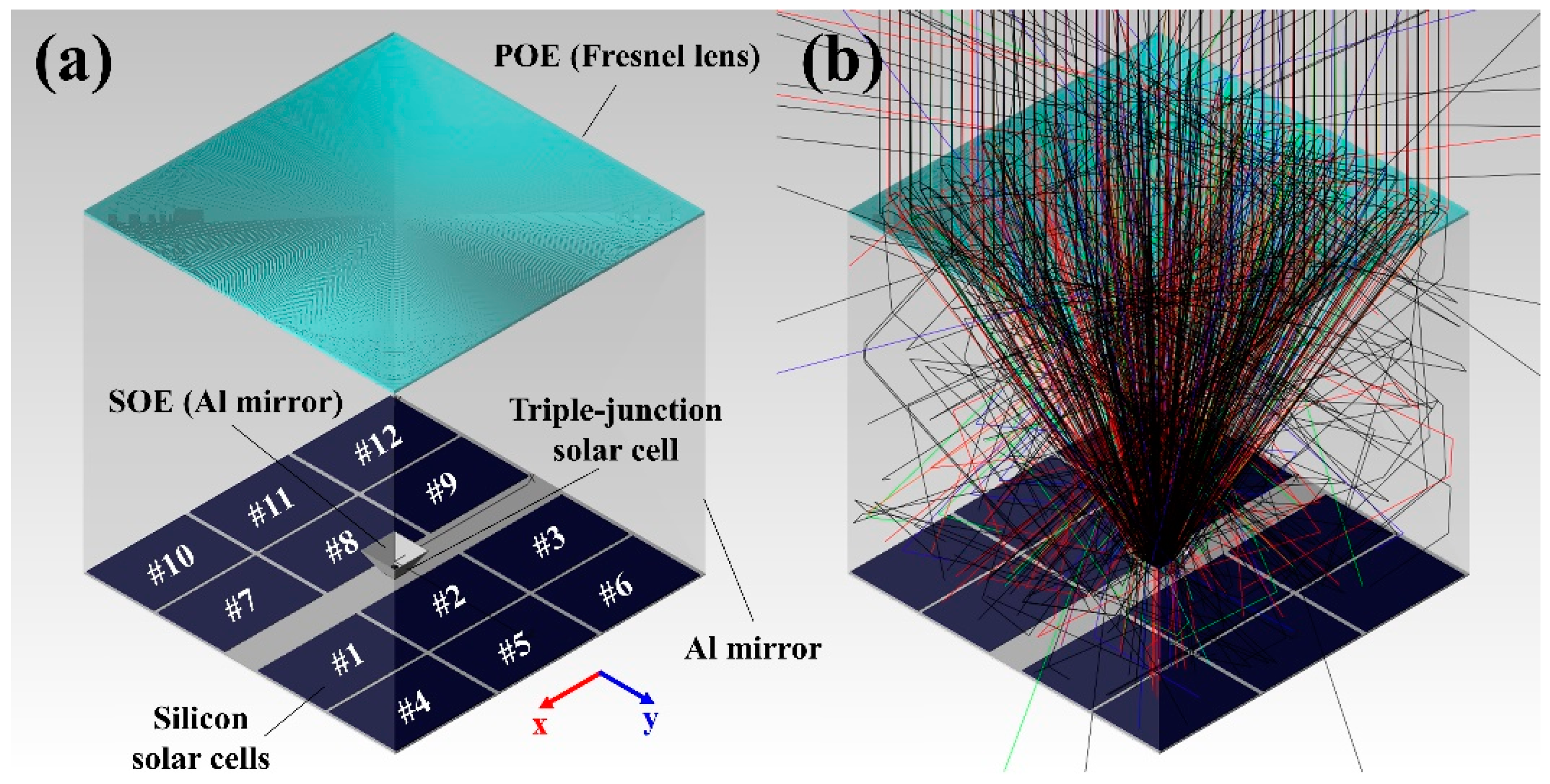
Figure 1. (a) The raytracing model and (b) raytracing results of the hybrid concentrator photovoltaic (CPV) module combined with low-cost silicon solar cells.
Applsci 10 02051 g001
Figure 2. Secondary optical element (SOE) designs at a 15 mm height with different mirror angles of (a) θ = 0°, (b) θ = 10°, (c) θ = 20°, (d) θ = 30°, (e) θ = 40°, and (f) θ = 50°.
Applsci 10 02051 g002
Figure 3. SOE designs with different mirror heights of (a) 0 mm (no SOE), (b) 5 mm, (c) 10 mm, (d) 15 mm, (e) 20 mm, and (f) 100 mm.
Applsci 10 02051 g003
Figure 4. Irradiance distributions of the six silicon solar cells for a pyramidal SOE with θ = 30° and h = 15 mm: (a) Si #1, (b) Si #2, (c) Si #3, (d) Si #4, (e) Si #5, and (f) Si #6. The size of each cell was 80 × 55 mm2.
Applsci 10 02051 g004
Figure 5. Irradiance distributions of the triple-junction and 12 silicon solar cells with three SOE configurations: (a,b) perpendicular (θ = 0°, h = 15 mm), (c,d) no SOE (h = 0), and (e,f) pyramidal (θ = 30°, h = 15 mm).
Applsci 10 02051 g005
Figure 6. Photographs of experimental measurement setup: (a) the solar simulator (WACOM, WXS-450S-65), (b) the CPV module with a Fresnel lens and a heat sink, (c) the perpendicular SOE (θ = 0°, h = 15 mm), (d) the pyramidal secondary optical element (SOE) (θ = 30°, h = 15 mm), (e) the laminated triple-junction solar cell with bypass diode, and (f) the polycrystalline silicon solar cell. Also shown are I-V and P-V curves of the (g) triple-junction solar cell and (h) silicon solar cells for the three SOE configurations.
Applsci 10 02051 g006
Table 1. Irradiance on the triple-junction and silicon solar cells of the hybrid concentrator photovoltaic (CPV) module with different mirror angles and a 15 mm height, as calculated using the TracePro raytracing software. We separated the results into the effective (0.3–1.299 μm) and lossy (1.3–2.5 μm) wavelength regions.
SOE AngleETJ,eff (W/m2)ETJ,loss (W/m2)ETJ,loss/ETJ,eff ratio (%)ESi,eff (W/m2)ESi,loss (W/m2)
0° (Perpendicular)326.87.22.2135.87.3
10°495.615.13.1130.67.1
20°588.624.14.1129.813.5
30°606.234.55.7127.49.9
40°604.741.76.9125.810.2
50°603.426.14.3125.15.2
Table 2. Irradiance on the triple-junction and silicon solar cells of the hybrid CPV module with different mirror heights, as calculated using TracePro. We again separated the results into the effective (0.3–1.299 μm) and lossy (1.3–2.5 μm) wavelength regions.
SOE Height (mm)ETJ,eff (W/m2)ETJ,loss (W/m2)ETJ, loss/ETJ,eff Ratio (%)ESi,eff (W/m2)ESi,loss (W/m2)
0 (No SOE)590.820.43.5131.27.1
5601.826.14.3131.59.8
10605.230.95.1130.310.4
15606.234.55.7127.49.9
20608.337.96.2124.89.3
100609.747.47.885.41.6
Table 3. Device characteristics of the triple-junction and 12 silicon solar cells of the hybrid CPV module, using three SOE configurations.
SOE ConfigurationCellPMAX (W/m2)VOC (V)ISC (A)Fill factorArea (cm2)
Perpendicular
(θ = 0°, h = 15 mm)
Triple-junction149.03.043.7883.61645.2
silicon5.67 (sum of #1–12)---645.2
No SOETriple-junction181.53.034.7381.8645.2
silicon5.99 (sum of #1–12)---645.2
Pyramidal
(θ = 30°, h = 15 mm)
Triple-junction212.83.045.5781.16645.2
silicon5.14 (sum of #1–12)---645.2