Abstract
A novel analytical solution for the designing of the birdcage RF coil has been demonstrated in this paper. A new concept of dominant resonance path has been introduced in this paper which is used to identify the specific closed current loop in the birdcage RF coil which is responsible for the dominant resonance frequency mode. This concept is used to determine the precise numerical values of the lumped capacitance deployed in the legs and/or end-rings of the birdcage RF coil for its proper operation at the desired resonance frequency. The analytical solution presented in this paper has been established by performing the two-port network based equivalent circuit modeling of the birdcage RF coil. The proposed analytical solution uses T-matrix theory and develops a relationship between the input impedance of the birdcage coil and the impedances of its leg and end-ring segments. The proposed analytical solution provides the information about the resonance frequency spectrum of the birdcage RF coil and solves the issue of its interfacing with external circuits without affecting its resonance characteristics. Based upon the proposed analysis and designing strategy presented in this paper, the low pass, high pass and band pass configurations of the birdcage RF coil were successfully implemented with FPCB (Flexible Printed Circuit board) technique for small volume NMR imaging applications at 1.5 T and 3.0 T MRI system. The results obtained for the implemented birdcage coils using the proposed analysis and designing technique are in closed agreement with already established methods.
1. Introduction
NMR imaging is highly in demand for the medical diagnostics and various other nonclinical and research applications due to its ability of providing very high-quality anatomical images non-invasively [1,2,3]. A highly sensitive and sophisticated radio frequency (RF) coil (or resonator) is responsible for obtaining these high-quality images only in a highly uniform magnetic field environment of an MRI system [4,5]. One such resonator is known as birdcage RF coil which is a popular choice for the nuclear magnetic resonance (NMR) based volume imaging for medical diagnostics [6]. Having the features like excellent magnetic field homogeneity, high signal-to-noise ratio, design flexibility and the ability to be designed for multi-resonance operation, the birdcage coil is a widely used RF resonator for whole volume NMR imaging applications at high as well as ultra-high field MRI systems [7,8,9,10,11,12,13].
The birdcage coil is a closed ladder network which is composed of identical cascaded segments of inductive and capacitive elements [14]. There exist multiple closed current loops in a birdcage coil which are responsible for the simultaneous existence of a definite number of resonance frequency signals. In general, a birdcage coil with N number of cascaded segments can be used to support maximum N/2 + 2 resonance frequency modes [15]. Several analytical and numerical solutions have been presented which explain the working of birdcage RF coil quite efficiently and provide the information about its resonance frequency spectrum [15,16,17,18,19,20]. Most of the existing solutions either involve some tedious techniques with complex mathematical formulation or limited to the determination of the resonance characteristics of the birdcage coil. However, in practical applications, it is required to connect the external circuits like impedance matching circuit (with the input/output ports) and detuning circuits (in the end-ring and/or leg segments) with the birdcage RF coil. This process can seriously affect its resonance frequency spectrum [9]. The existing methods however do not address this fundamental issue of external circuit interfacing with the birdcage coil.
In this paper, we have introduced a new concept of the dominant resonance path for the birdcage RF coil which is a simple and intuitive designing technique. The method works by identifying the closed current loop in the birdcage RF coil who is responsible of causing the dominant resonance frequency which is used for NMR imaging applications [21]. The proposed strategy provides rather convenient way to determine the lumped capacitances for the leg and end-ring segments of the birdcage RF coil for its proper operation at desired dominant resonance frequency. We have also devised a simple analytical solution for the birdcage RF coil by establishing it equivalent circuit model which is based upon the transmission matrix theory [21,22]. The proposed analytical solution provides the mathematical expression for the input impedance Zin of the birdcage RF coil as seen from the port in terms of the impedances of its leg and end-ring segments. Along with explaining the resonance frequency characteristics of the birdcage RF coil, the proposed analytical solution also provides the impedance at any desired position in the coil for the desired resonance frequency. This methodology solves the problems of external circuit interfacing with birdcage coil without disturbing its resonance characteristics.
The paper is divided into two main sections. The first section is about the analytical solution for the birdcage RF coil which explains the concept of dominant resonance path in the birdcage RF coil. It is then followed by a novel analytical solution which is derived using simple equivalent circuit modeling-and T-matrix theory. Second section is the design and analysis of the birdcage RF coil which contains the results (analytical, simulated and measured) of the successful implementation of the low pass, high pass and band pass configurations of the birdcage RF coil for small volume NMR imaging applications at 1.5 T and 3 T MRI systems by using the proposed analytical solution.
2. Analytical Solution for Birdcage RF Coil
2.1. Configuration of the Birdcage RF Coil
The line diagram of a conventional N-segments birdcage RF coil structure and the block diagram for its equivalent circuit model are shown in the Figure 1.
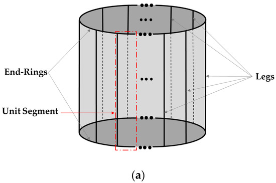
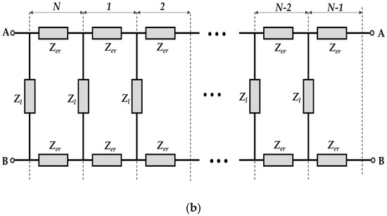
Figure 1.
N-segments birdcage RF coil: (a) Line diagram; (b) Block diagram of the equivalent circuit model.
A conventional birdcage RF is a three-dimensional cylindrical structure which is composed of N (even) number of segments which are connected to each other and are precisely arranged in the axial and azimuthal plans as shown in Figure 1a. The axial element of a segment is known as leg (or rung) which is connected to the conductor segments known as end-ring on both sides in the azimuthal planes. Each segment of a birdcage RF coil contains identical legs with impedance Zl and identical end-rings with impedance Zer as shown in Figure 1b. The impedances Zl and Zer are composed of inductive and capacitive elements with negligible resistance (practically less than 1 ohm). The inductive elements of a segment can be the cylindrical wires or the rectangular conductors (of finite thickness or thin foils). These are arranged in the axial and azimuthal planes. The capacitive elements in a segment are the lumped capacitors (with non-magnetic characteristics) which can be inserted in its leg or/and end-rings. Based on the capacitor position in a segment, three configurations of the birdcage RF coil can be realized. These are known as low pass (LP), high pass (HP), and band pass (BP) [14]. A single segment of each configuration is shown in Figure 2.
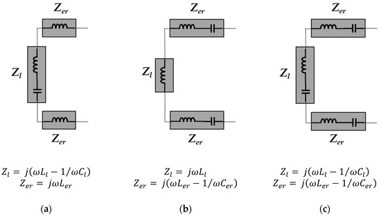
Figure 2.
Equivalent circuit diagrams of a single segment of the birdcage RF coil configurations: (a) Low pass (LP); (b) High pass (HP); (c) Band pass (BP).
Due to circular ladder structure with multiple cascaded identical segments, there does exist multiple resonance frequencies (some time referred as resonance modes) simultaneously in a conventional birdcage RF coil. The total number of these resonance frequencies mainly depend upon the number of legs (N), the inductances of leg (L1) and end-ring segment (L2), and the lumped capacitance in the leg (C1) and in the end-ring segment (C2). The first generalized analytic solution to determine the m possible resonance frequency modes (fm) of an N leg birdcage RF coil was developed by Hayes C.E. in 1985 with the aid of its equivalent circuit analysis is given in Equation (1) [14].
The above equation is although for a band pass configuration which however can be converted for low pass and high pass configurations by removing the terms containing C1 and C2 respectively. The numerical values of all possible resonance frequency modes of a birdcage coil obtained using Equation (1) are approximate as the terms L1 and L2 in Equation (1) represents the self-inductances of leg and end-ring segments. A more accurate but rather complex solution was provided by Jiaming J. in 1991 who also included the mutual inductance effect in the calculations of L1 and L2 [23].
2.2. Dominant Resonance Path
Basic principal behind the establishment of the birdcage coil was the development of a circular ladder structure which should be composed of the phase delay lines who can establish a unique phase pattern of the axial current on each coil leg [14]. The inductance (L) and capacitance (C) parameters of leg and end-ring segments are adjusted in such a manner that an ideal sinusoidal distribution of currents in terms of their intensities is realized on the legs of birdcage coil. An ideal sinusoidal intensity profile of currents along with their respective direction in different legs for the dominant resonance mode of an 8-leg birdcage RF coil is shown in Figure 3.
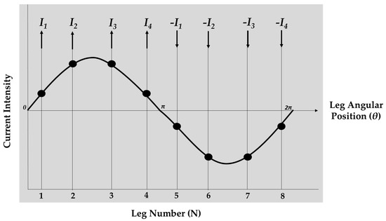
Figure 3.
Sinusoidal legs currents distribution on an 8-legs birdcage coil in dominant resonance mode.
This sinusoidal legs currents distribution is responsible of producing the homogeneous non-zero magnetic field everywhere inside the birdcage RF coil [24]. The resonance caused by this current distribution is known as the dominant resonance mode. The direction of currents in different legs of the birdcage RF coil as shown in Figure 3 provides the idea of the closed current loop which is responsible for the dominant resonance mode. The total path length of such closed current loop in the birdcage RF coil can be given by the following Equation (2).
where r is radius of the coil and l is the length of its leg. The above path length equation provides the information about the segments of the birdcage RF coil which are involved in the creation of the closed current loop whose resonance frequency is used for NMR imaging operation. A dominant resonance closed current loop consists of two coil legs which are joined by N/2 consecutive end-ring segments on each end-ring as shown in Figure 4a.
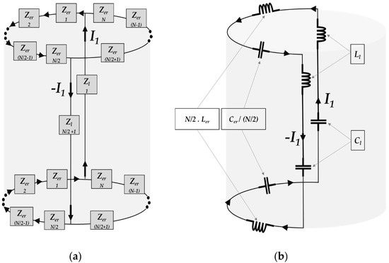
Figure 4.
A closed current loop in the birdcage RF coil representing: (a) The dominant resonance path; (b) Total lumped inductance and capacitance of end-rings and legs in the dominant resonance path.
There exists total N/2 closed current loops of path length P in birdcage RF coil. Any leg of the birdcage RF coil which is involved in the establishment of a closed current loop dose not involved in the other simultaneously existing N/2-1 closed current loops under dominant resonance condition. The desired dominant resonance mode required in the birdcage coil is the resonance of this closed current loop which can be determined as
where LT and CT are the total inductance and capacitance of the dominant resonance current loop. The total inductance LT is the sum of the inductances of two rungs and N end-ring segments which are connected in series as shown in Figure 4b. It can be given as follows.
Here the Ll and Ler are the total inductances of the legs and end-ring segments of a birdcage coil respectively. The numerical value of the self-inductance of a conductor with cylindrical or rectangular geometry can be determined by using the already established following relationships [23].
For a cylindrical conductor of length s and radius r,
For a rectangular strip conductor of length s and width w,
The total inductance LT of the dominant resonance loop for all three configurations of the birdcage RF coil which is determined by using Equation (4) remains unchanged. However, a single generalized equation cannot be established to determine the total capacitance CT of the dominant resonance loop for all three configurations of the birdcage coil. As for the low pass coil, capacitors are present only in the legs, for high pass only in the end rings while for the band pass in both locations, so the relationship to determine the total capacitance in each case can be given as follows,
The lumped capacitors required in the legs and end-rings of the low pass and high pass birdcage RF coil can easily be determined using Equations (8) and (9) respectively for the given coil dimensions and required resonance frequency. However, for the band pass birdcage coil, the end-ring capacitor value is usually needed to be assumed while the leg capacitor value is calculated using Equation (7). Moreover, there exist different combinations of leg and end-ring capacitors for the band pass birdcage coil and the one which causes more homogeneous magnetic field distribution is selected.
2.3. Equivalent Circuit Analysis
Most of the analytical solutions for the birdcage RF coil which are commonly developed by using the basic circuit analysis, transmission line theory, numerical electromagnetics or any other mathematical technique are limited to the determination of the resonance frequency modes only. However, the analytical solutions proposed in this paper provide a comprehensive mathematical formulation for the input port impedance in the leg or end-ring segment of the birdcage RF coil (regardless of its configuration) as a function of frequency. This is used to compute the numerical value of the impedance at any desired position for any desired frequency. This solves the problem of external circuit interfacing with the birdcage coil without effecting its resonance characteristics. The proposed method is based upon the determination of a single equivalent transmission matrix (Te-matrix) for the total equivalent circuit of the birdcage RF coil.
A conventional birdcage coil is an RF resonator which is composed of identical cascaded segments of inductive and capacitive elements. The conductor segments are the sources of inductance in the birdcage coil. The numerical value of the equivalent inductance (self and mutual) of the conductor segments with respect to its geometry (cylindrical wires or rectangular strips) which is determined by using mathematical equations is used as the lumped inductance [24]. While the lumped capacitors are the capacitive elements of the birdcage coil circuit. The block diagram of a unit segment of the birdcage RF coil consisting of the leg impedance Zl and the end-ring impedance Zer is shown in Figure 5a. The two ports equivalent circuit of the unit segment which is required to compute the T-matrix of the single segment of birdcage RF coil is also shown in Figure 5b.
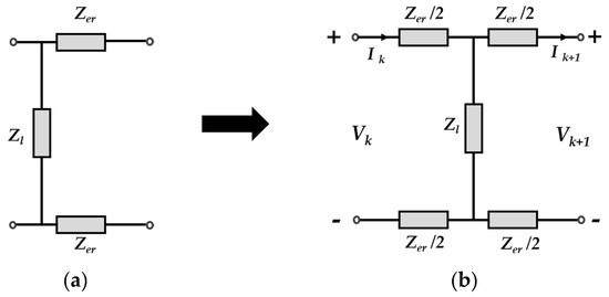
Figure 5.
The block diagrams of: (a) The unit segment of a conventional birdcage RF coil; (b) Two port equivalent circuit of the unit segment.
The impedance of leg segments Zl and the impedance of the end-ring segments Zer can be given as follows,
The input and output voltage and currents of the two-port network of Figure 5b can be related to each other via following matrix equation.
where T represents the transmission (ABCD) matrix of a unit segment of the birdcage RF coil that can be obtained by using the following matrix Equation (13).
In a conventional birdcage RF coil, N number of such identical segments as shown if Figure 5 are connected in cascade with each other. As the symmetry conditions prevail in this circuit, a single transmission matrix Te can be defined for the equivalent circuit of birdcage RF coil which can represent its overall transmission characteristics. However, the equivalent transmission matrix Te is a product of the N-1 identical transmission matrices T because the Nth segment (which can be chosen arbitrarily) of the birdcage RF coil is used to establish an interface with the receiver port of the MRI apparatus. Thus, its transmission matrix is not included in the computation of Te. The single equivalent transmission matrix Te can be expressed by Equation (14).
Since an arbitrary transmission matrix can be converted to a two-port network, the block diagram of the equivalent circuit of a birdcage RF coil containing two-port equivalent circuit model of the N−1 segments connected in cascade with the two-port equivalent circuit model of the Nth segment is shown in Figure 6.
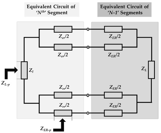
Figure 6.
Equivalent circuit model of N segments birdcage RF coil by converting each segment into a two-port network.
The equivalent circuit impedances Z ER and Z L can be determined by using the elements of the equivalent transmission matrix Te with the help of following Equations (15) and (16) respectively.
In a birdcage RF coil port can be established by interfacing the external circuit across any leg or end-ring segment but it exhibits the similar frequency characteristics. However, the port impedance as viewed from the external circuit would be different at both positions which results in different expressions for the general analytical solution. By considering the port connected across the end-ring segment Zer/2, the general analytical solution can be developed by calculating the equivalent impedance of the circuit model shown in Figure 6 as follows.
The final expression of the general analytical solution for the case when the port is created in the end-ring segment is given by the Equation (21).
In a similar way the general analytical solution for the case when the port is created in the leg segment can be derived and the final expression is given by the Equation (22).
The proposed method allows the input impedance to be obtained directly from the leg or end-ring of the birdcage RF coil. Precisely speaking, unlike the existing solutions for analyzing the relationship between the components values and the resonant frequency, the input impedance can be easily obtained at any point of the birdcage coil. Therefore, the method is not only useful to determine the resonance frequencies of the birdcage RF coil, but also to provide the port impedance which is an essential parameter to be known for interfacing any external circuitry like impedance matching circuit, detuning circuit etc. to the birdcage RF coil.
3. Design and Analysis of the Birdcage RF Coil
3.1. Design Based on Analytical Solution
Birdcage RF coils are designed in various sizes with respect to their length and diameter in according with the specified applications. The main tasks in the designing of a birdcage RF coil is the choice of coil configurations, number of legs, dimensions of legs and end-ring segments, lumped capacitance, and port impedance matching at desired resonance frequency. Legs and end-ring segments conductors are the sources of inductance in the birdcage coil. Their count and dimensions are the controlling factors of the magnetic field homogeneity as well as SAR inside the coil. While on the other hand, the lumped capacitors are responsible for producing the resonance at required radio frequency without effecting the magnetic field distribution. A balance between the conductor size and lumped capacitance value is quite necessary for an appropriate design of the birdcage RF coil. In order to validate the proposed analytical technique, we designed the low pass, high pass and band pass configurations of the linearly polarized birdcage RF coil for 1H NMR imaging in small volume applications at 1.5 T and 3 T MRI systems as shown in Figure 7.
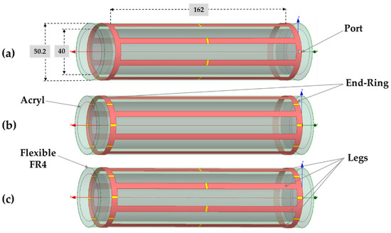
Figure 7.
Configurations of the birdcage RF coil for the reception of 1H NMR signal at 1.5 T and 3 T MRI systems: (a) Low pass; (b) high pass; (c) band pass. (All dimensions are in mm).
The designed birdcage RF coils are linearly polarized having 8 legs and 2 end-rings which are made of 35 µm thick and 5 mm wide rectangular copper strips etched on a flexible FR4 substrate (εr = 4.4) of 0.2 mm thickness. A 2 mm gap is created in the respective conductor segments of the legs and/or end-rings for SMT lumped capacitors. Total length of a single leg of the birdcage RF coil including capacitor gap is 162 mm. In order to keep the permanent 3D symmetry, the birdcage conductor pattern etched flexible FR4 was further attached on a solid acryl (εr = 3.2) cylinder of 5 mm thickness and 40 mm internal diameter. The length and diameter of the coil along with the dimension of the legs and end-rings segments are assumed to be constant for all three configurations of the 1.5 T and 3 T birdcage RF coils.
The self-inductance (referred as calculated inductance Lcal in this paper) of the leg and end-rings segments which is constant for all designed coils is determined using Equation (6). However, in the actual scenario there also exist very strong mutual inductance between the parallel conductor segments of the birdcage RF coil which affects the self-inductances of the coil. The self-inductance of the leg and end-ring segment which includes the effect of mutual-inductance was computed using the methods described by the birdcage builder [25]. This self-inductance is referred as effective inductance Leff in this paper. For the given dimensions of the birdcage RF coil the inductance Lcal and Leff for the leg and end-ring segment respectively are given in the Table 1 below.

Table 1.
Birdcage coil segments dimensions and inductances.
These calculated and effective inductance values were further used to compute the lumped capacitances required in the legs and/or end-rings for all three configurations of the birdcage RF coil at the desired frequencies of 63.8 MHz and 127.7 MHz (for 1.5 T and 3 T MRI systems respectively) by using the Equations (7)–(9). In order to prove the validity of the proposed method, we also computed the lumped capacitances for all three configurations by using the conventional method described by Equation (1), 2D circuit simulation and 3D electromagnetic simulation. The actual values of the lumped capacitance used in the implementation of the prototypes of low pass, high pass and band pass configurations of 1.5 T and 3 T birdcage RF coils were also measured. A comparison among lumped capacitor values determined through different techniques for 1.5 T and 3 T birdcage coils are given below in the Table 2 and Table 3 respectively.
Table 2.
Lumped capacitor values in pF for 1.5 T birdcage coils.
Table 3.
Lumped capacitor values in pF for 3 T birdcage coils.
The comparison provided in above Table 2 and Table 3 concludes that the numerical technique does only provide an approximate value of the lumped capacitor which is quite close to the actual value that is deployed in the prototype implementation. The measured capacitance value for the desired dominant resonance frequency is obtained by slightly tuning the numerically obtained capacitance. It is evident from the information provided in Table 2 and Table 3 that in comparison to the conventional methods, the effective lumped capacitance obtained through the proposed method exhibits least numerical error and requires lesser tuning to meet the desired resonance condition. Furthermore, the proposed analytic method described in this paper is quite simple and it does not require the hit and try method for capacitance computation which is commonly adopted in conventioanl 3D EM simulations. The results obtained through such analytical technique can directly be used in the coil implementation engineering which also includes the impedance matching operation at the desired resonance frequency.
3.2. Resonance Frequency
The proposed analytical solution given in Section 1 does also provide the information about the resonance frequency modes for all three configurations (low pass, high pass and band pass) of the birdcage RF coil by plotting its input impedance ZER_p against frequency. We assumed the case where the receiver port is connected across the half end-ring segment and then determined the resonance frequencies spectrum of all three coil configurations using Equation (21). The effective inductance values of the leg and end-ring segments along with their corresponding effective capacitance values (with respect to the coil configuration) were used to compute the impedances Zl and Zer. A comparison between the input impedance obtained though the analytical solution proposed in this paper and the input impedance plot obtained through 2D circuit simulation with effective inductance and their corresponding capacitance values in ANSYS [26] for each configuration of 1.5 T and 3 T birdcage RF coils are given in the Figure 8 below.
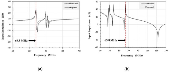
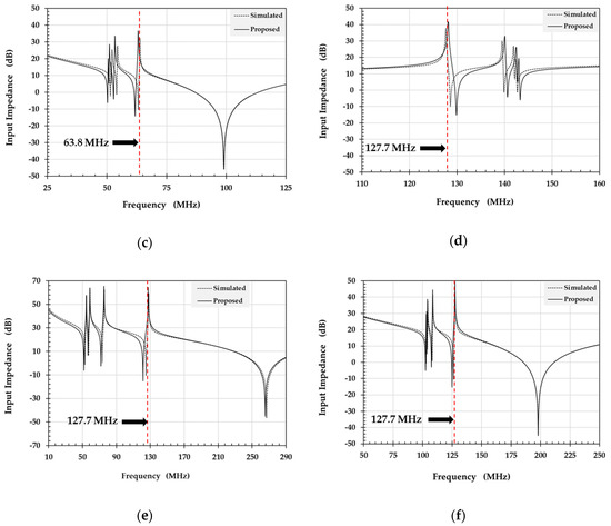
Figure 8.
Input impedance obtained using proposed analytical solution and conventional 2D simulation for the different configurations of the birdcage RF coil: (a) 1.5T low pass, (b) 1.5 T high pass, (c) 1.5 T band pass, (d) 3 T low pass, (e) 3 T high pass, (f) 3 T band pass.
3.3. Impedance Matching
It can be observed in all cases of Figure 8 that the pattern of variations in the input impedance (at the dominant resonance mode as well as the higher order resonance modes) provided by the proposed analytical solution does perfectly coincide with the one which was obtained using conventional 2D circuit simulation technique. The numerical values of the input impedance Zin at the desired resonance frequency is further used to design the impedance matching circuit which serves as an interface between the RF coil and receiver circuit. A conventional “L-matching” network with lumped (series) inductance and (parallel) capacitance can be used to accomplish this task. The input impedance Zin serves as the load impedance which is used to obtain the required values of the lumped components of the impedance matching network connected between the desired segment (end-ring in this case) of the birdcage RF coil and the 50 ohm port of the receiver. The numerical values of the input impedance ZER_p as obtained via proposed analytical solution along with the corresponding values of the lumped components of the matching circuit for all configurations of the designed 1.5 T and 3 T birdcage RF coils are provided in the Table 4.
Table 4.
Input impedance ZER_p of the designed birdcage RF coils at dominant resonance frequency and the corresponding lumped components of the matching circuit for 1.5 T and 3T MRI systems.
The reflection coefficient S11 which is a core parameter to explains the impedance matching of an RF circuit can easily be determined with the help of input impedance by using the following Equation (23).
A comparison between the reflection coefficients obtained by using the proposed analytical solution in the absence as well as presence of the impedance matching circuit for all configurations of the implemented 1.5 T and 3 T birdcage RF coils is provided in Figure 9.
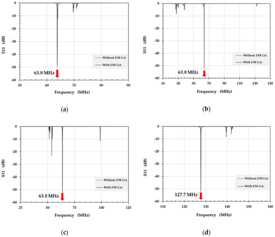
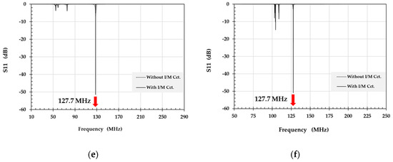
Figure 9.
Reflection coefficient S11 for the different configurations of the birdcage RF coil without and with impedance matching circuit: (a) 1.5 T low pass, (b) 1.5 T high pass, (c) 1.5 T band pass, (d) 3 T low pass, (e) 3 T high pass, (f) 3 T band pass.
3.4. Magnetic Field Homogeneity
Homogeneity of the magnetic field at the desired dominant resonance frequency (63.8 MHz for 1.5 T and 127.7 MHz for 3 T) everywhere inside the designed birdcage coils using the proposed analytical solution can be observed via 3D electromagnetic simulation. The simulation models of the birdcage RF coils were created in according with the dimensional information provided in Section 3.1 using 3D electromagnetic simulation software ANSYS HFSS [26]. The magnetic field distribution inside the coil under no load conditions (assuming air inside the coil) as determined in the transverse plans at different positions for each coil configuration is shown in Figure 10 below.
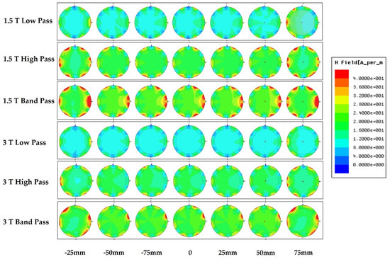
Figure 10.
Magnetic field distribution at dominant resonance frequency in transvers planes at various positions for all configurations of 1.5 T and 3 T birdcage RF coils.
It can be observed in Figure 10 above that each coil configuration causes quite homogeneous magnetic field distribution at the dominant resonance frequency while the bandpass configuration produces rather strong magnetic field than others for both 1.5 T and 3 T cases.
4. Conclusions
A simple technique for the designing and analysis of the birdcage RF coil based upon dominant resonance path and a novel analytical solution was demonstrated in this paper. We introduced a new concept of the dominant resonance path in the birdcage RF coil that identifies the specific closed current loop which is responsible of causing the dominant resonance frequency that is desired for NMR imaging. The concept is used to determine the numerical values of the lumped capacitances for the leg and/or end-ring segment of the birdcage RF coil using simple mathematical formulations. We also provided the analytical solutions for the birdcage RF coil in terms of its input impedance Zin by converting each of its section into a two-port network. The transmission parameters are used to determine the final analytical solution with the help of an equivalent Te matrix for the N-1 identical cascaded segments of the birdcage RF coil. Two separate analytical solution were developed by considering the feed port or external circuit location in the end-ring segment and leg segment. Both analytical solutions efficiently explain the characteristics of the birdcage RF coil, however the commonly used end-ring feed based analytical solution was mainly discussed in this paper. We implemented the birdcage RF coil in low pass, high pass and band pass configurations with FPCB etched conductor pattern technique for small volume NMR imaging applications at 1.5 T and 3.0 T MRI system. The numerical values of the lumped capacitance for the different configurations of the birdcage RF coil provided by the dominant resonance path method were found more accurate in comparison to those which were obtained through the conventional methods. The analysis of the implemented birdcage RF coils performed with the proposed analytical solution were also in complete agreement with the conventional methods.
Author Contributions
S.F.A. and H.D.K. conceived the idea, developed the analytical solution and carried out simulations. Y.C.K. designed the coils completed the experiments. B.-J.Y. developed the programming code for the implementation of the proposed analytical solution. H.D.K. analyzed the data and S.F.A. wrote the paper. All authors have read and agreed to the published version of the manuscript.
Funding
This research was financially supported by the Ministry of Trade, Industry, and Energy (MOTIE), Korea, under the “Regional industry based organization support program” (reference number R0004072) and the BK21 Plus project funded by the Ministry of Education (21A20131600011).
Conflicts of Interest
The authors declare no conflict of interest.
References
- Mansfield, P. Imaging by nuclear magnetic resonance. J. Phys. E Sci. Instrum. 1988, 21, 18. [Google Scholar] [CrossRef]
- Mallard, J.; Hutchison, J.M.; Edelstein, W.; Ling, R.; Foster, M. Imaging by nuclear magnetic resonance and its bio-medical implications. J. Biomed. Eng. 1979, 1, 153–160. [Google Scholar] [CrossRef]
- Blow, N. How to get ahead in imaging. Nature 2009, 458, 925–928. [Google Scholar] [CrossRef] [PubMed]
- Haase, A.; Odoj, F.; Kienlin, M.V.; Warnking, J.; Fidler, F.; Weisser, A.; Nittka, M.; Rommel, E.; Lanz, T.; Kalusche, B.; et al. NMR probeheads for in vivo applications. Concepts Magn. Reson. 2000, 12, 361–388. [Google Scholar] [CrossRef]
- Gruettrt, G.; Weisdorf, S.A.; Rajanayagan, V.; Terpsta, M.; Merkle, H.; Truwit, C.L.; Garwood, M.; Nyberg, S.L.; Uğurbil, K. Resolution improvements in in vivo 1H NMR spectra with increased magnetic field strength. J. Magn. Reson. 1998, 135, 260–264. [Google Scholar] [CrossRef]
- Hayes, C.E. The development of the birdcage resonator: A historical perspective. NMR Biomed. 2009, 22, 908–918. [Google Scholar] [CrossRef]
- Ahmad, S.F.; Kim, H.D. FPCB-based birdcage-type receiving coil sensor for small animal 1H 1.5T magnetic resonance imaging system. J. Sens. Sci. Technol. 2017, 26, 245–250. [Google Scholar]
- Yeung, D.; Hutchison, J.M.S.; Lurie, D.J. An efficient birdcage resonator at 2.5 MHz using a novel multilayer self-capacitance construction technique. MAGMA 1995, 3, 163–168. [Google Scholar] [CrossRef]
- Ahmad, S.F.; Kim, Y.C.; Choi, I.C.; Kim, H.D. Birdcage type NMR receiver coil sensor with integrated detuning circuit for 3T MRI system. In Proceedings of the IEEE SENSORS 2015, Busan, Korea, 1–4 November 2015; IEEE: Piscataway, NJ, USA, 2015; p. 2038. [Google Scholar]
- Solis, S.E.; Cuellar, G.; Wang, R.R.; Tomasi, D.; Rodriguez, A.O. Transceiver 4-leg birdcage for high field MRI: Knee imaging. Rev. Mex. Fis. 2008, 54, 215–221. [Google Scholar]
- Pimmel, P.; Briguet, A. A Hybrid Bird Cage Resonator for Sodium Observation at 4.7 T. Magn. Reason. Med. 1992, 24, 158–162. [Google Scholar] [CrossRef]
- Wang, C.; Li, Y.; Wu, B.; Xu, D.; Nelson, S.J.; Vigneron, D.B.; Zhang, X. A practical multinuclear transceiver volume coil for in-vivo MRI/MRS at 7T. Magn. Reason. Imaging 2012, 30, 78–84. [Google Scholar] [CrossRef]
- Bernard, J.D.; Shizhe, L.; Christopher, M.C.; Gerald, D.W.; Michael, B.S. A birdcage coil tuned by RF shielding for applications at 9.4T. J. Magn. Reason. 1998, 131, 32–38. [Google Scholar]
- Hayes, C.E.; Edelstein, W.A.; Schenk, J.F.; Muller, O.M.; Eash, M. An efficient, highly homogeneous radiofrequency coil for whole-body NMR imaging at 1.5 T. J. Magn. Reason. 1985, 63, 622–628. [Google Scholar] [CrossRef]
- Leifer, M.C. Resonant modes of birdcage coil. J. Magn. Reason. 1997, 124, 51–60. [Google Scholar] [CrossRef]
- Tropp, J. The Theory of the bird-cage resonator. J. Magn. Reason. 1989, 82, 51–62. [Google Scholar] [CrossRef]
- Tropp, J. The Theory of an arbitrarily perturbed bird-cage resonator and a simple method for restoring it to full symmetry. J. Magn. Reason. 1991, 95, 235–243. [Google Scholar] [CrossRef]
- Pascone, R.J.; Garcia, B.J.; Ftizgerald, T.M.; Vullo, T.; Zipagan, R.; Cahill, P.T. Generalized electrical analysis of low-pass and high-pass birdcage resonators. Magn. Reason. Imaging 1991, 9, 395–408. [Google Scholar] [CrossRef]
- Giovannetti, G.; Landini, L.; Santarelli, F.M.; Positano, V. A fast and accurate simulator for the design of birdcage coils in MRI. Magn. Reson. Mater. Phys. Biol. Med. 2002, 15, 36–44. [Google Scholar] [CrossRef] [PubMed]
- Novikov, A. Advanced theory of driven birdcage resonator with losses for biomedical magnetic resonance imaging and spectroscopy. Magn. Reason. Imaging 2011, 29, 260–271. [Google Scholar] [CrossRef] [PubMed][Green Version]
- Ahmad, S.F.; Kim, Y.C.; Choi, I.C.; Choi, S.W.; Kim, T.G.; Ahn, C.M.; Kim, H.D. Fast and efficient birdcage coil design process for high field MRI system by combining equivalent circuit model and 3D electromagnetic simulation. In Proceedings of the 2017 Asia Modelling Symposium (AMS), Kota Kinabalu, Malaysia, 4–6 December 2017; IEEE: Piscataway, NJ, USA, 2017; pp. 188–194. [Google Scholar]
- Kim, H.D. Analysis of the bird-cage receiver coil for MRI system employing a equivalent circuit model based on transmission matrix. J. Korea Multimed. Soc. 2017, 20, 1024–1029. [Google Scholar]
- Jianming, J. Analysis and design of RF coils. In Electromagnetic Analysis and Design in Magnetic Resonance Imaging, 1st ed.; CRC Press: Boca Raton, FL, USA, 1999; pp. 57–164. [Google Scholar]
- Mispelter, J.; Lupu, M. Homogeneous resonators for magnetic resonance: A review. C. R. Chim. 2008, 11, 340–355. [Google Scholar] [CrossRef]
- Chin, C.L.; Collins, C.M.; Li, S.; Dardzinski, B.J.; Smith, M.B. BirdcageBuilder: Design of specified-geometry birdcage coils with desired current pattern and resonant frequency. Concepts Magn. Reson. 2002, 15, 156–163. [Google Scholar] [CrossRef] [PubMed]
- ANSYS Electronics Desktop. Available online: http://www.ansys.com/products/electronics/ansys-electronics-desktop (accessed on 20 December 2019).


© 2020 by the authors. Licensee MDPI, Basel, Switzerland. This article is an open access article distributed under the terms and conditions of the Creative Commons Attribution (CC BY) license (http://creativecommons.org/licenses/by/4.0/).