Article

Design, Experiment, and Improvement of a Quasi-Zero-Stiffness Vibration Isolation System

1
Dongguan University of Technology, Dongguan 523808, China
2
State Key Laboratory of Robotics and System (HIT), Harbin 150001, China
3
Harbin Institute of Technology (Shenzhen), Shenzhen 518055, China
4
CRRC Qingdao Sifang Rolling Stock Co., Ltd., Qingdao 266111, China
5
Shenzhen Institutes of Advanced Technology, Chinese Academy of Sciences, Shenzhen 518055, China
*
Authors to whom correspondence should be addressed.
Appl. Sci. 2020, 10(7), 2273; https://doi.org/10.3390/app10072273
Submission received: 19 February 2020 / Revised: 12 March 2020 / Accepted: 14 March 2020 / Published: 27 March 2020
(This article belongs to the Section Mechanical Engineering)

Abstract

:
This paper proposes a new kind of quasi-zero-stiffness (QZS) isolation system that has the property of low-dynamic but high-static stiffness. The negative stiffness was produced using two magnetic rings, the magnetization of which is axial. First, the force–displacement characteristic of the two coupled magnetic rings was developed and the relationship between the parameters of the magnetic rings and the stiffness of the system was investigated. Then, the dynamic response of the QZS was analyzed. The force transmissibility of the system was calculated and the effects of the damping ratio and excitation amplitude on the isolation performance were investigated. The prototype of the QZS system was developed to verify the isolation effects of the system based on a comparison with a linear vibration isolation platform. Lastly, the improvement of the QZS system was conducted based on changing the heights of the ring magnets and designing a proper non-linear spring. The analysis shows the QZS system after improvement shows better isolation effects than that of the non-improved system.

1. Introduction

In many practical examples, an isolator usually shows the vibration isolation effect when the excitation frequency is over 2 times the natural frequency of the linear isolation system. The isolation frequency range will usually be expanded when the natural frequency of the isolator system is reduced, the cost of which is a reduction in the stiffness of the linear vibration isolation system, which causes an undesirably large static deflection [1,2]. To overcome this problem, nonlinear vibration isolation systems based on the quasi-zero-stiffness (QZS) have been investigated that have the properties of high-static and low-dynamic stiffness.
A QZS system has a localized zero stiffness in the equilibrium state that meets the requirement of a low natural frequency and a low static deformation at the same time. Numerous ways have been developed to realize a QZS system [3,4,5,6,7,8]. A typical form of QZS was designed by Carrella et al. [9], who proposed a simple QZS system consisting of a vertical spring acting in parallel with two oblique linear springs. The above-mentioned QZS system was improved by Kovacic et al. [10]. The oblique linear springs were replaced by two nonlinear pre-stressed oblique springs. It was found that the QZS system could produce a smaller dynamic stiffness in larger displacements near the equilibrium position, which helps to improve the performance of vibration isolation. In Ishida et al. [11], a vibration isolator, inspired by the origami-based foldable cylinders, was designed to serve as a nonlinear springs with a quasi-zero stiffness. Sun and Jing [12] proposed a three-direction isolation platform, which demonstrated the QZS property in three directions and achieved a much larger displacement range around the equilibrium position. The cam–roller–spring mechanism was designed to realize the negative stiffness spring of the QZS system [13]. In Vo and Le [14], a novel low-frequency isolation model was developed, where the nonlinear stiffness spring was realized by using a pneumatic cylinder through the mechanical structure of the wedge–roller–spring and cam–roller–spring mechanisms. Le and Ahn [15] designed a vibration isolation system for a vehicle seat that conformed to QZS theory. In Abbasi et al. [16], a vibration isolator with a high-static low-dynamic stiffness was constructed through a continuous rotating shaft, where such an isolator had the properties of linear damping and a cubic equivalent stiffness.
The mechanical structures with a negative stiffness are key components for the QZS system. In Carrella et al. [17], the QZS system is made up of three springs, two of which are to reduce the dynamic stiffness of the isolator. Lu et al. [18] proposed a two-stage isolation system with springs and two different definitions of the nonlinear transmissibility were compared. Some other kinds of springs have been investigated by researchers. Fulcher et al. [19] developed a kind of QZS system using buckled beams to generate a negative stiffness. Ishida et al. [20] presented a prototype vibration isolator based on a foldable cylinder with a torsional buckling pattern for the negative stiffness. Lan et al. [21] designed a special planar spring to manage a wide range of loads and the QZS system had a better vibration isolation performance compared with linear isolators. Sun et al. [22] proposed a 3D QZS system, where the negative stiffness spring was a pre-deformed, scissor-like structure, and the efficacy of a sensor system based on QZS was investigated. Kim et al. [23] developed a novel passive vibration isolator for an ultra-precision sensing system, utilizing a buckled plate spring with a ball joint. Naeeni et al. [24] investigated the application of QZS isolators in vibration pickups, a vibration pickups by using of vibration isolation principle of QZS, and the experimental results showed that the QZS isolator pickups has better performance than the linear isolator pickups even if there are physical and geometric errors. Besides, some achievements are obtained mainly focusing on control methodology based on the QZS isolation system [25].
Another way to construct a QZS system is to utilize magnets to construct springs with a negative stiffness. Carrella et al. [26] proposed a QZS system that consisted of two vertical mechanical springs and two magnets at the outer edge of each spring. The system could change the characteristics of the magnets to adapt to different working conditions to obtain the best vibration isolation performance. Wu et al. [27] and Sun et al. [28] proposed a novel spring with a negative stiffness that was composed of three cuboidal magnets. They found that the QZS system could reduce the vibration isolation frequency. Other systems with magnets used to create a negative spring were developed by Robertson et al. [29], Xu et al. [30], and Zhu et al. [31]. Since the magnets mentioned above had a significant spatial distribution and therefore not appropriate for compact situations, another kind of negative spring with magnets was proposed, where two magnetic rings are embedded in each other. In Mofidian and Bardaweel [32], a vibration system was analyzed, where the nonlinear negative stiffness was carried out using a combination of a magnetic spring and a mechanical oblique spring. The nonlinear damping was introduced to eliminate the undesired frequency jump phenomena. Zheng et al. [33] and Zhu et al. [34] developed prototypes of a QZS system with magnetic rings, the magnetization of which was along the radial direction. Since the axial magnetization had a high axial stiffness compared to the radial direction, this study investigated the effectiveness of a negative spring with magnetic rings, the magnetization of which was along the axial direction.
Furthermore, many methods have been proposed by researchers to improve the feasible load range and its effect on the frequency response performance. Inamoto and Ishida [35] developed a novel method for extending the load range of a vibration isolator using a foldable cylinder consisting of a torsional buckling pattern, where the experimental results show that the initial load range was extended by two to four times that of a conventional vibration isolator. Dao and Huang [36] developed a novel QZS vibration isolator by using flexure-based spring mechanisms, which enables itself to adjust the balance point according to the load weight. In addition, some adjustment methods have been proposed to improve the flexible load [37,38,39].
This paper proposes a new negative stiffness spring that uses magnets with an axial magnetization. The negative spring is made up of magnetic rings embedded in each other, which is proper for compacted situations compared to negative springs with mechanisms. Due to the high axial stiffness of magnets with an axial magnetization relative to the radial direction, the magnetic rings are magnetized along axial direction to withstand a greater load. First, the theoretical modeling of the negative stiffness spring was set up and the relationship between the force and displacement of the negative stiffness spring was studied using the equivalent magnetic charge method, thus obtaining the stiffness of the negative stiffness spring. The force–displacement and stiffness–displacement curves were obtained, which met the QZS theory based on finite element analysis. The experimental setup was developed to verify the effectiveness of the QZS system. Experiments with the linear isolation system corresponding to the QZS system were also undertaken. A comparison was made between the QZS system and the linear system regarding the vibration isolation performance. During the finite element modeling analysis, it was found that the axial magnetization magnetic ring’s stiffness–displacement characteristics could be used for positive stiffness spring optimization. The following improvements were made: choosing the appropriate parameters of the ring height to improve the negative stiffness spring and designing a suitable nonlinear spring that is parallel with the linear spring acting as a positive stiffness system. Finally, the improved QZS system had a better performance regarding transmissibility than the non-improved QZS system in theory.
The paper is organized as follows. In Section 2, the theoretical modeling of the QZS vibration isolation system is set up and the force–displacement characteristics of the two coupled magnet springs are developed. Then, the influence of the parameters of the coupled magnetic rings on stiffness is investigated. In Section 3, the dynamic response of the proposed QZS isolation system is analyzed. In Section 4, an experimental prototype is developed and experiments are conducted to verify the effectiveness of the QZS system. In Section 5, two methods for the improvement of the QZS system are discussed and the performance of the improved QZS system is analyzed and compared to a conventional system. Finally, some conclusions are given in Section 6.

2. The QZS Vibration Isolation System

The QZS vibration isolation platform is presented in Figure 1. It was constructed by using a negative stiffness spring with a positive stiffness spring in parallel, where the negative stiffness was produced by two axial-magnetized ring magnets.
As shown in Figure 1, the QZS vibration isolator was mainly composed of a linear spring, an inner ring magnet, and an outer ring magnet, an object. Furthermore, other subsidiary parts were used as well, which included intermediate shaft 1, intermediate shaft 2, linear motion bearing 1, linear motion bearing 2, and the adjustable screw nut. The two linear motion bearings guaranteed a straight-line movement of the platform and reduced the friction. The two intermediate shafts connected the positive stiffness spring and the negative stiffness spring in parallel, while an adjustable screw nut was used to regulate the relative displacement. All of the parts mentioned above made up the QZS vibration isolation system.

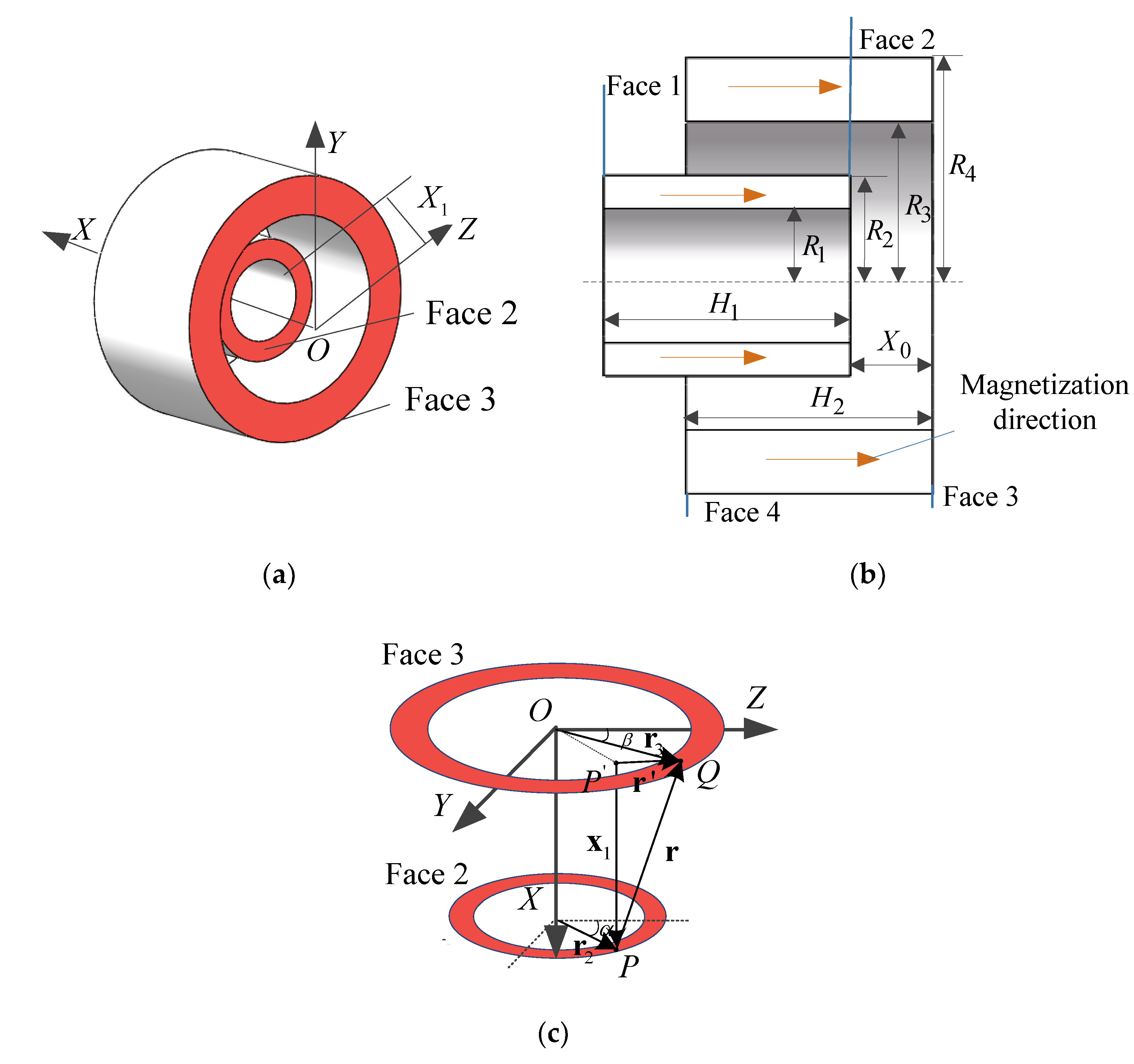
2.1. Force–Displacement Characteristic of the Two Coupled Magnet Springs

The configuration of the magnetic negative stiffness spring is shown in Figure 2. The magnetization directions of the inner and outer ring magnets are along the axial direction, as shown in Figure 2b.
To understand the force–displacement characteristics, faces 2 and face 3 are used here as an example to calculate the magnetic forces in the mathematical modeling [40]. The magnetic charge of the point P on face 2 of the inner ring magnet is q 2 :
q 2 = σ r 2 d α d r 2 ,
where r 2 and α are the polar coordinates of the point on the face 2 and σ is the surface density of magnetic charges of the ring magnets.
According to electromagnetic theory, the magnetic field intensity of point Q on face 3 of the outer ring magnet produced by point P is:
H = 1 4 π μ 0 q 2 r 2 r 0 ,
where μ 0 is the permeability of the vacuum, r is the distance between point P on face 2 and point Q on face 3, and r 0 = r / r is the unit vector between point P and point Q. Therefore, the magnetic field force at point Q is:
d F = H q 3 = H σ r 3 d β d r 3 = σ 2 4 π μ 0 r 2 r 3 d α d β d r 2 d r 3 r 3 r .
where r 3 and β are the polar coordinates of the point on face 3, and q 3 = σ r 3 d β d r 3 .
According to the static magnetism formula, the surface density of magnetism and the body density of magnetism can be given as:
{ σ = j n = μ 0 M n B = μ 0 ( H ¯ + M ) ,
where j is the intensity of the magnetic pole vector, n is the unit vector in the normal direction of the end face of the ring magnets, H ¯ is the electromagnetic intension force, and M is the intensity of magnetization.
Because no electric field is applied, H ¯ = 0 and B = μ 0 M . Due to the magnetization direction of the ring, the magnetism is parallel with the normal direction of the end face of the ring magnets. Therefore, Equation (4) can be given as:
σ = μ 0 M = B r ,
where B r is the residual magnetic flux density.
Then, Equation (3) can be expressed as:
d F = B r 2 4 π μ 0 r 2 r 3 d α d β d r 2 d r 3 r 3 r = C r 2 r 3 d α d β d r 2 d r 3 r 3 r ,
where C = B r 2 4 π μ 0 .
The magnetic field force in the x-direction at point Q on face 3 of the outer ring magnet produced by point P is:
d F 32 = C r 2 r 3 d α d β d r 2 d r 3 r 3 ri ,
where i is the unit vector in the x-direction.
The geometric relationship between point P and point Q from Figure 2 can be given as:
r = r x 1 = r 3 r 2 x 1 ,
where x 1 is the relative axial displacement of the inner ring magnet relative to the outer ring magnet.
Then:
ri = r 3 i r 2 i x 1 i ,
and
{ r 3 i = r 3 sin γ r 2 i = r 2 sin φ x 1 i = x 1 .
Therefore, Equation (9) can be simplified to:
ri = r 3 sin γ r 2 sin φ x 1 ,
where sin γ = x 1 r 3 2 + x 1 2 and sin φ = x 1 r 2 2 + x 1 2 .
Therefore, the distance between point P and point Q can be given as:
r = x 1 2 + ( r 3 cos β r 2 cos α ) 2 + ( r 3 sin β r 2 sin α ) 2 .
After substituting Equations (11) and (12) into Equation (7), the axial force produced by face 2 and face 3 is given as:
F 32 = C R 1 R 2 R 3 R 4 0 2 π 0 2 π ( r 3 sin γ r 2 sin φ x 1 ) r 2 r 3 d r 2 d r 3 d α d β [ x 1 2 + ( r 3 cos β r 2 cos α ) 2 + ( r 3 sin β r 2 sin α ) 2 ] 3 2 .
Then, the axial force produced by the other faces can be found in the same way:
F 31 = C R 1 R 2 R 3 R 4 0 2 π 0 2 π ( r 3 sin γ r 1 sin φ x 1 ) r 1 r 3 d r 1 d r 3 d α d β [ ( H 1 + x 1 ) 2 + ( r 3 cos β r 1 cos α ) 2 + ( r 3 sin β r 1 sin α ) 2 ] 3 2 ,
F 41 = C R 1 R 2 R 3 R 4 0 2 π 0 2 π ( r 4 sin γ r 1 sin φ x 1 ) r 1 r 4 d r 1 d r 4 d α d β [ x 1 2 + ( r 4 cos β r 1 cos α ) 2 + ( r 4 sin β r 1 sin α ) 2 ] 3 2 ,
F 42 = C R 1 R 2 R 3 R 4 0 2 π 0 2 π ( r 4 sin γ r 2 sin φ x 1 ) r 2 r 4 d r 2 d r 4 d α d β [ ( H 2 x 1 ) 2 + ( r 4 cos β r 2 cos α ) 2 + ( r 4 sin β r 2 sin α ) 2 ] 3 2 ,
where H 1 and H 2 are the heights of the inner and outer ring magnets; R 1 and R 2 are the inner and outer radii of the inner ring magnet; R 3 and R 4 are the inner and outer radii of the outer ring magnet.
The axial resultant force is a sum of the four forces and can be expressed as:
F = F 41 + F 32 F 31 F 42 .
In Equation (17), the positive sign means that the two faces have the same magnetic charge, and the negative sign means that the two faces have a different magnetic charge.
The negative stiffness can be found by differentiating Equation (17) with respect to the relative axial displacement x 1 between the inner ring magnet and the outer ring magnet:
K N = d F d x 1 .
The negative sign in Equation (18) shows that the restoring force produced by the magnetic spring is opposite to the magnetic force.

2.2. Analysis of the Stiffness of the Two Coupled Magnet Springs

Three main geometrical parameters affect the stiffness of the two coupled magnet springs: the height of the ring magnet, the radial gap between the inner ring magnet and outer ring magnet, and the radial thickness of the ring magnet.
As shown in Figure 3, when the radial gap between the two ring magnets increased while other geometrical parameters were invariable, the absolute value of the negative stiffness at the equilibrium position decreased and the curve became increasingly more uniform. However, if the absolute value of the negative stiffness at the equilibrium position was too small, the static deformation became too large and did not comply with the vibration isolation requirement.
The results of the negative stiffness for changing the radial thickness of the inner ring magnet are shown in Figure 4. It was found that the absolute value of the negative stiffness increased for the larger radial thickness and its nonlinearity increased.
The influence of the height of the ring magnets on the negative stiffness spring was divided into three cases for investigation. First, as shown in Figure 5a, when the height of the two ring magnets was the same, the difference in the absolute value of each curve at the equilibrium position and the nonlinearity variation near the equilibrium position was very small. Second, as shown in Figure 5b, with the increase of the height of the outer ring magnet, the absolute value of stiffness decreased, leading to the number of peaks changing from one to two and the distance between the two peaks becoming larger. The nonlinearity of the curve changed from strong to weak and then became strong in the process of increasing the height of the outer ring magnet. Finally, as shown in Figure 5c,d, if the difference in height of the two ring magnets was kept the same and the heights of the inner and outer ring magnets changed, the absolute value of the negative stiffness at the equilibrium position and the nonlinearity near the equilibrium position did not change a lot.

2.3. Stiffness of the QZS Vibration Isolation System

The QZS vibration isolation system was constructed using a negative stiffness spring with a positive stiffness spring in parallel, while the negative stiffness system of the QZS system was made of two ring magnets, as shown in Figure 6.
The dual magnetic stiffness was calculated using Equation (18), which was parallel to that of the linear positive stiffness spring. The force versus displacement and the stiffness versus displacement of the QZS system is shown in Figure 7. It can be observed that the stiffness at the equilibrium position was zero. Therefore the QZS system, which was composed of the ring magnets and linear spring, complied with the curve law of a general QZS system by adjusting the geometric parameters of the ring magnets and the linear spring stiffness.

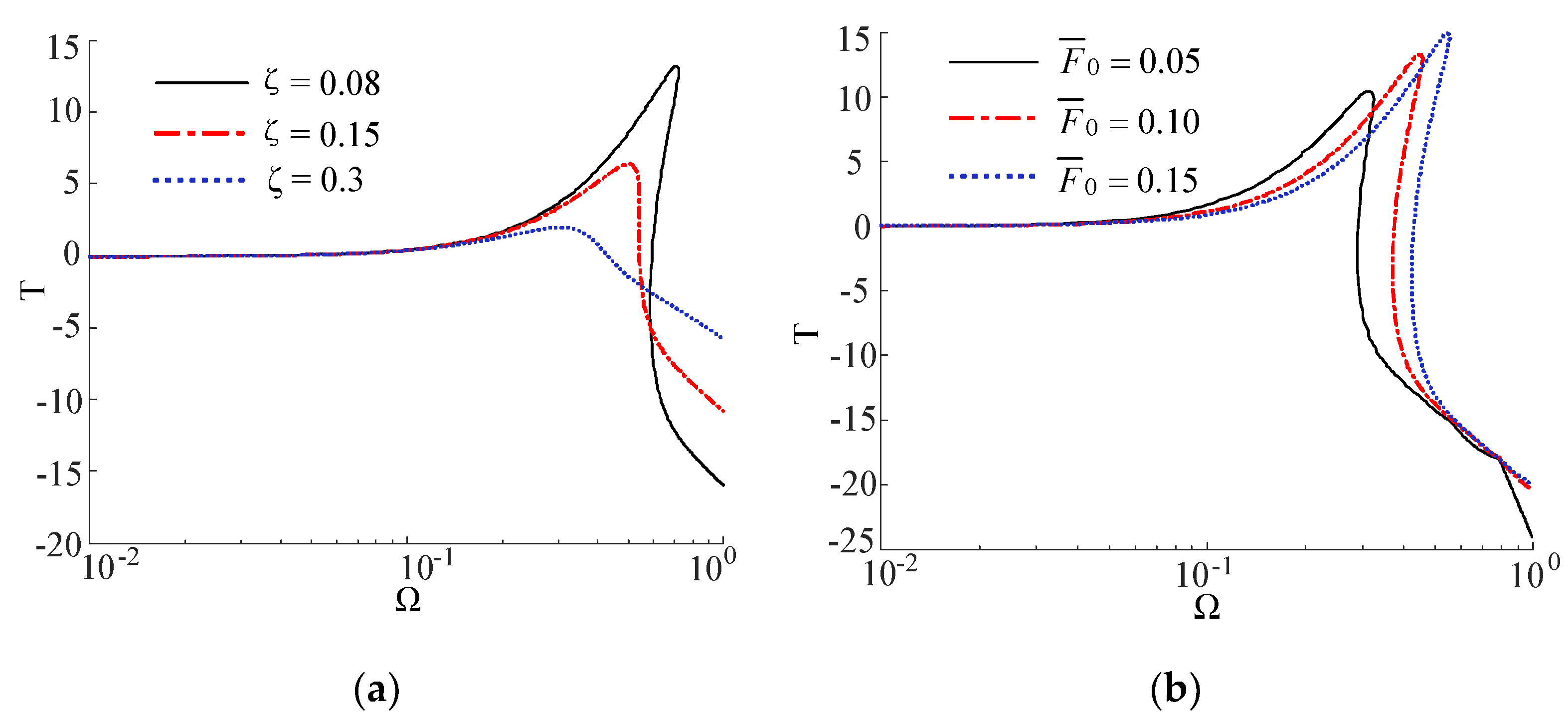
3. Dynamic Analysis of the QZS System

When considering the QZS dynamic response of the entire system, it is inconvenient to directly use Equation (18) for dynamic analysis; instead, a nonlinear curve should be fitted.
The equation of the force of the QZS of the vibration isolation system using the fitted curve can be expressed as Equation (19). The parameters γ 1 and γ 2 depict the nonlinearity of the force, and the force is as follows:
F Q Z S ( x ) = γ 1 x 3 + γ 2 x 5 .
Assuming that the exciting force is f = F 0 cos ( ω t + θ ) , the dynamic equation of the QZS system can be given as:
m y ¨ + c y ˙ + γ 1 y 3 + γ 2 y 5 = F 0 cos ( ω t + θ ) .
For the QZS system, Equation (20) can be written in a non-dimensional form as:
y ^ + 2 ξ y ^ + α y ^ 3 + β y ^ 5 = F ¯ 0 cos ( Ω τ + θ ) ,
where y ^ = y y s , Ω = ω ω n , τ = ω n t , ω n = k v m , ξ = c 2 m k v , α = γ 1 y s 2 k v , β = γ 2 y s 4 k v , F ¯ 0 = F 0 k v y s and y ^ = d y ^ d τ ; Note that y s is the static displacement of the linear spring and k v is the stiffness coefficient of the positive spring.
Assuming that the response of the whole system is y ^ = Y cos ( Ω τ ) and substituting it into Equation (21), the frequency–amplitude can be given as below based on the harmonic balance method:
( Y Ω 2 + 3 4 α Y 3 + 5 8 Y 5 ) + ( 2 ζ Y Ω ) 2 = F ¯ 0 2 .
Equation (22) can be solved to obtain:
Ω 1 , 2 = H Y 2 ξ 2 ± 1 Y 4 ξ 4 Y 2 4 ξ 2 H Y + F ¯ 0 2 .
where H 2 = 3 4 α Y 3 + 5 8 β Y 5 .
The non-dimensional form of the force transmitted through the QZS system and the simplified equation can be given as:
F ¯ 0 = 2 ξ y ^ ˙ + α y 3 + β y 5 2 ξ Y Ω sin Ω τ + H cos Ω τ = ( 2 ξ Y Ω ) 2 + H 2 cos ( Ω τ + ϕ ) ,
where t a n ϕ = 2 ξ Y Ω H .
The force transmissibility is given as:
T = F ¯ t F ¯ 0 = ( 2 ξ Y Ω ) 2 + H 2 F ¯ 0 .
As shown in Figure 8a, when the damping ratio was increased gradually, the phenomenon of the curve bending to the right was increasingly more inconspicuous and the strongest transmissibility was cut down, which means that the jump phenomenon became inconspicuous. Increasing the damping ratio was beneficial for reducing the initial frequency of vibration isolation as the jump-down frequency degraded in the process of increasing the damping ratio. However, the cost of increasing the damping ratio was that the force transmissibility became gradually larger in the high-frequency range of vibration isolation.
As shown in Figure 8b, the jump-down frequency and the force transmissibility were larger for the bigger excitation amplitudes, such that the initial frequency of vibration isolation did not meet the requirement of low-frequency vibration isolation. However, the influence of changing the excitation amplitude was not obvious in the high-frequency range of vibration isolation.

4. Experimental Setup and Results

4.1. Experimental Apparatus

An experimental prototype of the proposed QZS isolator shown in Figure 9a was developed to validate the vibration isolation performance. The entire experimental system consisted of an experimental prototype, an acceleration analyzer, a power amplifier, a shaking table, and a data acquisition analyzer. The experimental prototype contained an isolator and a mass. An acceleration sensor was mounted onto each of the shaking table and the mass, and the acceleration signals were transmitted to the data acquisition analyzer. The shaking table provided excitation movement for the prototype of the QZS isolator. Figure 9b depicts the scheme of the experimental system.
There were three main parts of the QZS experiment system. The first part was the excitation chain, which included the computer, the power amplifier, and the shaking table. The power amplifier received the signal about the frequency sweep range from the computer and transmitted the signal to the shaking table for movement. The second part was the QZS vibration isolation system, which included the isolation platform and the mass, as shown in Figure 1. The platform at the bottom of the isolator was rigidly connected to the shaking table using bolts. There were two linear motion bearings to ensure that the platform and the mass could have movement in the vertical direction. The third part was the signal acquisition system, which included two acceleration sensors (the acceleration type was EY2010, input range: ±10 g, full-scale accuracy: ±5%, work frequency: DC-2 kHz; YEC, Inc. Yangzhou, China ), data acquisition analyzer (the data acquisition analyzer type was Elite, input channels: 4, input voltage: 0–10 V, input frequency: 0–10 kHz, CMI, Inc. Beijing, China), and the analysis software was Elite (Version 1.3). An acceleration sensor was put on each of the mass and the shaking table. The data acquisition analyzer could receive the acceleration signals and transfer them to Elite to get the result of the experiment after analysis. The entire block diagram of the experiment can be seen in Figure 10.
This study conducted two different kinds of experiment: the experiment for the QZS isolation system, and the experiment for the corresponding linear vibration isolation system. A comparison was made between the results of the two different experiments. The corresponding linear vibration isolation platform was that of the QZS vibration isolation platform without the magnetic rings. The geometric parameters of the magnetic rings are shown in Table 1.
To verify the effectiveness of the QZS system, the dynamic test experiments were conducted for both the QZS system and the linear system. Then, the experiment used to detect the jump range of the QZS system was carried out.

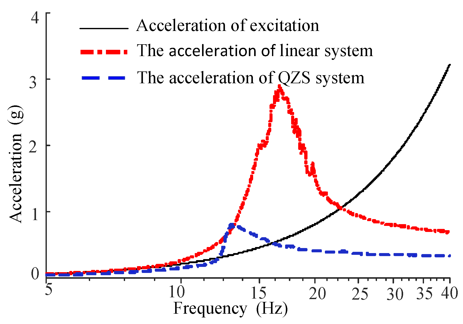
4.2. Experimental Results

From the experiment, the results of the acceleration of the QZS system and the linear system were obtained, as shown in Figure 11. The black line represents the acceleration of the excitation, the blue line is the acceleration of the mass of the QZS system, while the red line is that of the linear system.
As shown in Figure 11, the acceleration of the mass of the QZS system was always lower than that of the linear system, especially for the peak of these two different systems. The acceleration of the QZS system was lower than that of excitation in both the high-frequency and low-frequency ranges. In Figure 11, the frequency for the beginning of isolation of the linear system was about 24 Hz, while that of QZS system was 16 Hz, which shows the QZS vibration isolation platform had a wider frequency range for vibration isolation than its corresponding linear system and could achieve the low frequency for the initial vibration isolation.
Using the experimental data of the linear and QZS systems, the acceleration transmissibility in the frequency range 5–40 Hz was obtained, as shown in Figure 12. It can be seen that the peak of the transmissibility of the QZS system was 13.5 Hz, while that of the linear system was 16.5 Hz. Furthermore, the transmissibility of the QZS system was lower than that of the linear system. Therefore, it was concluded from the experiment that the QZS vibration isolation system had a better isolation performance than its corresponding linear system in the low-frequency range.
The QZS vibration isolator backward sweep experiment was carried out to verify the jump phenomena, as shown in Figure 13. It was found that the starting vibration isolation frequency of the forward sweep experiment was about 15 Hz, while the starting vibration isolation frequency of the backward sweep experiment was about 13.8 Hz. Therefore, the jump range was about 1.2 Hz.

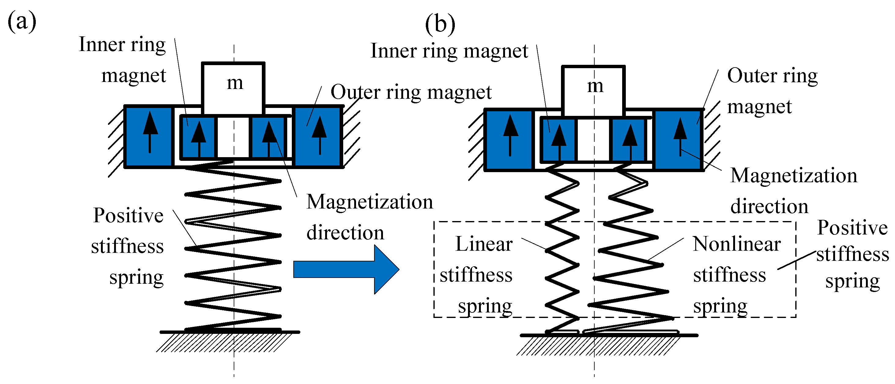
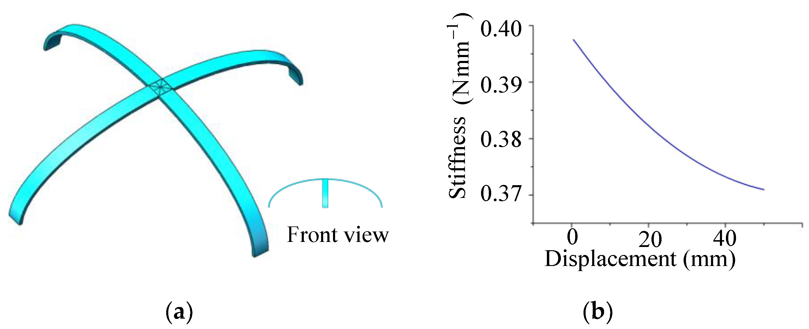
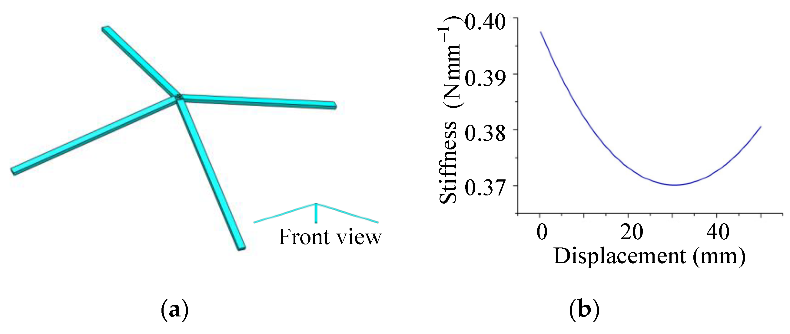
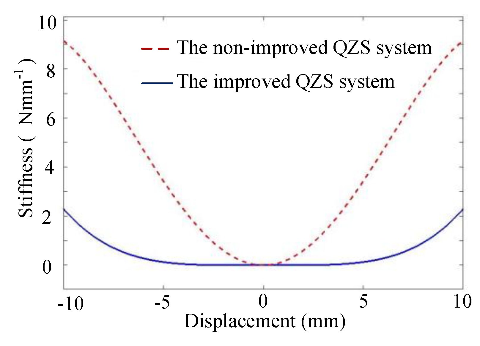
5. The Improvement of the QZS System

5.1. Ways to Improve Under a Wide Range of Loads

Based on the discussion in Section 2.2, it was found that the geometrical parameters of the magnetic spring affected the characteristics of the negative stiffness. For example, the height of the ring magnets affected the stiffness near the equilibrium position. As shown in Figure 5b, if the height of the inner ring magnet was kept constant and only the height of the outer ring magnet was increased, the number of peaks changed from 1 to 2 and the distance between the two peaks became increasingly larger. The nonlinearity of the curve changed from strong to weak and then became strong in the process of increasing the height of the outer ring magnet. Therefore, a practical way to improve the stiffness near the equilibrium position of the quasi-zero system was to change the height of the ring magnets, which enlarged the low stiffness range. This was the first method used for improvement.
Another method used for improvement was designing a nonlinear spring that was parallel with the linear spring to be the new positive stiffness system. The principle is shown in Figure 14. Here, flexible bars were used to design the nonlinear spring. The finite element software ANSYS 16.0 (ANSYS, Inc. USA)was used to investigate the effects of these parameters to find out how these geometrical parameters affected the nonlinear stiffness, and the structural stiffness of the flexible bars was comparatively studied in accordance with the calculation results of the plane beam element. Figure 15, Figure 16 and Figure 17 illustrate the different kinds of cross-section of bars that were used to construct the nonlinear spring.
As shown in Figure 15 and Figure 16, the nonlinear spring of the first two methods had certain soft spring properties. However, when it came to the QZS isolation system, the negative spring made the stiffness of the entire system unbalanced near the equilibrium position. In Figure 17, the curve of stiffness for the nonlinear spring went down, then up. It had the characteristic of symmetry near the 30 mm position, which depicted a better non-linear property. Therefore, a third nonlinear spring was adopted to improve the positive stiffness system and a displacement of 30 mm was used as the equilibrium position. This was the second method used for improvement.
Based on the improvement of the QZS isolation system, with the combination of the first method used for improvement by changing geometrical parameters of magnetic spring, and the second method used for improvement by using a non-linear spring as mentioned above, the result is shown in Figure 18. It can be seen that, after improvement, the stiffness in the interval −3 to 3 mm was very close to 0, which shows that the QZS after improvement had a better isolation performance for low frequencies with a small amplitude excitation.

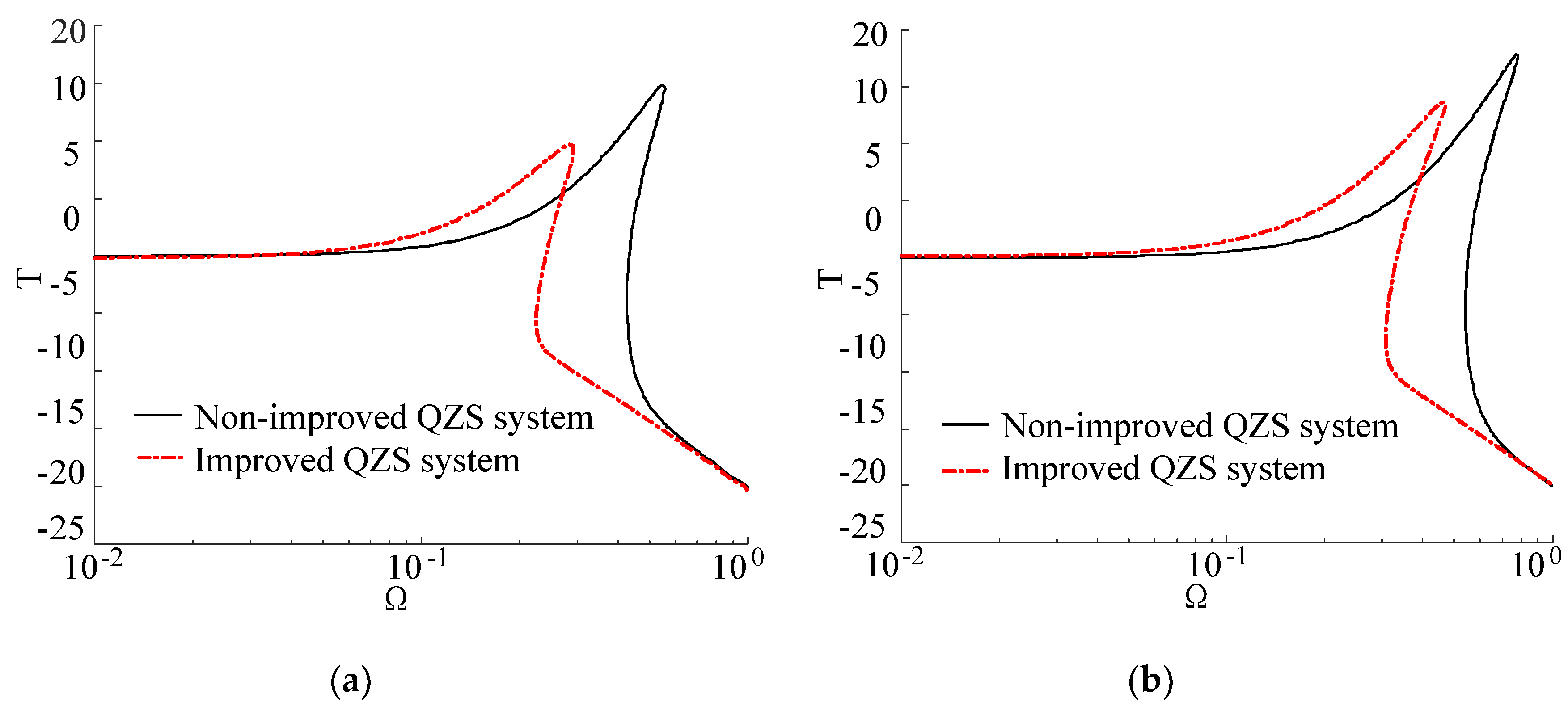
5.2. Dynamic Analysis for the Improved System

It can be seen from the previous analysis that the improved QZS system had a better isolation performance. In this part, the force transmissibility was the main consideration of the dynamic analysis.
From the study of Carrella et al. [16] on QZS’s transmissibility, the fitting stiffness equation of the improved QZS system can be given as:
K Q Z S = α 1 x 2 + α 2 x 4 .
For the QZS system, the dynamic equation of the system in a non-dimensional form can be given as:
y ^ + 2 ζ y ^ + χ 1 y ^ 3 + χ 2 y ^ 5 = F ¯ 0 cos ( Ω τ + θ ) ,
where y ^ = y y s , Ω = ω ω n , ω n = k v m , χ 1 = α 1 y s 2 3 k v , χ 2 = α 2 y s 4 5 k v and F ¯ 0 = F 0 k v y s ; y is the displacement of the mass; y s is the static displacement of the linear spring; k v is the stiffness coefficient of the positive spring; and F 0 is the exciting force.
According to the solution method used in Section 3, the force transmissibility of the improved system is defined as:
T = ( 2 ζ Y Ω ) 2 + H 2 F ¯ 0 ,
where H 2 = 3 4 χ 1 Y 3 + 5 8 χ 2 Y 5 and tan φ = 2 ζ Y Ω H ; it is assumed that the time domain response of the whole system is y ^ ( τ ) = Y cos ( Ω τ ) .
From Equation (28), the expression of the force transmissibility of the improved system was similar to that of the non-improved system, and they were all associated with the damping ratio and the excitation amplitude.
Comparisons between the non-improved and the improved force transmissibility with the different damping ratio can be seen in Figure 19. The fit coefficients of the improved QZS system were α 1 = 8.154 × 10 4 and α 2 = 2.389 × 10 4 , and the excitation amplitude was set to F ¯ 0 = 0.30 . It can be seen that when the damping ratio was ζ = 0.05 , the force transmissibility of the non-improved QZS system was bigger than that of the improved system in the latter half of the jumping range, but the jump-down frequency decreased. The result of the improvement was increasingly obvious when increasing the damping ratio. Figure 19 shows that after improvement, the peak of the force transmissibility and the jump-down frequency reduced significantly. Therefore, the improved quasi-zero-stiffness system had a better performance for low-frequency vibration isolation.
Figure 20 illustrates the comparison between the non-improved system and the improved system with the same excitation amplitude. The fit coefficients of the improved QZS system were α 1 = 8.154 × 10 4 and α 2 = 2.389 × 10 4 , and the damping ratio was set to ζ = 0.05 . When the amplitude of excitation was F ¯ 0 = 0.15 , the peak of the force transmissibility of the improved system was lower than that of the non-improved system and the jump-down frequency of the improved system was also lower than that of the non-improved system. With an increased excitation amplitude, the difference between the peaks of the two curves became increasingly small, but the jump-down frequency of the improved system was still lower than that of the non-improved system. It was concluded that the jump-down frequency of the improved system was always lower than that of the non-improved system and the difference between the peak of the non-improved and that of improved curves became smaller as the excitation amplitude became larger. Therefore, the improved system had a better vibration isolation performance for low-frequency amplitude excitation.

6. Discussions and Conclusions

This paper proposes a new kind of QZS system whose negative stiffness was produced using two magnetic rings with axial magnetization, where the negative spring of the magnetic rings was more suitable for compacted occasions and the axial direction for magnetization was more appropriate for greater loads compared to other directions of magnetization. The force–displacement characteristic of the two coupled magnetic rings was derived and the relationship between parameters of the magnetic rings and the stiffness of the system was studied, which provided the direction for the improvement of the system. The dynamic response of the QZS isolation system was analyzed, which showed that increasing the damping ratio was useful for the initial frequency of vibration isolation, but was not appropriate for high-frequency vibration isolation. An experimental prototype was developed to verify the vibration isolation ability of the QZS system. The results of the experiment showed that the proposed QZS system was better than that of a corresponding linear system at vibration isolation.
Two methods were proposed for the improvement of the QZS system: changing the axial heights of the magnetic rings and designing a nonlinear spring that was parallel with the linear spring. The dynamic response of the improved QZS system was analyzed. From this analysis, the force transmissibility of the improved system was lower than that of the non-improved system, which indicated that the effect of vibration isolation of the improved QZS system was better than that of the non-improved isolator.
Considering the improvement of the QZS system, whether by changing the axial stiffness of the magnetic ring or adopting a flexible nonlinear spring in combination with a linear spring, the QZS system displayed vibration isolation as long as the stiffness met the quasi-zero stiffness characteristics. For the QZS system, the wider the range of the zero-stiffness region at the balance point, the greater the vibration isolation ability. Furthermore, to improve the performance of the QZS system, many structures could be explored in the future for constructing the QZS system different from those schemes mentioned in this paper, which mainly focused on regulating the parameters of the nonlinear flexible structures or the axial stiffness of the magnetic ring.
It should be pointed out that the focuses of this paper were the proposed QZS system and how to improve its performance. Some other characteristics, such as stability, the effect of damping performance of the QZS system, the error of the mechanical system, and so on, could be explored in the future, which could be more complicated.

Author Contributions

S.W. and W.X. provided the conceptualization; S.W. designed experiments and wrote the manuscript; W.X. carried out experiments and analyzed experimental results; Y.N. was the director for the whole article, including the experiments and the structure of the article; B.L. proposed the new QZS system and provided the funding for the experiment; Y.H. provided project administration. All authors have read and agreed to the published version of the manuscript.

Funding

This work was supported by the National Key Research and Development Program of China (grant No. 2017YFB1302200) and the Joint Funds of the National Natural Science Foundation of China (grant no. U1613224). The work was also supported by Key Research and Development Program of Guangdong Province (grant no. 2019B090915001) and the KEY Laboratory of Robotics and Intelligent Equipment of Guangdong Regular Institutions of Higher Education (grant no. 2017KSYS009), and in part by the DGUT (Dongguan University of Technology)innovation center of robotics and intelligent equipment of China (grant no. KCYCXPT2017006) and the Shenzhen Research and Development Program of China (grant no. JSGG20180504170011639).

Acknowledgments

The authors appreciate Xiaozhi Qi for their help in the process of the dynamics simulations.

Conflicts of Interest

The authors declare no conflict of interest.

References

  1. Ibrahim, R.A. Recent advances in nonlinear passive vibration isolators. J. Sound Vibr. 2008, 314, 371–452. [Google Scholar] [CrossRef]
  2. Ledezma, R.D.F.; Tapia, G.P.E.; Ferguson, N.; Bennan, M.; Tang, B. Recent advances in shock vibration isolation: An overview and future possibilities. Appl. Mech. Rev. 2019, 71, 060802. [Google Scholar] [CrossRef]
  3. Ahn, H.J.; Lim, S.H.; Park, C. An integrated design of quasi-zero stiffness mechanism. J. Mech. Sci. Technol. 2016, 30, 1071–1075. [Google Scholar] [CrossRef]
  4. Valeev, A.; Tokarev, A.; Zotov, A. Material with quasi-zero stiffness for vibration isolation in civil and industrial structures and buildings. Int. IOP Conf. Ser: Earth Environ. Sci. 2019, 272, 032048. [Google Scholar] [CrossRef]
  5. Sorokin, V.N.; Kalashnikov, B.A.; Efimov, I.Y. Dynamics of anti-vibration mount with quasi-zero stiffness. Int. J. Mod. Phys. Conf. Ser. 2019, 1210, 012135. [Google Scholar] [CrossRef]
  6. Sadeghi, S.; Li, S. Harnessing the quasi-zero stiffness from fluidic origami for low frequency vibration isolation. In Proceedings of the ASME Conference on Smart Materials, Adaptive Structures and Intelligent Systems, Snowbird, UT, USA, 18–21 September 2017; pp. 3754–3763. [Google Scholar]
  7. Yan, L.; Gong, X. Experimental study of vibration isolation characteristics of a geometric anti-spring isolator. Appl. Sci. 2017, 7, 711. [Google Scholar] [CrossRef] [Green Version]
  8. Valeev, A. Vibration isolating plate with quasi-zero effect. Mater. Today Proc. 2018, 5, 688–692. [Google Scholar] [CrossRef]
  9. Carrella, A.; Brennan, M.J.; Waters, T.P. Static analysis of a passive vibration isolator with quasi-zero-stiffness characteristic. J. Sound Vibr. 2007, 301, 678–689. [Google Scholar] [CrossRef]
  10. Kovacic, I.; Brennan, M.J.; Waters, T.P. A study of a nonlinear vibration isolator with a quasi-zero stiffness characteristic. J. Sound Vibr. 2008, 315, 700–711. [Google Scholar] [CrossRef]
  11. Ishida, S.; Suzuki, K.; Shimosaka, H. Design and experimental analysis of origami-inspired vibration isolator with quasi-zero-stiffness characteristic. J. Vib. Acoust. Trans. ASM 2017, 139, 051004. [Google Scholar] [CrossRef]
  12. Sun, X.; Jing, X. Multi-direction vibration isolation with quasi-zero stiffness by employing geometrical nonlinearity. Mech. Syst. Signal Proc. 2015, 62–63, 149–163. [Google Scholar] [CrossRef]
  13. Wang, X.; Zhou, J.; Xu, D.; Ouyang, H.; Duan, Y. Force transmissibility of a two-stage vibration isolation system with quasi-zero stiffness. Nonlinear Dyn. 2017, 87, 633–646. [Google Scholar] [CrossRef]
  14. Vo, N.Y.P.; Le, T.D. Static Analysis of Low Frequency Isolation Model Using Pneumatic Cylinder with Auxiliary Chamber. Int. J. Precis. Eng. Manuf. 2020, 346, 1–17. [Google Scholar] [CrossRef]
  15. Le, T.D.; Ahn, K.K. A vibration isolation system in low frequency excitation region using negative stiffness structure for vehicle seat. J. Sound Vibr. 2011, 330, 6311–6335. [Google Scholar] [CrossRef]
  16. Abbasi, A.; Khadem, S.E.; Bab, S. Vibration control of a continuous rotating shaft employing high-static low-dynamic stiffness isolators. J. Vib. Control 2018, 24, 760–783. [Google Scholar] [CrossRef]
  17. Carrella, A.; Brennan, M.J.; Waters, T.P.; Jr, V.L. Force and displacement transmissibility of a nonlinear isolator with high-static-low-dynamic-stiffness. Int. J. Mech. Sci. 2012, 55, 22–29. [Google Scholar] [CrossRef]
  18. Lu, Z.; Brennan, M.J.; Chen, L.Q. On the transmissibility of nonlinear vibration isolation system. J Sound Vib. 2016, 375, 28–37. [Google Scholar] [CrossRef]
  19. Fulcher, B.A.; Shahan, D.W.; Haberman, M.R.; Seepersad, C.C.; Wilson, P.S. Analytical and experimental investigation of buckled beams as negative stiffness elements for passive vibration and shock isolation systems. J. Vib. Acoust. Trans. ASM 2014, 136, 031009. [Google Scholar] [CrossRef]
  20. Ishida, S.; Uchida, H.; Shimosaka, H.; Hagiwara, I. Design and numerical analysis of vibration isolators with quasi-zero-stiffness characteristics using bistable foldable structures. J. Vib. Acoust. Trans. ASM 2017, 139, 3. [Google Scholar] [CrossRef]
  21. Lan, C.C.; Yang, S.A.; Wu, Y.S. Design and experiment of a compact quasi-zero-stiffness isolator capable of a wide range of loads. J. Sound Vibr. 2014, 333, 4843–4858. [Google Scholar] [CrossRef]
  22. Sun, X.; Jing, X.; Cheng, L.; Xu, J. A 3-D quasi-zero-stiffness-based sensor system for absolute motion measurement and application in active vibration control. IEEE ASME Trans. Mechatron. 2015, 20, 254–262. [Google Scholar]
  23. Kim, J.; Jeon, Y.; Um, S.; Park, U.; Kim, K.S.; Kim, S. A novel passive quasi-zero stiffness isolator for ultra-precision measurement systems. Int. J. Precis. Eng. Manuf. 2019, 20, 1573–1580. [Google Scholar] [CrossRef]
  24. Naeeni, I.P.; Ghayour, M.; Keshavarzi, A.; Moslemi, A. Theoretical analysis of vibration pickups with quasi-zero-stiffness characteristic. Acta Mech. 2019, 230, 3205–3220. [Google Scholar] [CrossRef]
  25. Xu, J.; Sun, X. A multi-directional vibration isolator based on quasi-zero-stiffness structure and time-delayed active control. Int. J. Mech. Sci. 2015, 100, 126–135. [Google Scholar] [CrossRef]
  26. Carrella, A.; Brennan, M.J.; Waters, T.P.; Shin, K. On the design of a high-static–low-dynamic stiffness isolator using linear mechanical springs and magnets. J. Sound Vibr. 2008, 315, 712–720. [Google Scholar] [CrossRef]
  27. Wu, W.; Chen, X.; Shan, Y. Analysis and experiment of a vibration isolator using a novel magnetic spring with negative stiffness. J. Sound Vibr. 2014, 333, 2958–2970. [Google Scholar] [CrossRef]
  28. Sun, X.; Wang, F.; Xu, J. Analysis, design and experiment of continuous isolation structure with Local Quasi-Zero-Stiffness property by magnetic interaction. Int. J. Non-Linear Mech. 2019, 116, 289–301. [Google Scholar] [CrossRef]
  29. Robertson, W.S.; Kidner, M.R.F.; Cazzolato, B.S.; Zander, A.C. Theoretical design parameters for a quasi-zero stiffness magnetic spring for vibration isolation. J. Sound Vibr. 2009, 326, 88–103. [Google Scholar] [CrossRef]
  30. Xu, D.; Yu, Q.; Zhou, J.; Bishop, S.R. Theoretical and experimental analyses of a nonlinear magnetic vibration isolator with quasi-zero-stiffness characteristic. J. Sound Vibr. 2013, 332, 3377–3389. [Google Scholar] [CrossRef]
  31. Zhu, T.; Cazzolato, B.; Robertson, W.S.P.; Zander, A. Vibration isolation using six degree-of-freedom quasi-zero stiffness magnetic levitation. J. Sound Vibr. 2015, 358, 48–73. [Google Scholar] [CrossRef]
  32. Mofidian, S.M.; Bardaweel, H. Displacement transmissibility evaluation of vibration isolation system employing nonlinear-damping and nonlinear-stiffness elements. J. Vib. Control 2018, 24, 4247–4259. [Google Scholar] [CrossRef]
  33. Zheng, Y.; Zhang, X.; Luo, Y.; Yan, B.; Ma, C. Design and experiment of a high-static–low-dynamic stiffness isolator using a negative stiffness magnetic spring. J. Sound Vibr. 2016, 360, 31–52. [Google Scholar] [CrossRef]
  34. Zhu, Y.; Li, Q.; Xu, D.; Zhang, M. Modeling of axial magnetic force and stiffness of ring-shaped permanent-magnet passive vibration isolator and its vibration isolating experiment. IEEE Trans. Magn. 2012, 48, 2228–2238. [Google Scholar] [CrossRef]
  35. Inamoto, K.; Ishida, S. Improved feasible load range and its effect on the frequency response of origami-inspired vibration isolators with quasi-zero-stiffness characteristics. J. Vib. Acoust. Trans. ASM 2019, 141, 021004. [Google Scholar] [CrossRef]
  36. Dao, T.P.; Huang, S.C. A compact quasi-zero stiffness vibration isolator using flexure-based spring mechanisms capable of tunable stiffness. In Proceedings of the 18th International Conference on Applied Mechanics, London, UK, 25–26 August 2016; pp. 1572–1581. [Google Scholar]
  37. Kim, K.R.; You, Y.H.; Ahn, H.J. Optimal design of a QZS isolator using flexures for a wide range of payload. Int. J. Precis. Eng. Manuf. 2013, 14, 911–917. [Google Scholar] [CrossRef]
  38. Gatti, G. Statics and dynamics of a nonlinear oscillator with quasi-zero stiffness behaviour for large deflections. Commun. Nonlinear Sci. Numer. Simul. 2020, 83, 105143. [Google Scholar] [CrossRef]
  39. Ye, K.; Ji, J.C.; Brown, T. Design of a quasi-zero stiffness isolation system for supporting different loads. J. Sound Vibr. 2020, 115198. [Google Scholar] [CrossRef]
  40. Ravaud, R.; Lemarquand, G.; Lemarquand, V. Force and stiffness of passive magnetic bearings using permanent magnets, Part 1: Axial magnetization. IEEE Trans. Magn. 2009, 45, 2996–3002. [Google Scholar] [CrossRef] [Green Version]
Figure 1. Three-dimensional structure diagram of the proposed quasi-zero-stiffness (QZS) vibration isolator.
Applsci 10 02273 g001
Figure 2. The negative stiffness spring: (a) the negative spring system, (b) the cutaway view of the negative spring, and (c) the schematic for calculating the magnetic force.
Applsci 10 02273 g002
Figure 3. The influence of the radial gap.
Applsci 10 02273 g003
Figure 4. The influence of the radial thickness.
Applsci 10 02273 g004
Figure 5. The influence of the magnetic rings’ heights: (a) the stiffness when the height of H1 was equal to that of H2, (b) the stiffness when only H2 changed, and (c,d) the stiffness when the difference of height of the two ring magnetic rings was kept constant.
Applsci 10 02273 g005
Figure 6. The theoretical model of the QZS system.
Applsci 10 02273 g006
Figure 7. The force versus displacement and the stiffness versus displacement of the QZS system: (a) the relationship between the force and displacement of the QZS system, and (b) the relationship between the stiffness and displacement of the QZS system.
Applsci 10 02273 g007
Figure 8. The force transmissibility of the QZS system: (a) the transmissibility when ζ increased and (b) the transmissibility when F ¯ 0 increased.
Applsci 10 02273 g008
Figure 9. Experimental prototype and scheme for the QZS isolator system: (a) experimental prototype and (b) scheme of the experiment system.
Applsci 10 02273 g009
Figure 10. The block diagram of the experiment.
Applsci 10 02273 g010
Figure 11. The comparison between the linear system and the QZS system.
Applsci 10 02273 g011
Figure 12. The transmissibility comparison between the two systems.
Applsci 10 02273 g012
Figure 13. The jumping phenomenon of the QZS system.
Applsci 10 02273 g013
Figure 14. The second way to improve the QZS system: (a) the original QZS system and (b) the improved QZS system.
Applsci 10 02273 g014
Figure 15. The shape of the cross-section was round: (a) the shape of a nonlinear spring and (b) the stiffness of the nonlinear spring for finite element analysis.
Applsci 10 02273 g015
Figure 16. The shape of the cross-section was a rectangle: (a) the shape of a nonlinear spring and (b) the stiffness of the nonlinear spring for finite element analysis.
Applsci 10 02273 g016
Figure 17. The shape of the cross-section was a rectangle: (a) the shape of a nonlinear spring and (b) the stiffness of the nonlinear spring for finite element analysis.
Applsci 10 02273 g017
Figure 18. The comparison between the non-improved system and the improved QZS system regarding the stiffness–displacement characteristic.
Applsci 10 02273 g018
Figure 19. The force transmissibility comparison between the non-improved system and the improved system with the same damping ratio: (a) ζ = 0.05 and (b) ζ = 0.10.
Applsci 10 02273 g019
Figure 20. The comparison between the non-improved system and the improved system with the same excitation amplitude: (a) F ¯ 0 = 0.15 and (b) F ¯ 0 = 0.30 .
Applsci 10 02273 g020
Table 1. The main geometric parameters of the vibration isolation platform.
ParametersValue
The inner diameter of the inner magnetic ring D110 mm
The outer diameter of the inner magnetic ring D230 mm
The inner diameter of the outer magnetic ring D360 mm
The outer diameter of the outer magnetic ring D480 mm
Remanence B r 1.24 T
The stiffness of the linear spring7500 N/m

