The FEM Model of the Pump Made of Dielectric Electroactive Polymer Membrane


Abstract
:1. Introduction
2. Principle of Operation of DEAP Actuator
3. Experiments
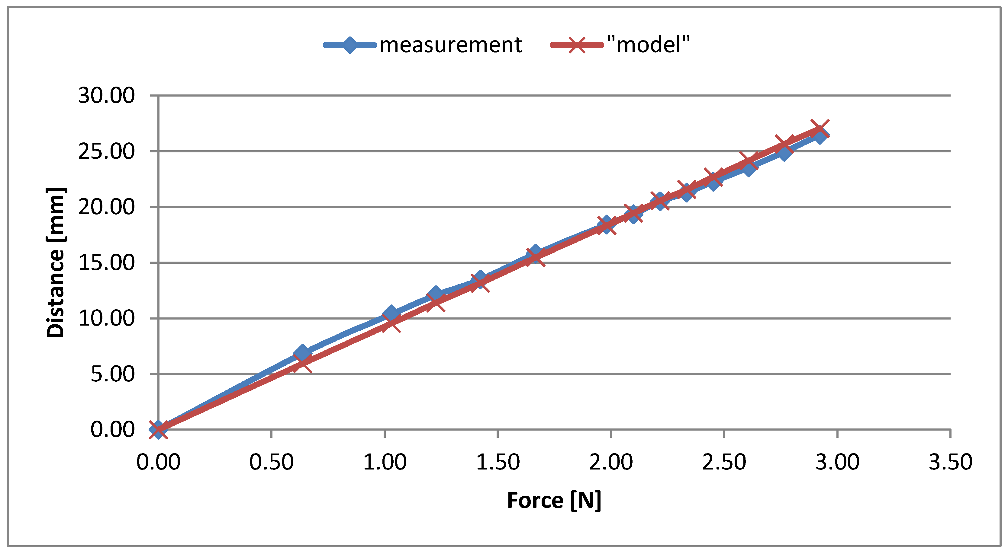
3.1. Static Characteristics
3.2. The Identification Process
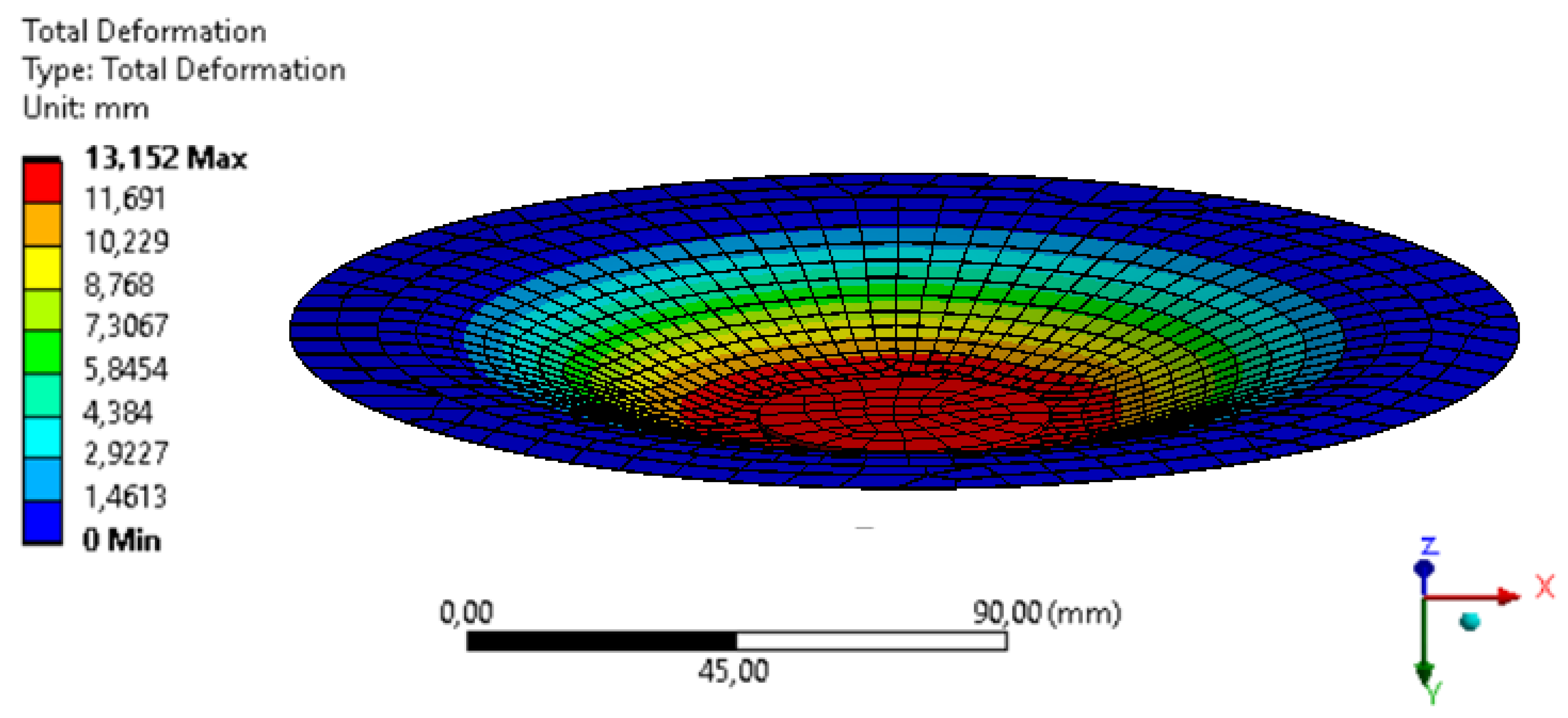
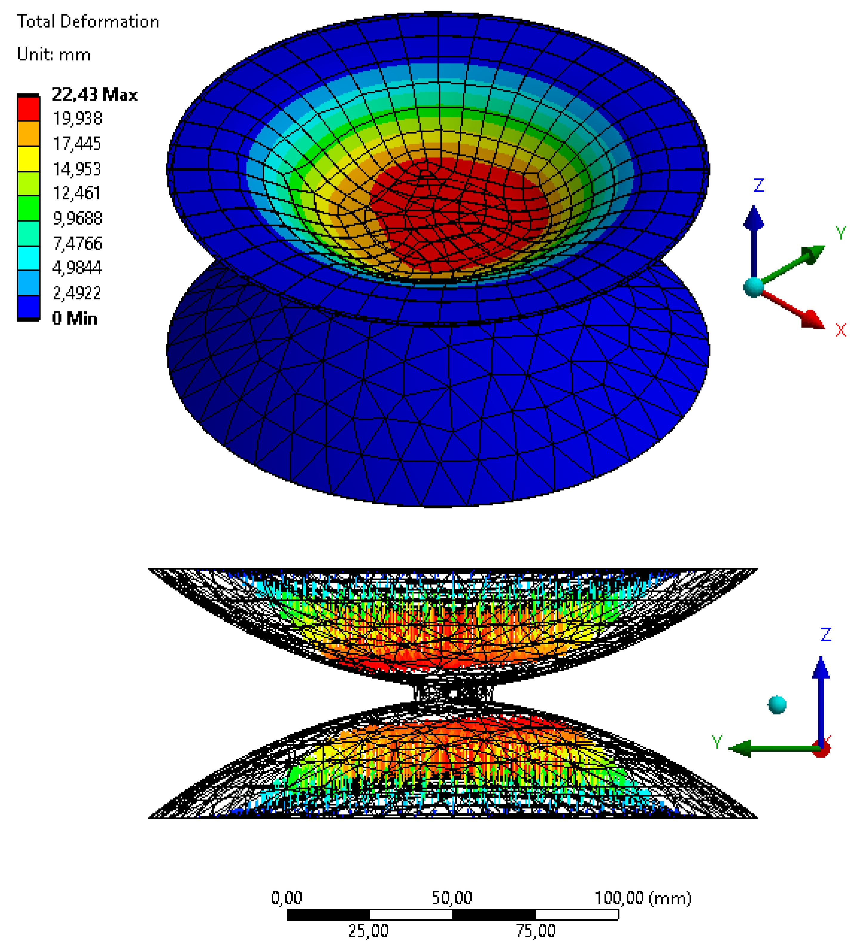
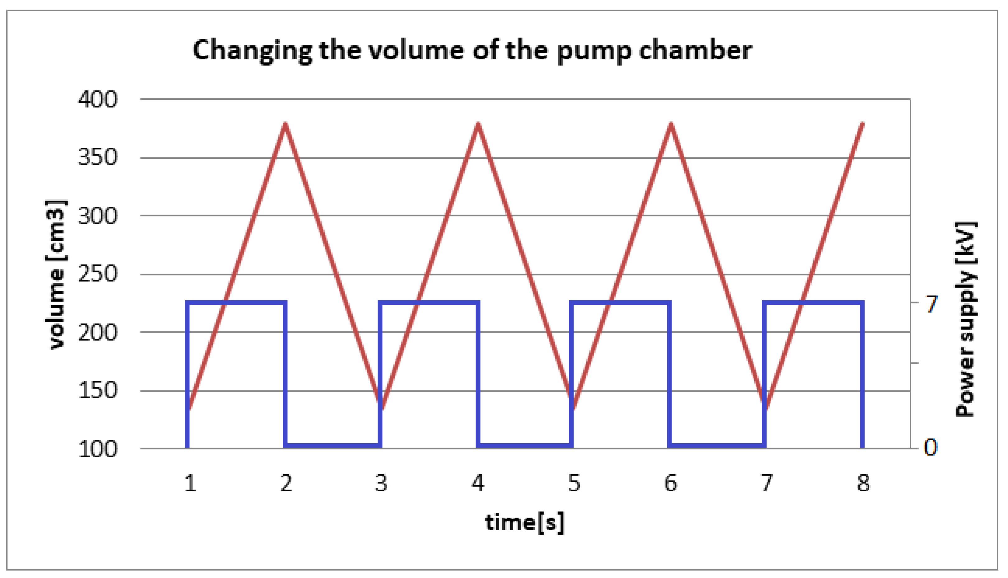
4. Pump FEM Model with DEAP Membrane
5. Conclusions
Funding
Conflicts of Interest
References
- Kim, K.J.; Tadokoro, S. Electroactive Polymers for Robotics Applications: Artifical Muscles and Sensors; Springer: London, UK, 2007. [Google Scholar] [CrossRef]
- Bar-Cohen, Y. Electroactive Polymer (EAP) Actuators as Artificial Muscles: Reality, Potential, and Challenges; SPIE Press: Bellingham, DC, USA, 2001. [Google Scholar]
- Carpi, F.; Anderson, I.; Bauer, S.; Frediani, G.; Gallone, G.; Gei, M.; Graaf, C.; Jean-Mistral, C.; Kaal, W.; Kofod, G.; et al. Standards for dielectric elastomer transducers. Smart Mater. Struct. 2015, 24. [Google Scholar] [CrossRef] [Green Version]
- Berselli, G.; Vertechy, R.; Babi, M.; Castelli, V.P. Dynamic modeling and experimental evaluation of a constant-force dielectric elastomer actuator. J. Intell. Mater. Syst. Struct. 2013, 24, 779–791. [Google Scholar] [CrossRef]
- Rosenblatt, F.; Morrison, J.F.; Iannuci, L. Modelling Electroactive Polymer (EAP) Actuators: Electro-Mechanical Coupling using Finite Element Software. In Proceedings of the SPIE Smart Structures and Materials + Nondestructive Evaluation and Health Monitoring, San Diego, CA, USA, 9–13 March 2008. [Google Scholar] [CrossRef]
- Wissler, M.; Mazza, E. Electromechanical Coupling in Dielectric Elastomer Actuators. Sens. Actuators A Phys. 2007, 138, 384–393. [Google Scholar] [CrossRef]
- He, T.; Zhao, X.; Suo, Z. Dielectric elastomer membranes undergoing inhomogeneous deformation. J. Appl. Phys. 2009, 106. [Google Scholar] [CrossRef] [Green Version]
- Wang, S.; Decker, M.; Henann, D.L.; Chester, S.A. Modeling of dielectric viscoelastomers with application to electromechanical instabilities. J. Mech. Phys. Solids 2016, 95, 213–229. [Google Scholar] [CrossRef] [Green Version]
- Li, Y.; Oh, I.; Chen, J.; Zhang, H.; Hu, Y. Nonlinear dynamic analysis and active control of visco-hyperelastic dielectric elastomer membrane. Int. J. Solids Struct. 2018. [Google Scholar] [CrossRef]
- Rosset, S.; Araromi, O.A.; Schlatter, S.; Shea, H. Fabrication process of silicone-based dielectric elastomer actuators. J. Vis. Exp. 2016, 108, 1–13. [Google Scholar] [CrossRef] [PubMed] [Green Version]
- Rizzello, G.; Naso, D.; York, A.; Seelecke, S. Modeling, identification, and control of a dielectric electro-active polymer positioning system. IEEE Trans. Control. Syst. Technol. 2015, 23, 632–643. [Google Scholar] [CrossRef]
- Wang, Z.; He, T. Electro-viscoelastic behaviors of circular dielectric elastomer membrane actuator containing concentric rigid inclusion. Appl. Math. Mech. 2018, 39, 547–560. [Google Scholar] [CrossRef]
- De Saint-Aubin, C.; Rosset, S.; Schlatter, S.; Shea, H. High-cycle electromechanical aging of dielectric elastomer actuators with carbon-based electrodes. Smart Mater. Struct. 2018, 27. [Google Scholar] [CrossRef]
- Hodgins, M.; Rizzello, G.; York, A.; Seelecke, S. High-frequency dynamic model of a pre-loaded circular dielectric electro-active polymer actuator. In Proceedings of the ASME 2013 Conference on Smart Materials, Adaptive Structures and Intelligent Systems, Snowbird, UT, USA, 16–18 September 2013. [Google Scholar] [CrossRef]
- Bernat, J.; Kołota, J. Adaptive Controller with Output Feedback for Dielectric Electro-Active Polymer Actuator. In Proceedings of the 12th International Workshop on Robot. Motion and Control (RoMoCo’19), Poznań, Poland, 8–10 July 2019; pp. 247–251. [Google Scholar] [CrossRef]
- Bernat, J.; Kołota, J. Adaptive Observer for State and Load Force Estimation for Dielectric Electro-Active Polymer Actuator. In Proceedings of the 11th IFAC Symposium on Nonlinear Control Systems NOLCOS 2019, Vienna, Austria, 4–6 September 2019. [Google Scholar]
- Ravaud, R.; Lemarquand, G.; Babic, S.; Lemarquand, V.; Akyel, C. Cylindrical Magnets and Coils: Fields, Forces, and Inductances. IEEE Trans. Magn. 2010, 46, 3585–3590. [Google Scholar] [CrossRef]
- Vokoun, D.; Beleggia, M.; Heller, L.; Sittner, P. Magnetostatic interactions and forces between cylindrical permanent magnets. J. Magn. Magn. Mater. 2009, 21, 3758–3763. [Google Scholar] [CrossRef]
- Kaal, W.; Herold, S. Electroactive polymer actuators in dynamic applications. IEEE/ASME Trans. Mechatron. 2011, 16, 24–32. [Google Scholar] [CrossRef]
- Anderson, I.; Gisby, T.; McKay, T.; O’Brien, B.; Calius, E. Multifunctional dielectric elastomer artificial muscles for soft and smart machines. J. Appl. Phys. 2012, 112. [Google Scholar] [CrossRef]


| Parameter | Symbol | Value | Unit |
|---|---|---|---|
| mass | m | 125 | g |
| standard gravity | g | 9.81 | m/s2 |
| vacuum permittivity | ε0 | 8.85*10−12 | F/m |
| relative permittivity | εr | 8.73 | - |
| coefficient of viscoelasticity | ke | 3.11 | MPa |
| coefficient of viscoelasticity | ηe | 13.4 | MPa·s |
| damping coefficients | b | 1.45 | Nms |
| Ogden model coefficients | β1 | 11.4 | kPa |
| Ogden model coefficients | β2 | 50.3 | kPa |
| Ogden model coefficients | β3 | 44.1 | kPa |
| Ogden model coefficients | γ1 | −118 | kPa |
| Ogden model coefficients | γ2 | −30.4 | kPa |
| Ogden model coefficients | γ3 | 23.3 | kPa |
| Parameter | Symbol | Value | Unit |
|---|---|---|---|
| Pre-stretch tape diameter | - | 94 | mm |
| Post-stretch tape diameter 2 | - | 210 | mm |
| Pre-stretch tape thickness | - | 1 | mm |
| Post-stretch tape thickness | z0 | 200 | μm |
| Internal plate radius | r | 25 | mm |
| External plate outer diameter | - | 210 | mm |
| External plate inner diameter | - | 180 | mm |
| Electrode width | l0 | 65 | mm |
| Force [N] | Displacement Measurement [mm] | Displacement Model [mm] |
|---|---|---|
| 0.00 | 0.00 | 0 |
| 0.64 | 6.83 | 5.93 |
| 1.03 | 10.37 | 9.54 |
| 1.23 | 12.08 | 11.39 |
| 1.42 | 13.48 | 13.15 |
| 1.67 | 15.80 | 15.46 |
| 1.98 | 18.42 | 18.33 |
| 2.10 | 19.34 | 19.44 |
| 2.22 | 20.50 | 20.56 |
| 2.33 | 21.29 | 21.57 |
| 2.45 | 22.27 | 22.69 |
| 2.61 | 23.55 | 24.17 |
| 2.77 | 24.95 | 25.65 |
| 2.92 | 26.48 | 27.04 |
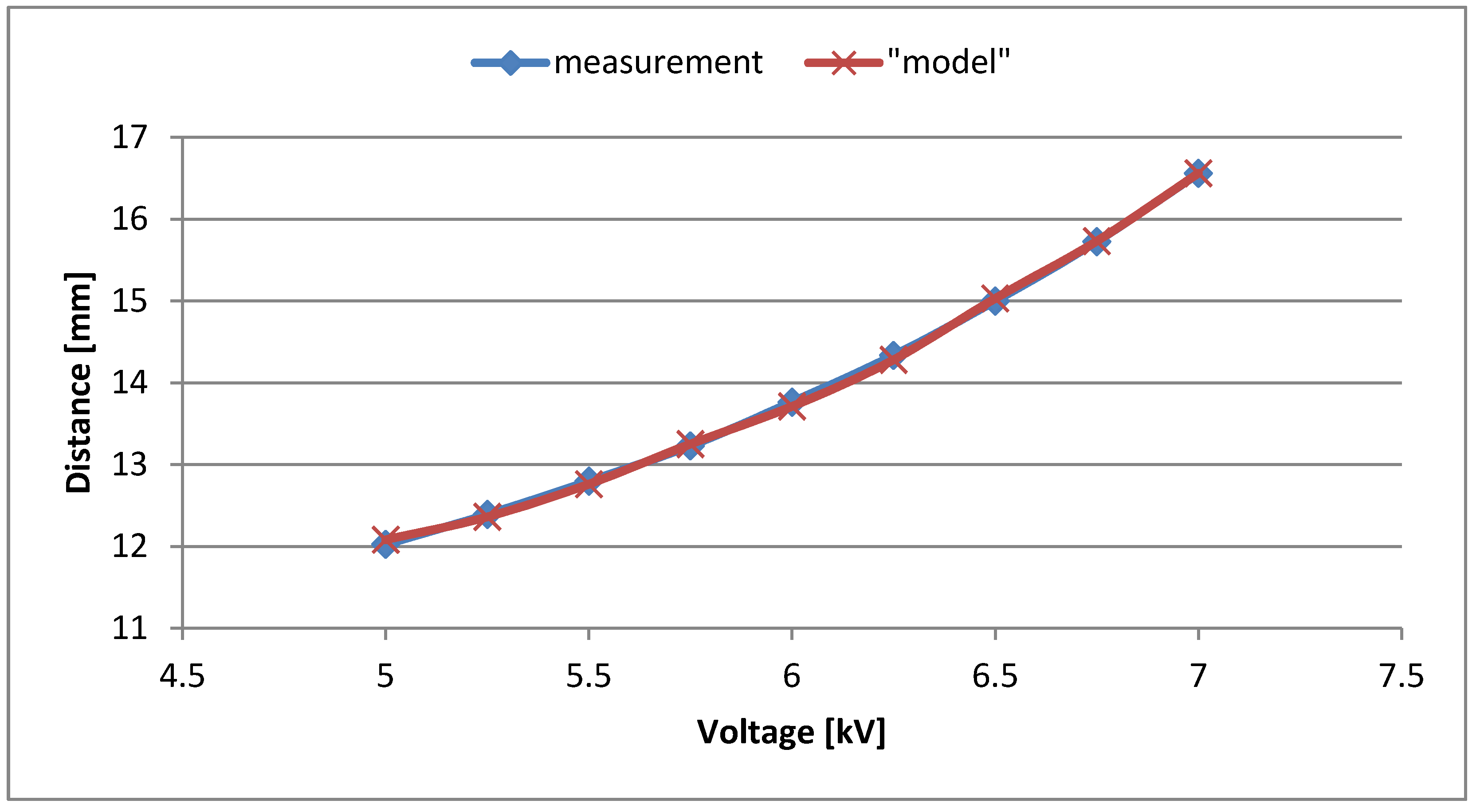
| Voltage Supply [kV] | Displacement Measurement [mm] | Displacement Model [mm] | Virtual Young Modulus [MPa] |
|---|---|---|---|
| 5.00 | 12.02 | 12.08 | 7100 |
| 5.25 | 12.39 | 12.36 | 6950 |
| 5.50 | 12.80 | 12.76 | 6700 |
| 5.75 | 13.23 | 13.25 | 6450 |
| 6.00 | 13.76 | 13.71 | 6250 |
| 6.25 | 14.33 | 14.28 | 6000 |
| 6.50 | 15.00 | 15.03 | 5700 |
| 6.75 | 15.73 | 15.73 | 5450 |
| 7.00 | 16.56 | 16.56 | 5150 |
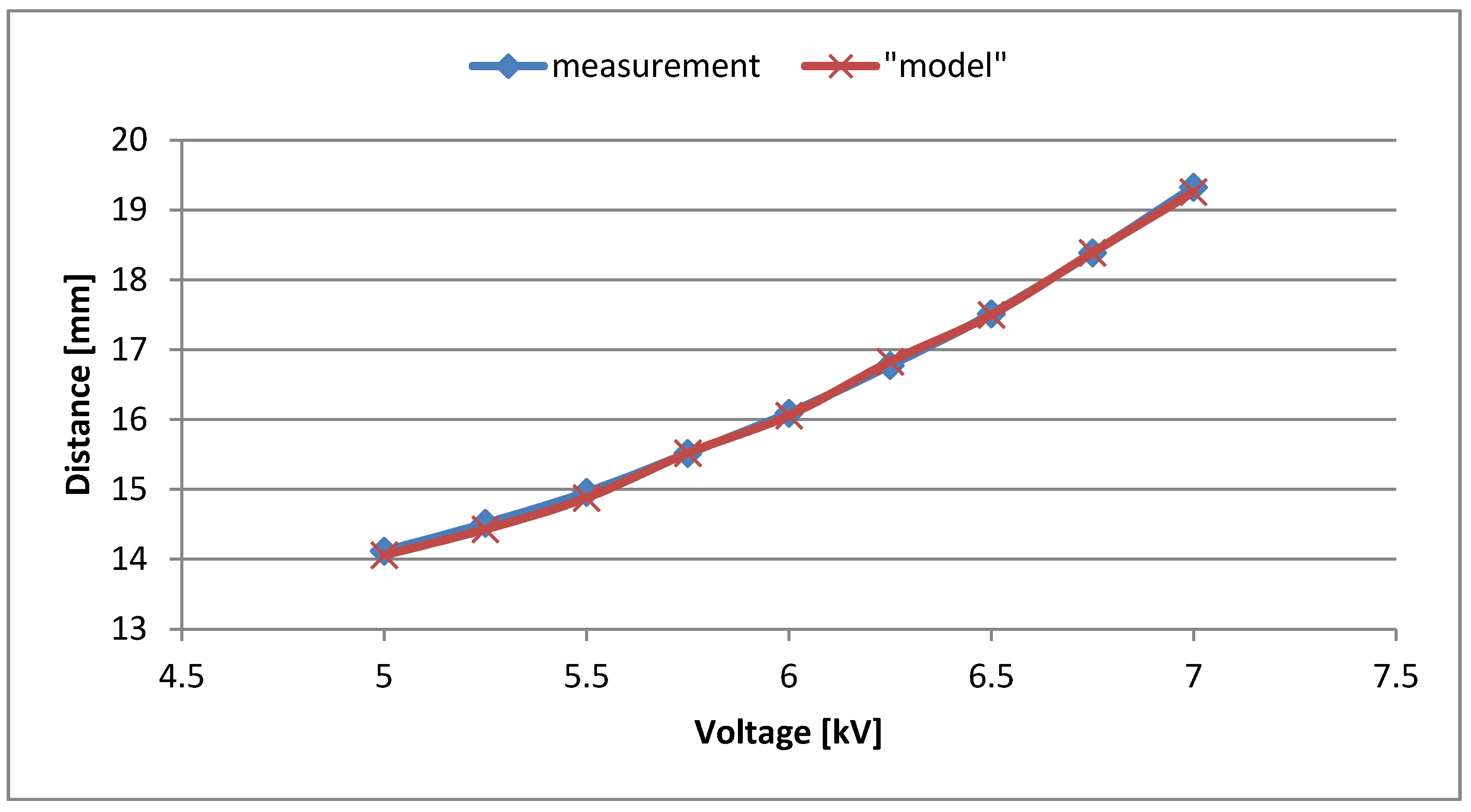
| Voltage Supply [kV] | Displacement Measurement [mm] | Displacement Model [mm] | Virtual Young Modulus [MPa] |
|---|---|---|---|
| 5.00 | 14.12 | 14.06 | 7300 |
| 5.25 | 14.51 | 14.43 | 7100 |
| 5.50 | 14.96 | 14.88 | 6900 |
| 5.75 | 15.51 | 15.52 | 6625 |
| 6.00 | 16.09 | 16.06 | 6400 |
| 6.25 | 16.78 | 16.83 | 6075 |
| 6.50 | 17.51 | 17.50 | 5850 |
| 6.75 | 18.39 | 18.39 | 5575 |
| 7.00 | 19.33 | 19.26 | 5300 |
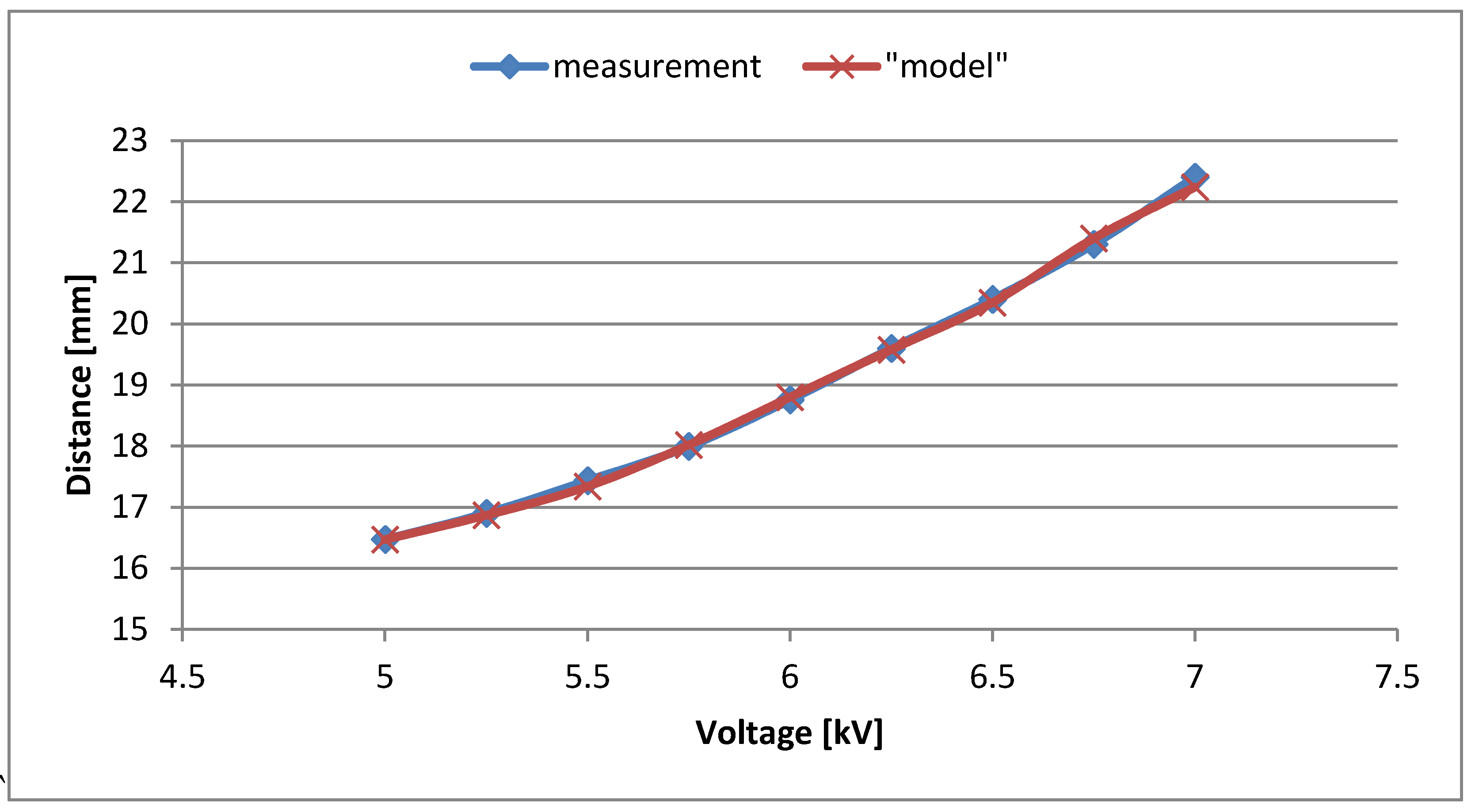
| Voltage Supply [kV] | Displacement Measurement [mm] | Displacement Model [mm] | Virtual Young Modulus [MPa] |
|---|---|---|---|
| 5.00 | 16.47 | 16.47 | 7200 |
| 5.25 | 16.90 | 16.87 | 6975 |
| 5.50 | 17.43 | 17.34 | 6775 |
| 5.75 | 18.00 | 18.02 | 6600 |
| 6.00 | 18.76 | 18.8 | 6300 |
| 6.25 | 19.60 | 19.58 | 6050 |
| 6.50 | 20.40 | 20.35 | 5800 |
| 6.75 | 21.30 | 21.40 | 5550 |
| 7.00 | 22.40 | 22.24 | 5300 |
© 2020 by the author. Licensee MDPI, Basel, Switzerland. This article is an open access article distributed under the terms and conditions of the Creative Commons Attribution (CC BY) license (http://creativecommons.org/licenses/by/4.0/).
Share and Cite
Kołota, J. The FEM Model of the Pump Made of Dielectric Electroactive Polymer Membrane. Appl. Sci. 2020, 10, 2283. https://doi.org/10.3390/app10072283
Kołota J. The FEM Model of the Pump Made of Dielectric Electroactive Polymer Membrane. Applied Sciences. 2020; 10(7):2283. https://doi.org/10.3390/app10072283
Chicago/Turabian StyleKołota, Jakub. 2020. "The FEM Model of the Pump Made of Dielectric Electroactive Polymer Membrane" Applied Sciences 10, no. 7: 2283. https://doi.org/10.3390/app10072283
APA StyleKołota, J. (2020). The FEM Model of the Pump Made of Dielectric Electroactive Polymer Membrane. Applied Sciences, 10(7), 2283. https://doi.org/10.3390/app10072283