Abstract
In this paper, we propose a rateless, three-stage, two-way multiply-and-forward (MF) relaying system over the Rayleigh flat fading channel, where two source nodes communicate with each other through a relay node and all nodes work on half-duplex and time-division mode. We thoroughly analyze the signals during all three stages in the proposed MF system and derive the closed-form symbol error rate (SER) expressions for an uncoded MF-two-way relay network (MF-TWRN). Furthermore, we provide the equivalent point-to-point fading channel model, which is employed to carry out the asymptotic performance analysis. We finally put forth an optimization model for the MF-TWRN with fountain codes. Simulation results show that our optimized degree distribution can provide outstanding performance for the MF-TWRN compared to those in the literature.
1. Introduction
Over the past few decades, the two-way relay network (TWRN) [1,2,3,4,5,6,7,8,9,10,11,12,13] has aroused great interest due to the overwhelming development of wireless cellular systems, especially when one-way relaying is of low spectral efficiency because of the half-duplex constraint. In a TWRN system, two source nodes exchange information through a relay node. A TWRN can be realized in three or even two stages with the help of network coding technologies. In the three-stage scheme, source nodes send their corresponding messages to the relay in the first two stages, respectively. In the third stage, the relay processes received signals with either a decode-and-forward (DF) approach [1,2,3,4,5,6] or an amplify-and-forward approach [7,8,9,10,11,12,13], and then broadcasts back to the source nodes. In [14], Xu et al. proposed a multiply-and-forward (MF) approach, in which the relay multiplies the signals sent from different source nodes. More importantly, MF has shown a significant performance increase compared to AF in a three-stage TWRN system [14,15,16,17].
To ensure reliable data transmission in a large-scale network, fountain codes [18,19,20] were proposed and have been well investigated in binary erasure channels and noisy channels [21,22]. Some works have been carried out on designing well-performing degree distributions in noisy channels [22,23,24]. Nguyen et al. proposed the concept of systematic Luby transform (SLT) codes and put forth the truncated robust soliton degree distribution for SLT codes in wireless channels [23]. Xu et al. [24] extended the work of Etesami et al. [22] for raptor codes in memoryless binary symmetric channels to study systematic LT codes in binary input additive white Gaussian noise (BIAWGN) channels and analyzed the asymptotic bit error rate (BER) performance using a Gaussian approximation technique.
To take advantage of relaying systems and rateless codes, we therefore consider employing fountain codes, a class of rateless codes in the TWRN for channel coding at source nodes in this paper. Zhang et al. [25] analyzed a three-stage rateless coded protocol for a DF-TWRN and proposed some related optimization models for rateless codes used at source nodes. Since the relay carries out decoding operations in the DF approach, which is more complex than AF and MF, we focus on fountain-coded two-way MF relaying in this paper. Specifically, we consider the SLT-coded MF-TWRN over Rayleigh flat fading channels. Furthermore, we will investigate BER performance of our proposed MF-TWRN and its corresponding lower bound on BER. In addition, an optimization model will be derived to generate the well performing degree distribution for SLT codes in the MF-TWRN. Our proposed rateless relaying scheme can lead to heuristic designs of TWRN extending the range of wireless transmission, such as in beyond-5G cellular systems and wireless ad hoc networks.
The rest of this paper is organized as follows. Section 2 introduces the system model of three-stage TWRN and Section 3 derives and compares performance of uncoded TWRN with MF and AF schemes. In Section 4, we establish the equivalent point-to-point channel model, and further study BER performance as well as the optimization method for SLT-coded MF-TWRN. Some numerical results are shown in Section 5, and Section 6 concludes the paper.
The key variables and notations used in this paper are summarized in Table A1.
2. System Model
Consider a time-division TWRN, as shown in Figure 1, where two source nodes A and B communicate with each other through a relay node R. Note that all nodes work on half-duplex mode, in which they cannot transmit and receive signals simultaneously. Let and denote the source bit vectors of length , respectively. In this paper, we employ SLT codes for rateless coding and the corresponding output bits are represented as and . We refer readers to [24] and references therein for details about SLT encoding and decoding algorithms. Using BPSK(Binary Phase Shift Keying) modulation, the encoded bits transmitted from the source nodes to the relay node are modulated as
and
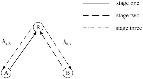
Figure 1.
System model of a two-way relay network.
Let the distance between source node and relay node R denoted by , . Thus, the large-scale path loss is denoted by , where represents the path loss exponent. Assume the channels are Rayleigh-distributed, reciprocal and time-invariant during one round of message exchange between nodes A and B. More importantly, assume channel state information is perfectly known to all receivers of nodes A, B and R, therefore, we will not consider any phase rotation that could cause the change of symbol signs during the transmission, for the simplicity of analysis. Denote the small-scale fading coefficients of each channel by and , respectively, that follow the same Rayleigh distribution, i.e.,
where represents a crucial parameter in the Rayleigh density and we denote the density by Rayleigh(). in this paper. The fading coefficients and are therefore denoted by
with following the exponential distribution
where . Assume all nodes transmit signals with the same power of and Gaussian noise at each node follows the same density with mean zero and variance , denoted by . Using the definition of transmit power and noise, here we can define the transmit signal-to-noise ratio (SNR) as , for all nodes in a TWRN.
In the TRWN that we will discuss in the following sections, it takes three stages to exchange messages between two source nodes:
- a)
- node A sends modulated symbols to node R and the received signal vector is given by
- b)
- node B sends modulated symbols to node R and the received signal vector is given by
- c)
- node R processes the signals received from A and B and broadcasts to nodes A and B with the signalwhere is a factor to ensure power normalization and function represents the processing of received signals at node R, such as DF and AF. Then, the received signals at nodes A and B can be represented asand
Finally, the received signals are processed at each source node to recover source bits from the opposite one. Note that all elements in and are i.i.d (independent and identically distributed). Gaussian variables following , . In addition, the duration of each exchange round is variant since SLT codes are rateless, i.e., each round comes to an end when both transmitters receive acknowledge from the corresponding destinations.
3. Analysis on Uncoded TWRN
3.1. AF Scheme
In the traditional AF scheme, relay node R adds the received signals from nodes A and B together at the third stage and we have
where denotes the normalization factor in the AF scheme, so that
Substituting (6) and (7) into (12), we can further derive
Due to the similarity of signal processing at nodes A and B, we take source node A for example to describe the processing in details. Employing (6), (7), (9) and (11), the received signal at node A is given by
where represents the sum of white Gaussian distributed noise and , which implies that all elements in are independently and identically distributed by . Given that the channel state information is well known to both receivers, node A can subtract its own source signal from the received one and get
For a coded system, node A can further employ the belief propagation (BP) algorithm to decode the source information from (15). Moreover, the received SNR at node A derived from (15) is given by
Similarly, the received SNR at node B is given by
With the given channel state information and , the symbol error ratio (SER) for an uncoded BPSK-modulated symbol can be yielded according to the received SNR [26], taking source symbol at node A, for example:
Furthermore, the mean SER can be derived considering Rayleigh fading channels, i.e.,
where denotes the moment generating function (MGF) of variable , i.e.,
and denotes the probability density function of . In particular, Lemma 1 introduces a more simplified expression of in the high SNR regime.
Lemma 1.
([27]) When can be expressed as the harmonic mean of two exponential distributed random variables with parameters and , respectively, the MGF in the sufficiently high SNR regime can be approximated as
Accordingly, the mean SER of a BPSK-modulated AF-TWRN is introduced in the following theorem.
Theorem 1.
In the high SNR regime, when source nodes transmit uncoded BPSK symbols in a three-stage AF-TWRN over the flat Rayleigh fading channel, the mean SER of AF-TWRN is derived as
Proof:
Let us approximate the received SNR at node A in the high SNR regime as
It is clear that in (23) is the harmonic mean of and . Since and follow exponential distributions with parameters and respectively, the MGF of can be well approximated by
according to Lemma 1.
Substituting (24) into (19), we can yield the mean SER at node A as
Similarly, the mean SER at node B is given by
According to the results in (25) and (26), the mean SER of a BPSK-modulated AF-TWRN is given by
□
3.2. MF Scheme
The relay node will amplify the noise in the AF scheme, which may cause severe error expansion problems, though the processing of the AF scheme is relatively simple. Therefore, this section presents a more efficient MF scheme and the performance in the flat Rayleigh fading channel is studied.
In the MF scheme, relay node R multiplies signals from different source nodes before broadcasting. Therefore, at the third stage, the signal processed by relay node R is shown as
where represents the Hadamard product of vectors, which is a product operation performed on corresponding elements in vectors of the same dimensions, and denotes the power normalization factor, so that
Substituting (6) and (7) into (29), then we have
Hence, in the MF scheme, the signal received from relay node R at node A can be described as
To eliminate its own source signal of node A, simply multiply with the conjugate signal of and we have
Based on (32), we can observe that all the terms are noise-related except the one containing . The noise terms are with mean zero and variance . Since the product of two Gaussian noise is trivial when the noise variance is much less than the transmit power , the noise terms can be roughly approximated as Gaussian in the high SNR. BP decoding algorithm is then utilized to recover the original symbol . For in (32), the received SNR at source node A in the MF scheme is defined as
Similarly, the received SNR at source node B is given by
Then, the mean SER of MF-TWRN with BPSK modulation is proposed in Theorem 2.
Theorem 2.
In the high SNR regime, when source nodes transmit uncoded BPSK symbols in a three-stage MF-TWRN over the flat Rayleigh fading channel, the mean SER of MF-TWRN is derived as
Proof:
For the convenience of theoretical analysis, an approximation is performed on (33) to simplify the complicated expression of received SNR in the MF scheme. In the high SNR regime, the quadratic term of power is much larger than the linear term so that the received SNR at source node A can be approximated as
in which the linear term of and noise term are ignored. By means of the harmonic mean, (36) can be reformed as
As the SER derived in (19) for the AF scheme, the mean SER at source node A in the flat Rayleigh fading channel for the MF scheme is given by
Based on (37), the MGF of in the high SNR regime can be approximately expressed by
Substituting (39) into (38), the mean SER at source node A in the MF scheme is derived as
Similarly, the mean SER at source node B in the MF scheme is derived as
Therefore, the mean SER of a BPSK-modulated MF-TWRN is given by
A comparison between (22) and (35) indicates
which shows that, with the same SNR, the performance of MF scheme proposed in this section is better than that of traditional AF scheme in the flat Rayleigh fading channel. □
4. Fountain-coded MF-TWRN
Based on the analysis of three-stage TWRN with different relaying schemes, the performance of AF and MF has been compared by SER derivations in an uncoded system. In this section, asymptotic analysis of rateless coded MF-TWRN is further studied when SLT codes are employed at source nodes and then the corresponding optimization model is proposed to improve the performance of SLT-coded MF-TWRN.
4.1. Asymptotic Analysis
According to (32), the MF-TWRN channel from node B to node A is equivalent to a point-to-point fading channel shown in Figure 2. The BPSK-modulated symbol is transmitted with unit power and the channel fading coefficient is given by . The equivalent Gaussian noise satisfies
with mean zero and variance
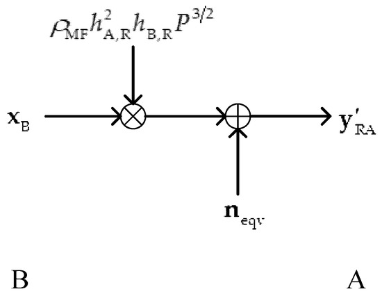
Figure 2.
The equivalent point-to-point fading channel model from node B to node A.
In the flat Rayleigh fading channel, coefficients and remain invariant during an information exchange between nodes A and B. Therefore, with known and , the method we proposed in [24] can be used for the decoding and performance analysis of SLT codes in the channel model shown in Figure 2. With the received signal in(32), when the logarithm domain BP decoding algorithm is utilized for the decoder, the initial log-likelihood ratio (LLR) message is given by
When all-zero codewords are transmitted, the initial LLR message in (46) follows the symmetric Gaussian distribution . Therefore, with known and , the lower bound on BER at node A is given by [24]
where represents the mean degree of degree distribution used in LT codes for source nodes. Employing Rayleigh density in (3), the mean lower bound on BER at node A can be calculated by means of
while the mean lower bound at node B is given by
Then, the mean lower bound on BER of SLT-coded MF-TWRN in the flat Rayleigh fading is derived as
Specifically, an approximation of the mean lower bound in a three-stage MF-TWRN with respect to high SNRs is proposed in Theorem 3.
Theorem 3.
In the high SNR regime, with SLT coding and BPSK modulation, the mean lower bound on BER of the three-stage MF-TWRN in the flat Rayleigh fading channel is derived as
Proof:
With given and , the lower bound on BER at node A can be approximated by [24]
Then, the MGF described in (39) can be used to derive the mean lower bound in the high SNR regime, i.e.,
Similarly, the mean lower bound on BER at node B in the high SNR regime is described as
Therefore, the mean lower bound on BER of SLT-coded three-stage MF-TWRN is given by
□
Because the channels between two source nodes and the relay node are asymmetric, nodes A and B may decode the received signals correctly with different overheads. In order to consider the overall efficiency of information exchanges in the TWRN, the corresponding definition of throughput is introduced as the following.
Definition 1.
During an information exchange, assume the overheads that nodes A and B need for successful decoding are and , respectively. Then, the throughput of TWRN, i.e., the number of useful information bits contained in a one-bit transmission, can be defined as
where .
With given and , the equivalent channel capacity between nodes A and B can be derived by substituting the received SNRs and into [18]
where represents the BIAWGN channel capacity. Then, the capacities of equivalent channel between nodes A and B are shown as
and
where represents the equivalent channel capacity from node B to A, while represents the reverse one. Therefore, the theoretical upper bound on the throughput of MF-TWRN in an information exchange is given by
where
Consider Rayleigh distributed channel fading coefficients, the mean upper bound on throughput for MF-TWRN in the flat Rayleigh fading channel is represented by
4.2. Optimization Design
In order to successfully decode the BPSK-modulated SLT codes in the noisy channel, the mean value of LLR messages should increase from iteration to iteration during BP decoding. Obviously, it is necessary to satisfy this condition for different received SNRs so that SLT-coded MF-TWRN could achieve good performance in the flat Rayleigh fading channel. Assume denotes the set of received SNRs in MF-TWRN. For , the aforementioned condition can be described as
where represents the mean of LLR messages in the iteration, and
where
Inspired by the optimization model we have proposed for BPSK-modulated SLT codes in the BIAWGN channel [24], the optimization model of degree distribution for SLT-coded MF-TWRN in the flat Rayleigh fading channel is proposed in what follows, aiming at minimizing the average degree with main constraints introduced by (50) and (63):
where represents the equidistant points in the interval . The values of , , , and should be determined in advance, serving as control variables. For the practical use of this optimization model, discretization is generally performed on the set of received SNR, and we make use of a quasi-Newton method to iterate toward a solution of optimized degree distribution.
5. Simulation Results
In this section, we offer simulation results to validate our work on the design of rateless MF-TWRN. In our simulation, the transmit power of all nodes is normalized and the distances between the relay node and source nodes are identical with the value of 1. Moreover, assume the path loss exponent is of 2. The channel fading coefficients are with unit power, i.e., , .
For an uncoded TWRN system with BPSK modulation, Figure 3 demonstrates the SER performance of two forwarding schemes, namely, MF and AF, over the flat Rayleigh fading channel, regarding theoretical and simulation results. The solid lines in Figure 3 depict numerical results of MF and AF, respectively, while the dotted lines are plotted using theoretical results in (22) and (35). It is implied that the numerical SERs can be approximated by theoretical ones, coinciding in the sufficiently high SNR regime especially. Just like the conclusion drawn in the Section 3, numerical results also show that the MF scheme outperforms the AF scheme in the flat Rayleigh channel.
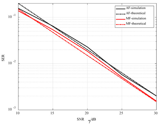
Figure 3.
Symbol error rate (SER) performance comparison of different forwarding schemes over the flat Rayleigh fading channel.
Using the optimization model proposed in (66), Table A2 offers the optimized result with parameters , , and , which is denoted by . The authors in [25] studied the design of fountain codes in a three-stage TWRN using joint network-channel coding. Their optimized distribution was obtained with the channel condition as well and is denoted by for short. In the flat Rayleigh fading channel with the transmit SNR of 20dB, Figure 4 and Figure 5 demonstrate the BER performance of MF-TWRN at node A with different lengths of source information, when using the optimized distribution . It is clear that the BER decreases as the source length increases from 2000 to 4000, and approaches the theoretical lower bound especially in the high overhead regime. This observation made on Figure 4 and Figure 5 also validate the theoretical analysis carried out in Section 4. To compare the overall performance of a TWRN system thoroughly, Figure 6, Figure 7 and Figure 8 show the performance of MF-TWRN from the perspectives of frame-error-rate (FER) and throughput, respectively. Figure 6 and Figure 7 compare the mean FER of two source nodes using different optimized distributions and the comparison results imply that our optimized distribution can improve the decoding performance of the whole TWRN system. Furthermore, Figure 8 describes the throughput of MF-TWRN using different degree distributions, in which the numerical results are obtained for the source length of 4000 while the theoretical results correspond to upper bounds on the throughput derived in (62). Along with the increase of the SNR, the actual throughput of TWRN approaches the theoretical upper bound. One can get a higher throughput using the optimized distribution rather than proposed in [25], which means information exchanges can be successfully made with a smaller overhead. Especially in the low SNR regime, we can observe a 1dB gain with respect to the throughput. In other words, with the same transmit SNR, almost 20% of the overhead can be saved to ensure a less time-consuming information exchanges between source nodes. The comparison of MF and AF theoretical throughputs in Figure 8 is in accordance with what is offered in Figure 3, which validates the superiority of MF forwarding scheme over the flat Rayleigh fading channel.
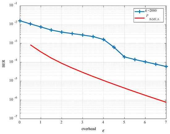
Figure 4.
Bit error rate (BER) performance of source node A when using with .
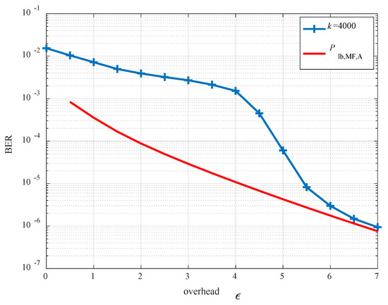
Figure 5.
BER performance of source node A when using with .
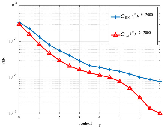
Figure 6.
Frame error rate (FER) performance of systematic Luby transform (SLT)-coded multiply-and-forward two-way relay network (MF-TWRN) using different degree distributions with .
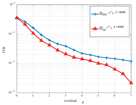
Figure 7.
FER performance of SLT-coded MF-TWRN using different degree distributions with .
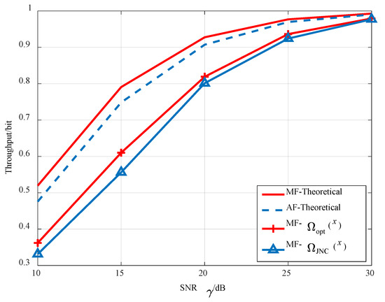
Figure 8.
Throughputs of the SLT-coded TWRN system with different degree distributions.
6. Conclusions
In this paper, we investigated a fountain-coded MF-TWRN in the Rayleigh flat fading channel. Specifically, SLT codes are applied at both source nodes. The SERs of uncoded TWRN with different forwarding schemes were first derived and the theoretical analysis proved that our proposed MF-TWRN outperforms the traditional AF-TWRN. To analyze the BER performance of the proposed network, we first offered the equivalent channel model from the perspective of a point-to-point communication system. Using this equivalent channel model, we then studied the lower bound on BER in the MF-TWRN. The corresponding degree distribution was optimized for the Rayleigh flat fading channel. Through simulations, it is shown that our degree distribution has a significant BER performance increase for the proposed MF-TWRN compared to other degree distributions in the literature. In the future work, we will consider a more general application scenario, for example, asymmetric channels.
Author Contributions
All the authors contributed extensively to the work presented in this paper. W.H. and S.X. conceived the original idea, and W.H. implemented all the experiments for the study; S.X. contributed to the article’s organization and provided suggestions that improved the quality of the paper; D.H. revised the manuscript and guided the overall research; C.X. provided the computing resources and co-guided the research. All authors have read and agreed to the published version of the manuscript.
Funding
This work was supported by Funding of Jiangsu Innovation Program for Graduate Education, the Fundamental Research Funds for the Central Universities (Grant No. KYLX15_0287), National Natural Science Foundation of China (61601222), Natural Science Foundation of Jiangsu Province (BK20160789), China Postdoctoral Science Foundation (2018M632303).and National Key Research and Development Project (Grant No.2017YFC0822404).
Conflicts of Interest
The authors declare no conflict of interest.
Appendix A

Table A1.
Summarization of Key Variables and Notations.
Table A1.
Summarization of Key Variables and Notations.
| Source Vector | |
|---|---|
| received vector | |
| channel fading coefficient | |
| distance between source and relay node | |
| path loss exponent | |
| signal-to-noise ratio | |
| transmit power | |
| power normalization factor | |
| Gaussian density with mean and variance | |
| mathematical expectation | |
| degree distribution | |
| Moment generating function of | |
| Hadamard product of vectors and |
Appendix B
Table A2.
Optimized Degree Distribution for MF-TWRN by the Proposed Model.
Table A2.
Optimized Degree Distribution for MF-TWRN by the Proposed Model.
| 1 | 0.0853 | 42 | 0.0002 | 74 | 0.0002 | 106 | 0.0002 |
| 2 | 0.2421 | 43 | 0.0002 | 75 | 0.0002 | 107 | 0.0002 |
| 3 | 0.0917 | 44 | 0.0002 | 76 | 0.0002 | 108 | 0.0002 |
| 4 | 0.1955 | 45 | 0.0002 | 77 | 0.0002 | 109 | 0.0002 |
| 5 | 0.0616 | 46 | 0.0002 | 78 | 0.0002 | 110 | 0.0002 |
| 6 | 0.0522 | 47 | 0.0002 | 79 | 0.0002 | 111 | 0.0002 |
| 7 | 0.0459 | 48 | 0.0002 | 80 | 0.0002 | 112 | 0.0002 |
| 8 | 0.0761 | 49 | 0.0002 | 81 | 0.0002 | 113 | 0.0002 |
| 9 | 0.0333 | 50 | 0.0002 | 82 | 0.0002 | 114 | 0.0002 |
| 10 | 0.0270 | 51 | 0.0002 | 83 | 0.0002 | 115 | 0.0002 |
| 11 | 0.0207 | 52 | 0.0002 | 84 | 0.0002 | 116 | 0.0002 |
| 12 | 0.0144 | 53 | 0.0002 | 85 | 0.0002 | 117 | 0.0002 |
| 13 | 0.0081 | 54 | 0.0002 | 86 | 0.0002 | 118 | 0.0002 |
| 14 | 0.0203 | 55 | 0.0002 | 87 | 0.0002 | 119 | 0.0002 |
| 24 | 0.0001 | 56 | 0.0002 | 88 | 0.0002 | 120 | 0.0002 |
| 25 | 0.0001 | 57 | 0.0002 | 89 | 0.0002 | 121 | 0.0002 |
| 26 | 0.0001 | 58 | 0.0002 | 90 | 0.0002 | 122 | 0.0002 |
| 27 | 0.0001 | 59 | 0.0002 | 91 | 0.0002 | 123 | 0.0002 |
| 28 | 0.0001 | 60 | 0.0002 | 92 | 0.0002 | 124 | 0.0002 |
| 29 | 0.0001 | 61 | 0.0002 | 93 | 0.0002 | 125 | 0.0001 |
| 30 | 0.0005 | 62 | 0.0002 | 94 | 0.0002 | 126 | 0.0001 |
| 31 | 0.0001 | 63 | 0.0002 | 95 | 0.0002 | 127 | 0.0001 |
| 32 | 0.0001 | 64 | 0.0002 | 96 | 0.0002 | 128 | 0.0001 |
| 33 | 0.0011 | 65 | 0.0002 | 97 | 0.0002 | 129 | 0.0001 |
| 34 | 0.0001 | 66 | 0.0002 | 98 | 0.0002 | 130 | 0.0001 |
| 35 | 0.0001 | 67 | 0.0002 | 99 | 0.0002 | 131 | 0.0001 |
| 36 | 0.0002 | 68 | 0.0002 | 100 | 0.0002 | 132 | 0.0001 |
| 37 | 0.0002 | 69 | 0.0002 | 101 | 0.0002 | 133 | 0.0001 |
| 38 | 0.0002 | 70 | 0.0002 | 102 | 0.0002 | 134 | 0.0001 |
| 39 | 0.0002 | 71 | 0.0002 | 103 | 0.0002 | 135 | 0.0001 |
| 40 | 0.0002 | 72 | 0.0002 | 104 | 0.0002 | 136 | 0.0001 |
| 41 | 0.0002 | 73 | 0.0002 | 105 | 0.0002 | 200 | 0.0008 |
References
- Waheed, M.; Ahmad, R.; Ahmed, W.; Drieberg, M.; Alam, M.M. Towards Efficient Wireless Body Area Network Using Two-Way Relay Cooperation. Sensors 2018, 18, 565. [Google Scholar] [CrossRef]
- Hieu, T.D.; Duy, T.T.; Dung, L.T.; Choi, S.G. Performance Evaluation of Relay Selection Schemes in Beacon-Assisted Dual-Hop Cognitive Radio Wireless Sensor Networks under Impact of Hardware Noises. Sensors 2018, 18, 1843. [Google Scholar] [CrossRef]
- Larsson, P.; Johansson, N.; Sunell, K.E. Coded bi-directional relaying. In Proceedings of the 2006 IEEE 63rd Vehicular Technology Conference, Melbourne, VICAustralia, 7–10 May 2006. [Google Scholar]
- Kim, S.J.; Mitran, P.; Tarokh, V. Performance bounds for bi-directional coded cooperation protocols. IEEE Trans. Inf. Theory 2008, 54, 5235–5241. [Google Scholar] [CrossRef]
- Rankov, B.; Wittneben, A. Spectral efficient protocols for half-duplex fading relay channels. IEEE J. Sel. Areas Commun. 2007, 25, 379–389. [Google Scholar] [CrossRef]
- Peng, C.; Li, F.; Liu, H.; Wang, G. Outage-Based Resource Allocation for DF Two-Way Relay Networks with Energy Harvesting. Sensors 2018, 18, 3946. [Google Scholar] [CrossRef]
- Popovski, P.; Yomo, H. Wireless network coding by amplify-and- forward for bi-directional traffic flows. IEEE Commun. Lett. 2007, 11, 16–18. [Google Scholar] [CrossRef]
- Han, Y.; Ting, S.H.; Ho, C.K.; Chin, W.H. Performance bounds for two-way amplify-and-forward relaying. IEEE Trans. Wirel. Commun. 2009, 8, 432–439. [Google Scholar] [CrossRef]
- Ping, J.; Ting, S.H. Rate performance of AF two-way relaying in low SNR region. IEEE Commun. Lett. 2009, 13, 233–235. [Google Scholar] [CrossRef]
- Zhang, R.; Liang, Y.C.; Chai, C.C.; Cui, S. Optimal beamforming for two-way multi-antenna relay channel with analogue network coding. IEEE J. Sel. Area Commun. 2009, 27, 699–712. [Google Scholar] [CrossRef]
- Berger, S.; Kuhn, M.; Wittneben, A. Recent advances in amplify-and-forward two-hop relaying. IEEE Commun. Mag. 2009, 47, 50–56. [Google Scholar] [CrossRef]
- Roemer, F.; Haardt, M. Algebraic norm-maximizing (ANOMAX) transmit strategy for two-way relaying with MIMO amplify and forward realys. IEEE Trans. Signal Process. Lett. 2009, 16, 909–912. [Google Scholar] [CrossRef]
- Sahajwani, M.; Jain, A.; Gamad, R. Log Likelihood Ratio Based Relay Selection Scheme for Amplify and Forward Relaying with Three State Markov Channel. Future Internet 2018, 10, 87. [Google Scholar] [CrossRef]
- Xu, S.; Xu, D.; Zhang, X.; Shao, H. Two-way relay networks based on product relay. Electron. Lett. 2015, 51, 429–430. [Google Scholar] [CrossRef]
- Shah, S.T.; Choi, K.W.; Hasan, S.F.; Chung, M.Y. Energy harvesting and information processing in two-way multiplicative relay networks. Electron. Lett. 2016, 52, 751–753. [Google Scholar] [CrossRef]
- Ye, Y.; Li, Y.; Wang, Z.; Chu, X.; Zhang, H. Dynamic asymmetric power splitting scheme for SWIPT based two-way multiplicative AF relaying. IEEE Signal Process. Lett. 2018, 25, 1014–1018. [Google Scholar] [CrossRef]
- Wang, Z.; Li, Y.; Ye, Y.; Zhang, H. Dynamic power splitting for three-step two-way multiplicative AF relay networks. In Proceedings of the 86th IEEE Vehicular Technology Conference, Toronto, ON, Canada, 24–27 September 2017; pp. 1–5. [Google Scholar]
- MacKay, D.J.C. Fountain codes. IEEE Proc. Commun. 2005, 152, 1062–1068. [Google Scholar] [CrossRef]
- Luby, M. LT codes. In Proceedings of the 43rd Annual IEEE Symposium on Foundations of Computer Science, Vancouver, BC, Canada, 16–19 November 2002. [Google Scholar]
- Shokrollahi, A. Raptor codes. IEEE Trans. Inf. Theory 2006, 52, 2551–2567. [Google Scholar] [CrossRef]
- Palanki, R.; Yedidia, J.S. Rateless codes on noisy channels. In Proceedings of the International Symposium on Information Theory, Chicago, IL, USA, 27 June–2 July 2004. [Google Scholar]
- Etesami, O.; Shokrollahi, A. Raptor codes on binary memoryless symmetric channels. IEEE Trans. Inf. Theory 2006, 52, 2033–2051. [Google Scholar] [CrossRef]
- Nguyen, T.D.; Yang, L.L.; Ng, S.X.; Hanzo, L. An optimal degree distribution design and a conditional random integer generator for the systematic Luby transform coded wireless Internet. In Proceedings of the 2008 IEEE Wireless Communications and Networking Conference (WCNC), Las Vegas, NV, USA, 31 March–3 April 2008; pp. 243–248. [Google Scholar]
- Xu, S.; Xu, D. Optimization design and asymptotic analysis of systematic Luby transform codes over BIAWGN channels. IEEE Trans. Commun. 2016, 64, 3160–3168. [Google Scholar] [CrossRef]
- Zhang, Y.; Zhang, Z.; Yin, R.; Yu, G.; Wang, W. Joint network-channel coding with rateless code in two-way relay systems. IEEE Trans. Wirel. Commun. 2013, 12, 3158–3169. [Google Scholar] [CrossRef]
- Simon, M.K.; Alouini, M.S. Digital Communication over Fading Channels–A Unified Approach to Performance Analysis, 1st ed.; Wiley: New York, NY, USA, 2000. [Google Scholar]
- Su, W.; Sadek, A.K.; Liu, K.J.R. Cooperative communication protocols in wireless networks: Performance analysis and optimum power allocation. Wireless Pers. Commun. 2008, 44, 181–217. [Google Scholar] [CrossRef]


© 2020 by the authors. Licensee MDPI, Basel, Switzerland. This article is an open access article distributed under the terms and conditions of the Creative Commons Attribution (CC BY) license (http://creativecommons.org/licenses/by/4.0/).