Article

Development and Application of a Pre-Corrected Fast Fourier Transform Accelerated Multi-Layer Boundary Element Method for the Simulation of Shallow Water Acoustic Propagation

1
Department of Mechanical Engineering, Massachusetts Institute of Technology, Cambridge, MA 02139, USA
2
School of Civil Engineering, Tianjin University, Tianjin 300072, China
*
Author to whom correspondence should be addressed.
Appl. Sci. 2020, 10(7), 2393; https://doi.org/10.3390/app10072393
Submission received: 3 March 2020 / Revised: 26 March 2020 / Accepted: 29 March 2020 / Published: 1 April 2020
(This article belongs to the Section Acoustics and Vibrations)

Abstract

:
Because of the complexities associated with the domain geometry and environments, accurate prediction of acoustics propagation and scattering in realistic shallow water environments by direct numerical simulation is challenging. Based on the pre-corrected Fast Fourier Transform (PFFT) method, we accelerated the classical boundary element method (BEM) to predict the acoustic propagation in a multi-layer shallow water environment. The classical boundary element method formulate the acoustics propagation problem as a linear equation system in the form of [A]{x}={b}, where [A] is an N×N dense matrix composed of influence coefficients. Solving such linear equation system requires O(N2/N3) computational cost for iterative/direct methods. The developed method, PFFT-BEM, can effectively reduce the computational efforts for direct numerical simulations from O(N2~3) to O(Nlog N), where N is the total number of boundary unknowns. To numerically simulate the sound propagation in a shallow water environment, we applied the first-order non-reflecting boundary condition in the truncated numerical domain boundary to eliminate the errors due to reflected waves. Multi-layer coupled formulation was used to include the environment inhomogeneity in PFFT-BEM. Through multiple convergence tests on the number of layers and elements, we validated and quantified the accuracy of PFFT-BEM. To demonstrate the usefulness and capability of the developed PFFT-BEM, we simulated three-dimensional (3D) underwater sound propagation through 3D geometries to check the efficacy of the established classical method: the 3D Parabolic equation model. Finally, PFFT-BEM was employed to simulate sound propagation through a complex multi-layer shallow water environment with internal waves. The “3D+T” results obtained by PFFT-BEM compared well with the physical test, thereby proving the capability and correctness of this method.

1. Introduction

The accurate forecasting of acoustics wave propagation and scattering in shallow water environments is important in naval operations and underwater communications. A large number of theoretical studies have been carried out to model the sound scattering effects in complex underwater environments in three dimensions (3D). The 3D coupled mode method could produce efficient and accurate prediction of the sound field for specified geometries (e.g., 3D axisymmetric geometry [1,2], longitudinal invariant geometry [3]). The 3D ray model has been proposed for high frequency sound propagation ([4]). The 3D parabolic equation (PE) method is another powerful tool for the prediction of 3D sound propagation (e.g., [5]). Although several newly developed PE models, including two-way scattering, have been developed, generally for two-dimensional (2D) cases [6,7] and for 3D cases formulated in cylindrical coordinates [8], PE is mostly used for the prediction of one-way sound propagation as backward propagation is generally neglected in this method.
For direct numerical simulations (i.e., discretization methods without any assumptions), despite the continued development of computing capabilities, it is a challenge to perform 3D simulations of ocean acoustics in realistic environments due to the high computational costs. Volume discretization methods, such as the finite element method (FEM), finite volume method (FVM), and finite difference method (FDM), require fine meshes over the entire volume of the computational domain. Due to the large computational domain (~O(10) km) and the small acoustic wavelength (~O(1~10) m), the 3D mesh entails a large computational cost. By only discretizing the domain, the boundary discretization method or boundary element method (BEM) has a much lower computational cost than the volume discretization methods. By discretizing the domain boundaries and interfaces into boundary elements, BEM numerically formulate the acoustics propagation problem as a linear equation system in the form of [A]{x} = {b}. Matrix [A] is an N×N dense matrix composed of influence coefficients. Normally, this linear equation system requires O(N2) operations to be constructed and O(N2)/ O(N3) to be solved by iterative/direct solvers. For applications in real shallow water acoustics, N is often in the order of O(106~8). This induces a large computational cost and limits the use of BEM in real shallow water acoustics. Another major drawback of BEM is that classical BEM can only formulate the linear equation system for underwater medium with homogeneous properties (e.g., density and sound speed). However, complex shallow water environments with density and sound speed variations cannot be represented by a single homogeneous fluid layer.
In this study, to overcome the computational cost difficulty in BEM, we used the pre-corrected fast Fourier transform (PFFT) approach to accelerate the BEM solver for the calculation of acoustics propagation in a shallow water environment. The pre-corrected fast Fourier transform (PFFT) approach has been used to increase the speed of the BEM solver from (N2) to (N log N) in different areas (e.g., [9,10,11]). By using PFFT, we can reduce the computational cost in the order of O(106~8). Compared with existing studies using PFFT for underwater acoustics problems (i.e., [11]), the present study made the following contributions. First, to overcome drawbacks due to homogenous assumptions, we simulated the medium inhomogeneity by coupling of multiple homogeneous sub-layers at their interfaces. Through a numerical test, we checked the convergence of the multilayer PFFT-BEM (Version 2019, Massachusetts Institute of Technology, Cambridge, MA, USA, 2019) with respect to the number of sub-layers to validate the accuracy of the multi-layer formulation in our method. Secondly, the accuracy of the BEM method will become progressively worse when moving closer to the domain boundary if an inaccurate far field radiation boundary condition is imposed at the truncated computational domain boundary. In the present method, we applied accurate first-order non-reflecting boundary conditions (NRBCs) in the truncated domain boundary. We utilized the 2D normal mode method to obtain the propagation wave modes near the domain boundary, which are needed for the application of the first-order NRBC. The accuracy of the truncated boundary condition was validated against existing benchmark solutions. Due to the full-field simulation capability, our method could serve as a benchmark solution for comparing and assessing the performance of the classical established model: the 3D Parabolic Equation model. To do that, we conduct 3D simulations to benchmark low–mid frequency acoustics over kilometer ranges for the prediction of 3D sound scattering in three complex underwater environments: a 3D Acoustical Society of America (ASA) wedge, a 3D seamount, and an underwater canyon. We also demonstrate the practical 3D+T simulation capability of PFFT-BEM for underwater acoustics scattering problems. Here, 3D+T refers to time-stepped, frozen-field modeling of underwater sound. Because sound moves at 1.5 km/s in the ocean, pulsed sound traveling hundreds of kilometers could, in principle, be modeled by updating the medium condition over the excursion time of hundreds of seconds as the sound moves away from the sound sources. Using 3D+T PFFT-BEM (Version 2019, Massachusetts Institute of Technology, Cambridge, MA, USA, 2019), we simulate sound scattering variations due to the change in medium properties caused by internal traveling waves, and we compare the numerical results with field tests.

2. Numerical Method

2.1. Formulation of the Boundary Element Method

Consider the following 3D Helmholtz wave equation:
ρ · ( 1 ρ p ( x ) ) k 2 p ( x ) = 0 ,     x V ,
where   x = (x,y,z), p ( x ) is acoustics pressure, and ρ , V, k is the density, volume and wavenumber of the medium, respectively. At the interface between the medium and atmosphere, pressure release boundary condition is satisfied as:
p ( x ) = 0 , x S F ,
where S F is the free surface. The Sommerfeld radiation condition is defined at S :
p ( x ) n i k p ( x ) = 0 ,     x ,
where n is the normal direction on the boundaries.
For shallow water environments, a multilayer model is adopted to account for the inhomogeneous medium properties. In this model, we assume the density ρ and sound speed c in each layer to be constant at every instant of time. A sketch of the multilayer domain is shown in Figure 1.
Then, at every instant of time, the homogeneous Helmholtz equation governing the sound field in each layer can be expressed as
2 p i ( x ) + k 2 p i ( x ) = 0 ,       x v i ,
where i is the number of layers with i = 1, ∆, I, and v i is the volume of layer i. Continuity of pressure and particle velocity are required across the interface S ^ i + 1 ( S ˇ i ) of neighboring layers v i + 1 and v i (including at the penetrable bottoms). We define the bottom and top boundaries of the layer i as the symbols ‘’ and ‘’, respectively. Continuity boundary condition across the interface can be expressed as
p i = p i + 1 ,       x S ^ i + 1 ,
1 ρ i p i n = 1 ρ i + 1 p i + 1 n ,       x S ^ i + 1 .
From Green’s second theorem, the boundary integral equation (BIE) for the pressure p i ( x ) in each layer is derived from Equation (1) as
4 π p i S i + S R i p n i ( ξ ) G ( x ; ξ ) d S i ( ξ ) + S i + S R i p i ( ξ ) G n ( x ; ξ ) d S i ( ξ ) = 0 ,
where Si represents the top and bottom surface of each layer, SRi is the radiation boundary in the far field, G ( x ; ξ ) = 1 | x ξ | e i k | x ξ | and ξ is a dummy variable representing the point on the layer boundary S.
Because the Green function G ( x ; ξ ) satisfies the radiation condition Equation (3) itself, the bottom boundary S does not need to be meshed in order to satisfy the far-field radiation condition. Similarly, due to the attenuation effect in the bottom layer, the radiation condition Equation (3) is also automatically satisfied at the side boundary SRI in the bottom layer. However, due to the finite truncation of the side domain boundary, a proper radiation condition needs to be applied on SRi in the fluid layer (i.e., i I ). This is further discussed in Section 2.2.
By taking the limit of x S i and using the far-field boundary conditions, pressure release boundary condition, and continuity interface boundary conditions, Equation (7) for each layer can be coupled into one large set of integral equations as
α p i S ^ i p n ( ξ ) G ( x ; ξ ) d S ^ i ( ξ ) + S ^ i p ( ξ ) G n ( x ; ξ ) d S ^ i ( ξ ) + β i S ^ i + 1 p n ( ξ ) G ( x ; ξ ) d S ^ i + 1 ( ξ ) + S ^ i + 1 p ( ξ ) G n ( x ; ξ ) d S ^ i + 1 ( ξ ) p n ( ξ ) G ( x ; ξ ) d S R i ( ξ ) + S R i p ( ξ ) G n ( x ; ξ ) d S R i ( ξ ) = 0 ,
where α is the solid angle and β i = ρ i / ρ i + 1 . Using the constant panel method, we discretize the top and bottom surface of the ith layer into Ni quadrilateral elements and the side boundary, where the radiation boundary condition is applied in layer i, into NRi quadrilateral elements. On each element, quantities such as the acoustic pressure p and the normal gradient of the pressure p n are assumed to be constant. This transfers Equation (8) into a set of linear algebraic equations of the form
2 π p i j = 1 N i ( F ^ s i ) j + j = 1 N i ( F ^ d i ) j + β i j = 1 N i + 1 ( F ^ s i + 1 ) j + j = 1 N i + 1 ( F ^ d i + 1 ) j j = 1 N R i ( F S R i ) j + j = 1 N R i ( F d R i ) j = 0 ,
with
( F ^ s i ) j = ( p n ) j E j G ( x ; ξ ) d S ^ j i ( ξ ) ;   ( F ^ d i ) j = ( p ) j E j G n ( x ; ξ ) d S ^ j i ( ξ ) ,
( F S R i ) j = ( p n ) j E j G ( x ; ξ ) d S j R i ( ξ ) ;   ( F d R i ) j = ( p ) j E j G n ( x ; ξ ) d S j R i ( ξ ) ,
where E j represents the j th constant element, and N is the total number of elements.

2.2. Non-Reflecting Boundary Condition

The accuracy of PFFT-BEM will become progressively worse when moving closer to the domain boundary if the accurate far-field radiation boundary condition cannot be imposed exactly at the truncated computational domain boundary. The non-reflecting boundary condition (NRBC) [12] is a popular method used to eliminate these errors. This method first expresses the solutions of the Helmholtz equation in terms of a convergent expansion of (1/ | r | ), where r denotes the radial coordinates. The radiation condition at SRi at a certain order in terms of 1/ | r | can then be obtained in terms of the truncated domain size and the propagating wavenumber [13]. In the present study, the first-order NRBC is applied at the boundary of the truncated computational domain in PFFT-BEM. In a radial coordinate, the first-order NRBC can be expressed as [13]:
p m r + α m p m = 0 ,   m = 1 , 2 , ,   M ,
and pm is the acoustic pressure due to the mth propagating modes with
p = m = 1 M p m ,
where α m is the damping coefficient, which for 3D is defined as:
α m = ( 1 r i k r m ) ,
where k r m is the horizontal wavenumber for the propagating mode m. Substituting Equation (13) into Equation (12) yields the following boundary condition at the truncated domain boundary:
p r + m = 1 M α m p m = 0 .
In this study, we compute the acoustic pressure for the propagating mode in the far-field pm and the corresponding wavenumber k r m ( α m ) using the well-known normal mode method. A detailed derivation and good review of the normal mode method can be found in Chapter 5 of [14]. A similar method has been applied for 2D finite element analysis for shallow water acoustics problems [15]. However, for 3D boundary element method, the effect of the first-order NRBC is still unknown and need to be investigated. To demonstrate the efficiency of first-order NRBC, we compare the numerical results using Equation (15) at the truncated boundary with the results based on the radiation condition with k r m = k . The latter can be expressed as Equation (16) at the truncated domain boundary:
p r + ( 1 r i k ) p = 0 .
Substituting Equation (15) into Equation (8) yields
p i S ^ i p ^ n i ( ξ ) G ( x ; ξ ) d S ^ i ( ξ ) + S ^ i p ^ i ( ξ ) G n ( x ; ξ ) d S ^ i ( ξ ) + β i S ^ i + 1 p ^ n i + 1 ( ξ ) G ( x ; ξ ) d S ^ i + 1 ( ξ ) + S ^ i + 1 p ^ i + 1 ( ξ ) G n ( x ; ξ ) d S ^ i + 1 ( ξ ) S R i m = 1 M α m p m ( ξ ) G ( x ; ξ ) d S R i ( ξ ) + S R i p ( ξ ) G n ( x ; ξ ) d S R i ( ξ ) = 0 .
If we put Equation (17) in each layer into one single equation, the entire linear system of equations, Equation (17), can then be expressed as
[ A ] { x } = { b } ,
where [ A ] is an N × N dense and nonsymmetric matrix of influence coefficients, { x } is the vector of unknowns ( p and p n ) on the sub-domain surfaces, and { b } is the known vector due to the point source. An iterative solver such as the generalized minimum residual (GMRES) method could also be applied to solve the system shown in Equation (18). GMRES normally requires O ( N 2 ) operations. The most expensive step in the iterative solver is to compute the product of ( [ A ] { x } ), which requires a minimum of O ( N 2 ) operations. Physically, each multiplication F s (or F d ) in [ A ] { x } represents the influence from element j to element i on the domain boundary. As a result, N elements contain N2 interactions. The O ( N 2 ) effort of the iterative methods limits the applicability of the BEM to 3D underwater acoustic problems involving a large number (N) of unknowns (e.g., large domains or high frequency).

2.3. Evaluation of [A]{x} Pre-Corrected Fast Fourier Transform Method

An alternative approach is to use the pre-corrected fast Fourier transform (PFFT) accelerated algorithm, which can evaluate the product [ A ] { x } with O ( N l o g N ) operations without explicit construction of the matrix [ A ] . The PFFT-BEM, which reduces the computational effort to O ( N l o g N ) , has been applied in various fields, such as the design of interaction circuits, the modeling of microelectromechanical systems, wave hydrodynamics problems, and acoustic scattering problems (e.g., [9,10,11]).
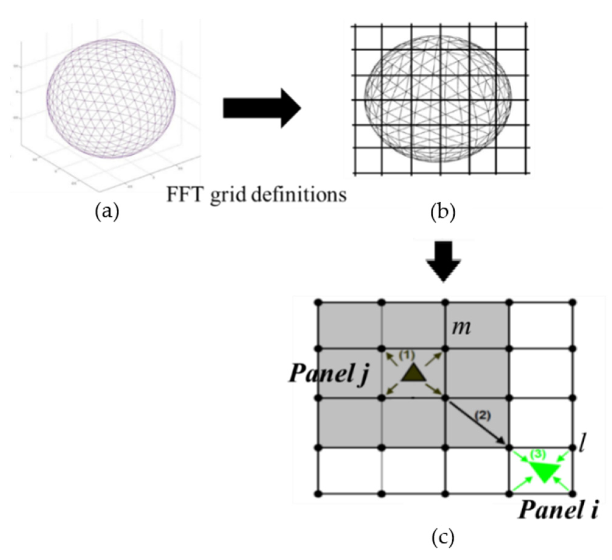
Here, we briefly introduce the PFFT technique. For illustration, we take a radiation sphere as an example in each iteration step of GMRES. As shown in Figure 2a, using the boundary element method, we discretize the surface of the sphere into N small triangular elements with surface sizes of S j , j = 1, …, N. We assume p n is unknown on the sphere surface and we try to evaluate
[ A ] { x } =   j = 1 N i ( p n ) j E j G ( x ; ξ ) d S j ( ξ ) .
In the step of grid definition, we define N g = N x × N y × N z grids in the 3D domain covering the entire surface of the sphere, as shown in Figure 2b. We refer to the cube made up by nearby grids as a cell. Based on a previous study using PFFT [10], the size of the cells h and the elements l are assumed to be the same.
In the step of projection, the normal gradient of the pressure p n at element j is projected to the grids of the cell that contain element j. The formula for projection is
q j m = ( p n ) j E j H m ( ξ ) d S ^ ( ξ ) ,
where Hm is the spatial interpolation function (see, e.g., [10]) for the mth grid of the cell covering element j, and q j m is the strength of the projected ( p n ) j at the mth grid of the cell covering element.
In the step of convolution, we evaluate the total influence at grid point l due to all the projected ( p n ) j at other grids as
( I F s ) l m = m = 0 N g 1 q m G l m ,       l = 0 , 1 , , N g 1 ,
where G l m = 1 | x l ξ m | e i k | x l ξ m | . We note that the summation in Equation (21) is in convolution form and can be computed using FFT with a computation operation of O(Ng log Ng) and a memory requirement of O(Ng).
( I F s ) l m = F F T 1 ( F F T ( q m ) · F F T ( G l ) ) ,   l = 0 , 1 , , N g 1 .
In the step of interpolation, we evaluate the total influence ( I F s ) i j at element i (i = 1, …, N) due to all ( p n ) j using the interpolation function Hm and the grid values ( I F s ) l m . The steps of projection convolution and interpolation are demonstrated in Figure 2c as steps (1)–(3).
It is clear that the accuracy of the interpolation of the influence between elements j and i deteriorates when | x ξ | h = O ( 1 ) or smaller, where h is the size of the cells. In order reduce the error in the near-field, the step of near-field correction is conducted by applying
( I F s ) i j = ( I F s ) i j F F T + ( I F s ) i j ,
where ( I F s ) i j = ( I F s ) i j N ( I F s ) i j N F represents the correction, and ( I F s ) i j N and ( I F s ) i j N F represent the total and near-field influences obtained by direct calculation and the convolution method. Based on earlier studies (e.g., [10]), the size of the near field used in the present study was chosen to be equal to 3 h , which has been shown to be accurate.
In summary, the evaluation of [A]{x} by the PFFT algorithm involves computational efforts of O(N), O(N), O(Nglog Ng), O(N), and O(N) in the steps of grid definition, projection, convolution, interpolation, and near-field correction, respectively. The total computational cost of PFFT-BEM algorithm is thus O(Nlog N).
Other properties of our PFFT-BEM method include (i) a mesh-neighbor (MN) preconditioner for fast iterative convergence (2+ orders faster than the solver without a preconditioner) [16] and (ii) a high performance library PETSC [17] to optimize the implementation of the PFFT-BEM on massive parallel HPC platforms to achieve linear CPU scalability up to O(1000) CPUs. The details of these properties are omitted here and can be found in [16,17].

3. Validation of Multi-Layer PFFT-BEM Solutions

In this section, we first demonstrate the correctness and efficacy of PFFT-BEM by existing benchmark solutions by an ideal waveguide shown in Figure 3. Both the top and bottom boundary satisfy pressure release boundary condition with no bottom layer. The sound source is at a depth of 36 m with frequency at 20 Hz. The other water properties of the waveguide are shown in Figure 3. The computational domain size spans 3 km × 3 km × 100 m with uniform meshing on both the top and bottom surfaces using l = λ/12.
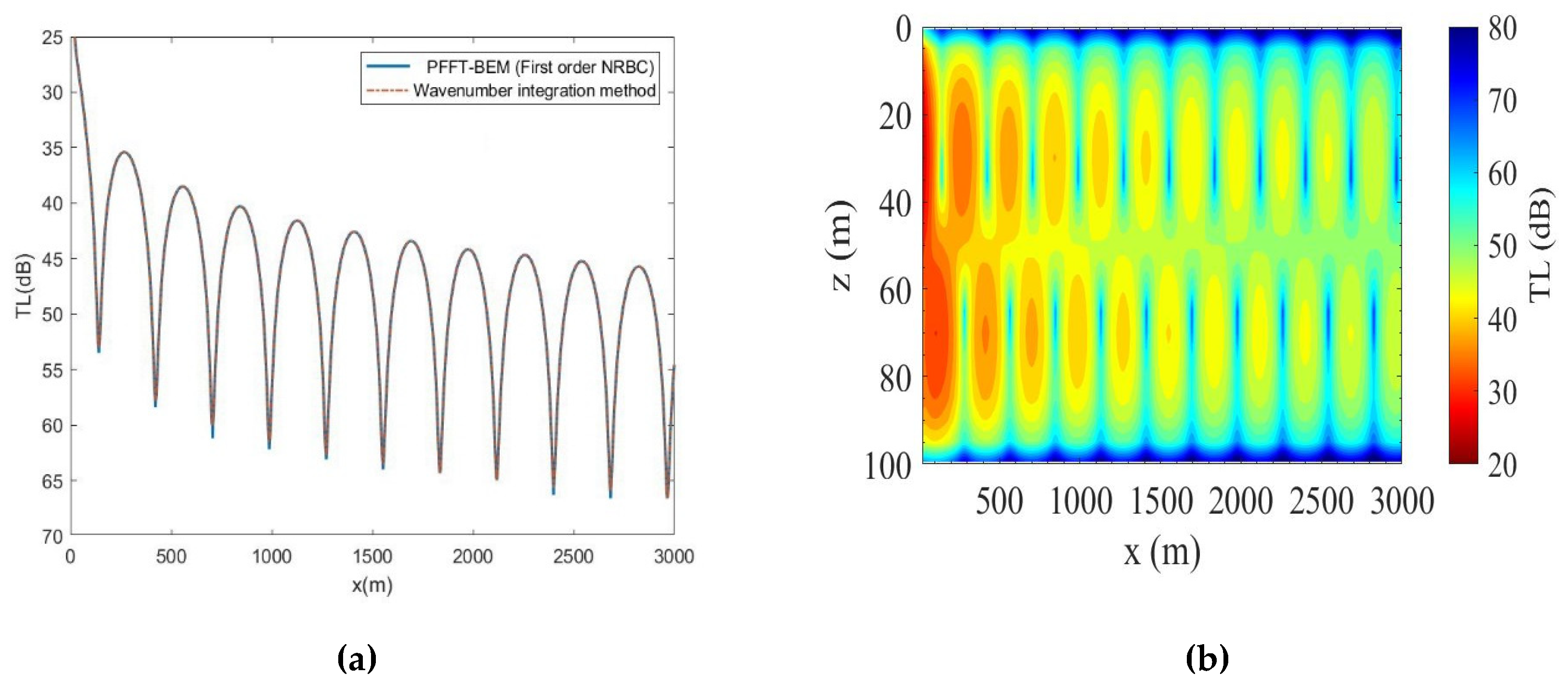
From the comparison shown in Figure 4a, the transmission loss (TL) results of PFFT-BEM show good agreement with ones of the wavenumber integration method, which validates the accuracy of PFFT-BEM. The transmission loss (TL) contour obtained by PFFT-BEM in the x–z plane is shown in Figure 4b.
In Figure 5, we show the convergence of the numerical results towards the wavenumber integration method results with respect to the boundary element size. We compare the acoustical pressure p P F F T B E M by PFFT-BEM with p w i m from wavenumber integration method at z = 36   m . The errors shown in Figure 5 are defined in Equations (24) and (25). As shown in Figure 5, PFFT-BEM results converge clearly towards the wavenumber integration method solution as the element size decreases.
A v e r a g e   e r r o r = a v e r a g e ( p P F F T B E M p w i m p t h e o r y ) ,
M a x   e r r o r = m a x ( p P F F T B E M p w i m p t h e o r y ) .
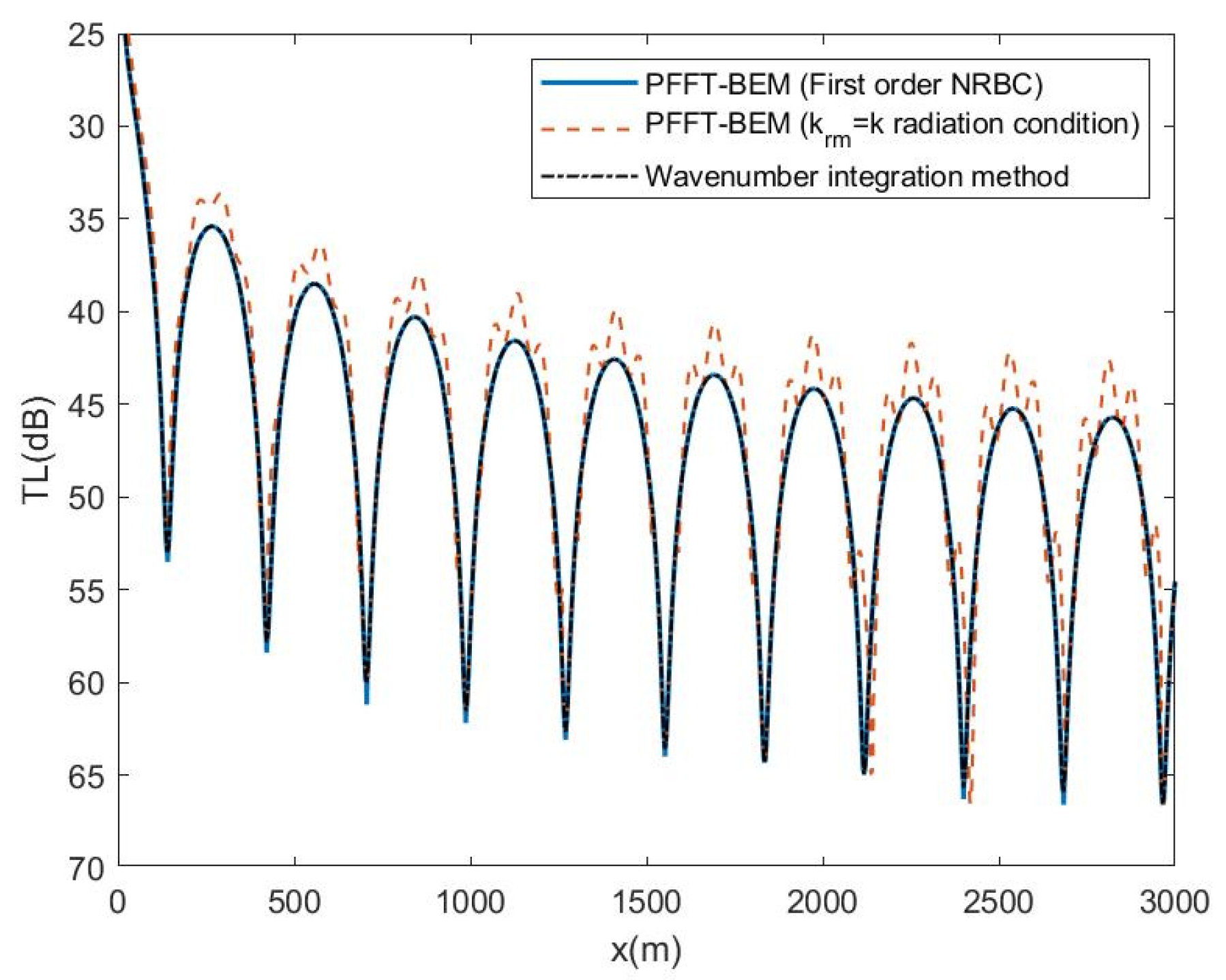
We then check the efficiency of the first-order NRBC at the truncated numerical domain boundary. As shown in Figure 6, PFFT-BEM results clearly improve towards the wave integration method results after radiation condition at the numerical boundary is changed from krm = k radiation condition (Equation (16)) to first-order NRBC (Equation (12)) with m = 2. In addition, the errors of numerical results using the krm = k radiation condition become progressively larger near the truncated domain boundary. When the first order NRBC is used, there are no errors due to the boundary reflection which demonstrate the effectiveness of the first-order NRBCs used by PFFT-BEM for shallow water environments.
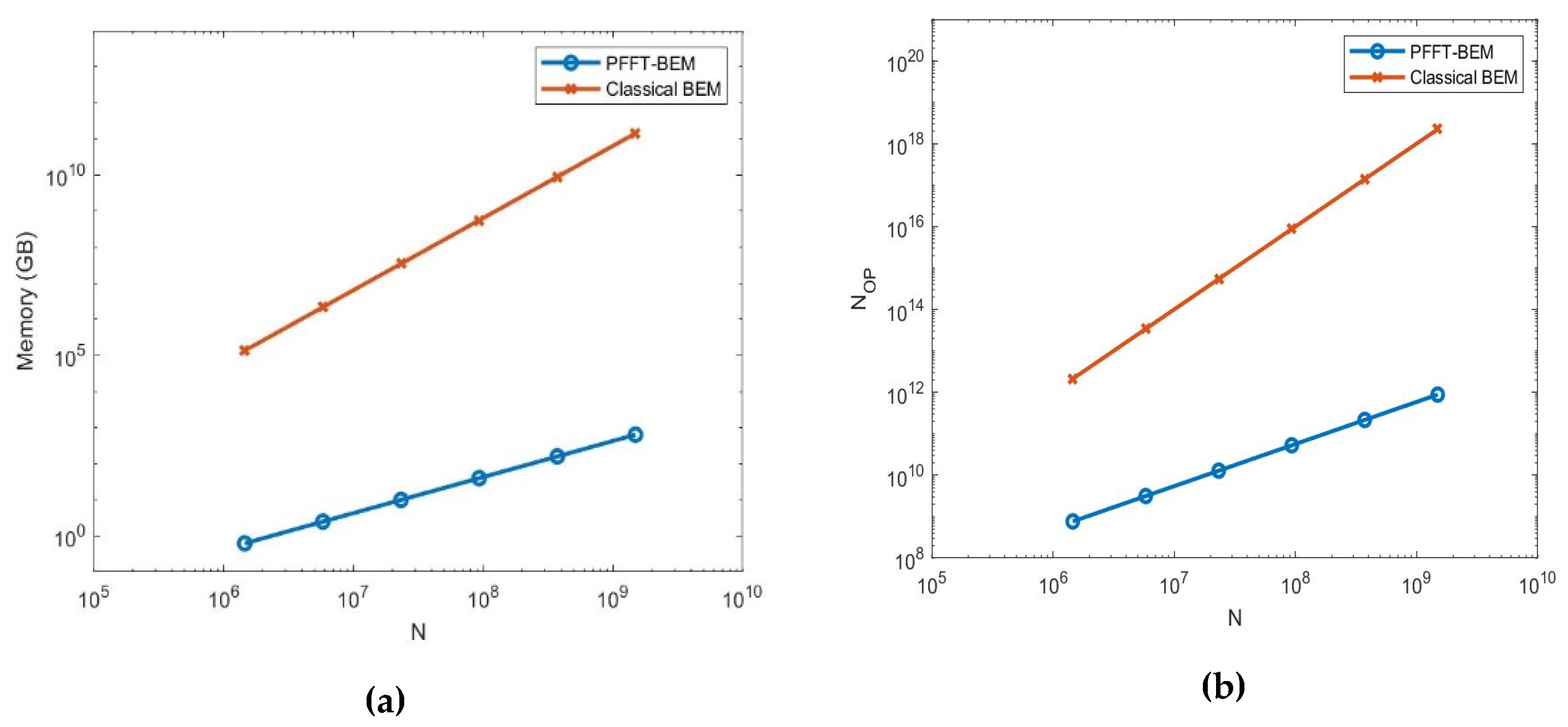
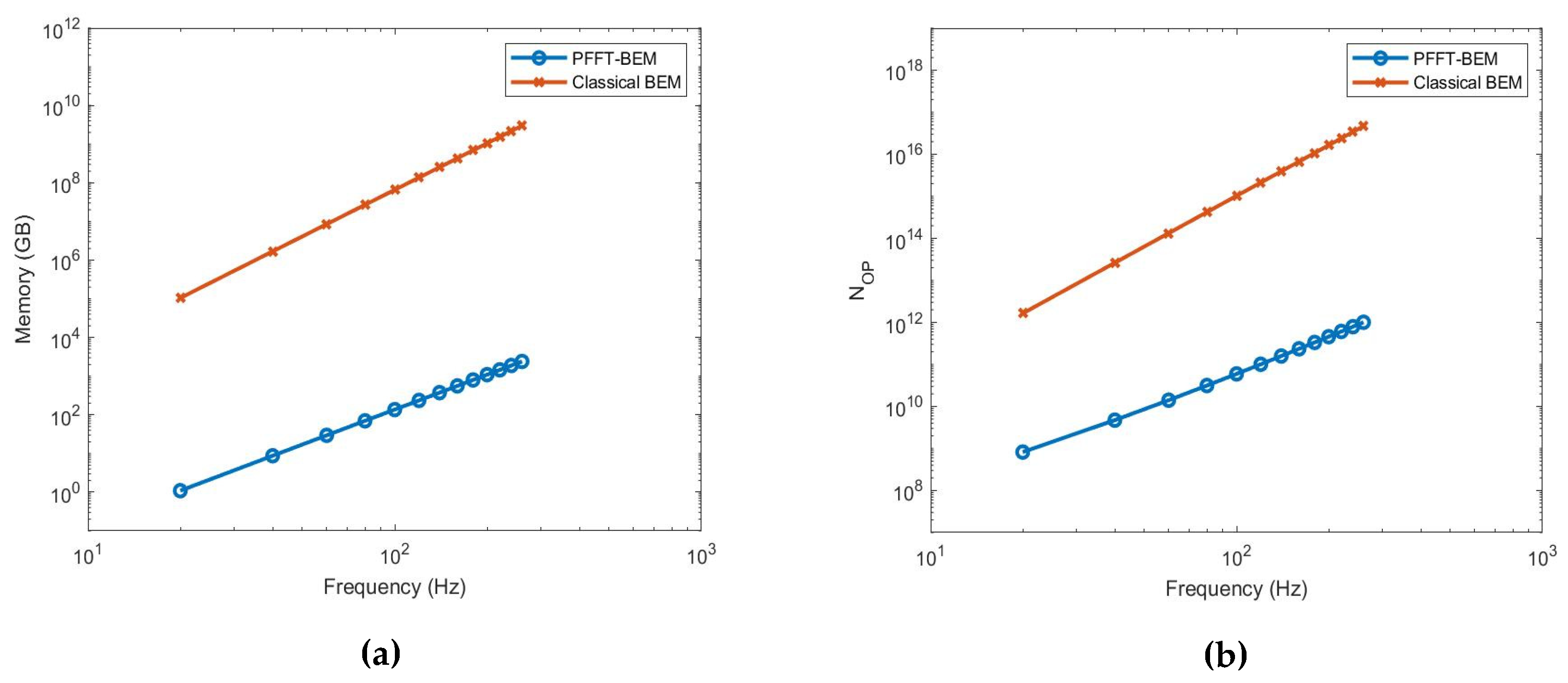
To demonstrate the computational efficiency of the PFFT-BEM, we vary the boundary element size to increase the number of N. As shown in Figure 7, both the memory and operational count of PFFT-BEM are proportional to O(N) and much smaller than the ones of the classical BEM, which is proportional to O ( N 2 ) . This result shows the computational advantage of the PFFT-BEM over the classical BEM for shallow water acoustic simulations. For higher sound source frequency (i.e., smaller acoustics wavelength), the computational cost, which is larger due to the element size, must be much smaller than the acoustics wavelength throughout the entire domain surface. From Figure 8, we show that the PFFT-BEM memory and computational cost is proportional to the sound frequency while it is also much smaller than classical BEM.
In Figure 9, we show the convergence of the numerical results with respect to the number of layers used in the PFFT-BEM. The sound profiles with different gradients, which are used for the convergence tests, are shown in Figure 9a. We compare the averaged difference of the acoustic pressure at z = 36 m between with I layers ( p I ) in the water column and I + 1 layers ( p I + 1 ) in the water column. The difference used for comparison is defined in Equation (26).
Figure 9b shows that the numerical results converge when the number of layers increases. This result demonstrates that the PFFT-BEM can be used for shallow water environments with inhomogeneous sound profiles:
D i f f e r e n c e = a v e r a g e ( | p I p I + 1 | p I + 1 ) .
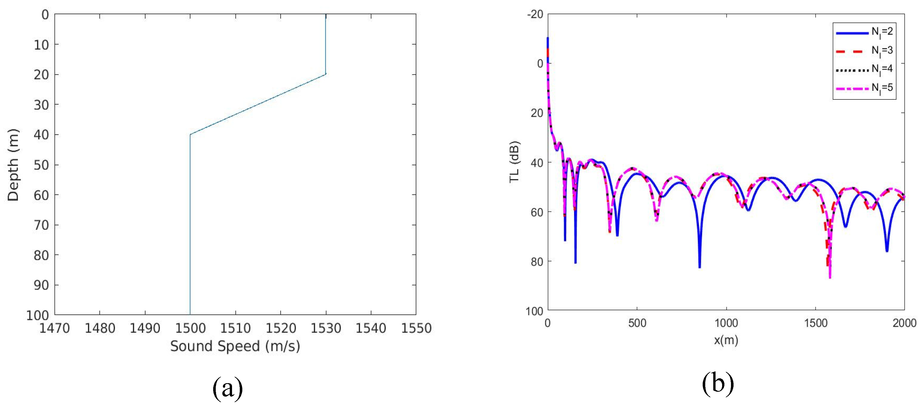
We then demonstrate the use of the PFFT-BEM to realistic range dependent underwater acoustics problems. The same waveguide geometry is used but with the summer sound profile from [18]. The bottom is homogeneous with sound speed 1700 m/s, density 1.5 g/cm3 and medium attenuation α = 0.5 dB/λ. Figure 10a shows the spatial variations of sound speed in the water column. The sound frequency is 60Hz located at 70 m below the sea surface. The computational domain is 2 km × 2 km × 100 m. The boundary element model consists of uniform quadrilateral element with ∆l equals to λ/8. The numerical method computes the transmission loss (TL) along the range at depth of at z = 70 m. Since no theoretical results are available for validation, we show the convergence of the numerical results with respect to the number of layers used in PFFT-BEM. We consider four cases with different number of layers: (i) in the two-layer case, the sound speed is 1500 m/s in z = 0–100 m region and 1700 m/s in z > 100 m region. (ii) In the three-layer case, the sound speed is 1530 m/s in z = 0–30 m region, 1500 m/s in z = 30–100 m region and 1700 m/s in z > 100 m region. (iii) In the four-layer case, the sound speed is 1530 m/s in z = 0–20 m region, 1515 m/s in z = 20–40 m region, 1500 m/s in 40–100 m region and 1700 m/s in z > 100 m region. (iv) In the five-layer case, the sound speed is 1530 m/s in z = 0–20 m region, 1520 m/s in z = 20–30 m region, 1510 m/s in 30–40 m region, 1500 m/s in 40–100 m region and 1700 m/s in z > 100 m region. After five layers are used, Figure 10b shows the numerical results converging with errors only in high TL region. This example demonstrates the use of PFFT-BEM for shallow water environment with inhomogeneous sound profiles.

4. Applications of 3D PFFT-BEM

4.1. Model Comparisons of the PFFT-BEM with the 3D Parabolic Equation Method

To demonstrate the usefulness of PFFT-BEM, PFFT-BEM is compared with 3D Parabolic equation (PE) models to check the correctness and performance of different PE schemes. We first briefly review the formulation and assumptions of the 3D PE theory. Then, we present three numerical examples for comparison: ASA wedge, underwater seamount, and Gaussian canyon.

4.1.1. Formulation and Assumptions of the PE Method

In order to demonstrate the comparison between PFFT-BEM and 3D PE, we briefly describe the formulation of the PE method following previous studies (e.g., [14,19]). We begin with the Helmholtz equation in the frequency domain to determine the acoustic wave pressure p(r) in a cylindrical coordinate system:
p + k 0 2 n 2 p = 0 ,
where k 0 = ω / c 0 is the reference wavenumber, c 0 is the reference sound speed (defined based on the sound profiles [14]), ω is the sound frequency, and n = c 0 /c = k/ k 0 is the index of refraction. The derivation of PE methods in a Cartesian coordinate system is similar to that one in a cylindrical coordinate system and is therefore omitted here. By applying the separation of variables and accounting for only outgoing propagation sound waves, we can approximate p ( r ) by
p ( r ) = H 0 ( k 0 r ) φ ( r , θ , z , ω ) ,
where H 0 is the zeroth-order Hankel function of the first kind. If we assume that there is only outgoing propagation in the range, the Helmholtz equation reduces to an initial boundary value problem governing by a parabolic equation as
φ r = i k 0 ( I + X + Y ) φ ,
with φ ( r = r 0 , θ , z ) = φ 0 ( θ , z ) , where, φ 0 denotes the initial outgoing field at r = r 0 , I is the identity operator, X is the 2D depth operator in the r-z plane, and Y is the azimuthal operator, defined as
X = ( n 2 1 ) I + 1 k 0 z ( 1 ρ z ) ,
Y = 1 ( k 0 r ) 2 2 θ 2 .
Solving Equation (29) usually has a large computational cost. Several methods approximate the nonlinear term (square root operator in Equation (29)) to reduce the computational cost. The 3D PE proposed by Tappert [5] expands the square root operator and only retain the linear terms as
I + X + Y = I + 1 2 ( X + Y ) + O ( X 2 , Y 2 , X Y ) .
It is known that this formulation allows only for narrow angle propagation along θ . For wide angle approximation, Sturm [20] approximates the square root operator using the Pad e ´ approximation along z and a linear approximation long   θ   as
I + X + Y = I + k = 1 n p a k , n p X I + b k , n p X + 1 2 Y + O ( X 2 , Y 2 , X Y ) ,
where np is the number of terms, and a k , n p , b k , n p , 1 k n p are the real coefficients given by
a k , n p = 2 2 n p + 1 s i n 2 ( k π 2 n p + 1 ) ,
b k , n p = c o s 2 ( k π 2 n p + 1 ) .
Another approximation form, which includes part of the nonlinear term, was proposed by Feit and Fleck [21] in a cylindrical coordinate 3D PE method as
ρ k 0 2 z ( 1 ρ z ) + 1 ( k 0 r ) 2 2 θ 2 + n 2 = ρ k 0 2 z ( 1 ρ z ) + 1 ( k 0 r ) 2 2 θ 2 + I + n I .
The numerical results calculated based on these approximations usually have a phase error in the far field [20]. These errors are quantified in the present study by comparison between direct simulation results from PFFT-BEM and results from 3D PE.
Since PE only has one range derivative in the marching direction, it is not possible to enforce both boundary conditions across the vertical boundaries of the marching directions [14]. For most 3D PE methods, only continuity of pressure is enforced across these vertical boundaries. To conserve energy at each marching step, Collins [22] introduced a variable p ˜ = p / ρ c , where c is the sound speed and ρ is the medium density. Then, X and Y shown in Equation (25) can be expressed as
X = ( n 2 1 ) I + ρ k 0 2 ρ c z ( 1 ρ z ) ,
Y = 1 k 0 2 ρ c 2 θ 2 .
However, as indicated by Collins [22], this method tends to overcorrect the solution, and for problems involving a large slope ocean bottom (> 10 ° ), the energy conservation PE error becomes significant.
In summary, three main assumptions are made during the formulation of the 3D PE method:
  • Higher-order term effects: the higher-order terms of the square root operator are small and negligible;
  • Backscattering effects: only forward scattering is included (no backscattering effects);
  • Large slope effects: only pressure continuity is satisfied across the marching vertical boundaries.
As a result, we further demonstrate the differences between 3D direct numerical simulation results by the PFFT-BEM method and 3D PE results due to the assumptions used in 3D PE. To achieve this, we examine three classical shallow water examples: the ASA wedge, 3D underwater seamount, and a Gaussian canyon problem.

4.1.2. Higher-Order Term Effects: Acoustical Society of America (ASA) Wedge

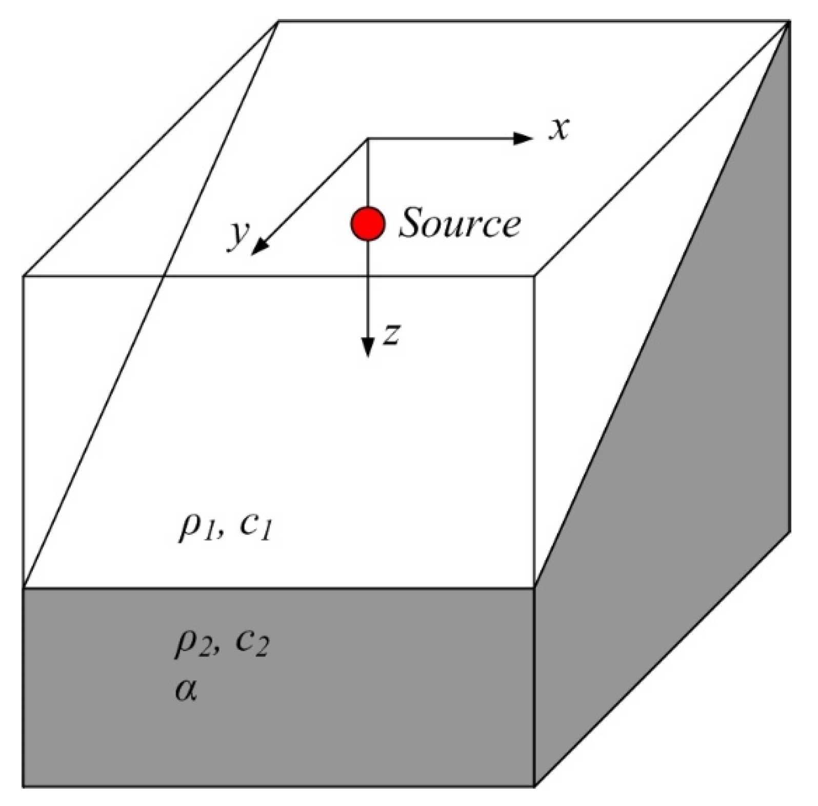
The first benchmark example is the ASA wedge, as shown in Figure 11. The sound source is fixed at (0, 0, 100 m) with a frequency at 75 Hz. The wedge meets free surface (z = 0) at y = –2000 m. The slope angle of the wedge is π /36. The computational domain size covers the range of 28   km × 4   km with a maximum depth at 400 m. The medium properties are defined in Figure 11, with sound speed c 1 = 1500 m/s and density ρ 1   = 1 g/cm3 in the water and c2 = 1700 m/s, density ρ 2 = 1.5 g/cm3 and medium attenuation α = 0.5   dB / λ in the bottom. The boundary element model uses quadrilateral element with l   =   λ /12. We compared the 3D PFFT-BEM with 3D cylindrical coordinate PE results based on the nonlinear operator Equation (32). The far-field solution of 3D PFFT-BEM and a 3D PE method are compared with benchmark solutions. From Figure 12a, quantitative validation of large-scale 3D sound field prediction by direct numerical computation is obtained. In contrast, phase error is observed in the far field of 3D PE results. The approximation of the square root operator in Equation (21) is the main reason for this phase error. Figure 12b shows the phase differences between PFFT-BEM and the 3D PE method. As expected, the phase errors of 3D PE increase as a function of distance. It should be noted that higher-order terms can be included to make the 3D PE solutions more accurate [23,24]. However, the small marching steps of this higher-order 3D PE method will introduce large computational costs, especially in the cylindrical coordinates. We show the 3D feature of the TL contour for the ASA wedge in Figure 13.

4.1.3. Backscattering Effects: 3D Seamount

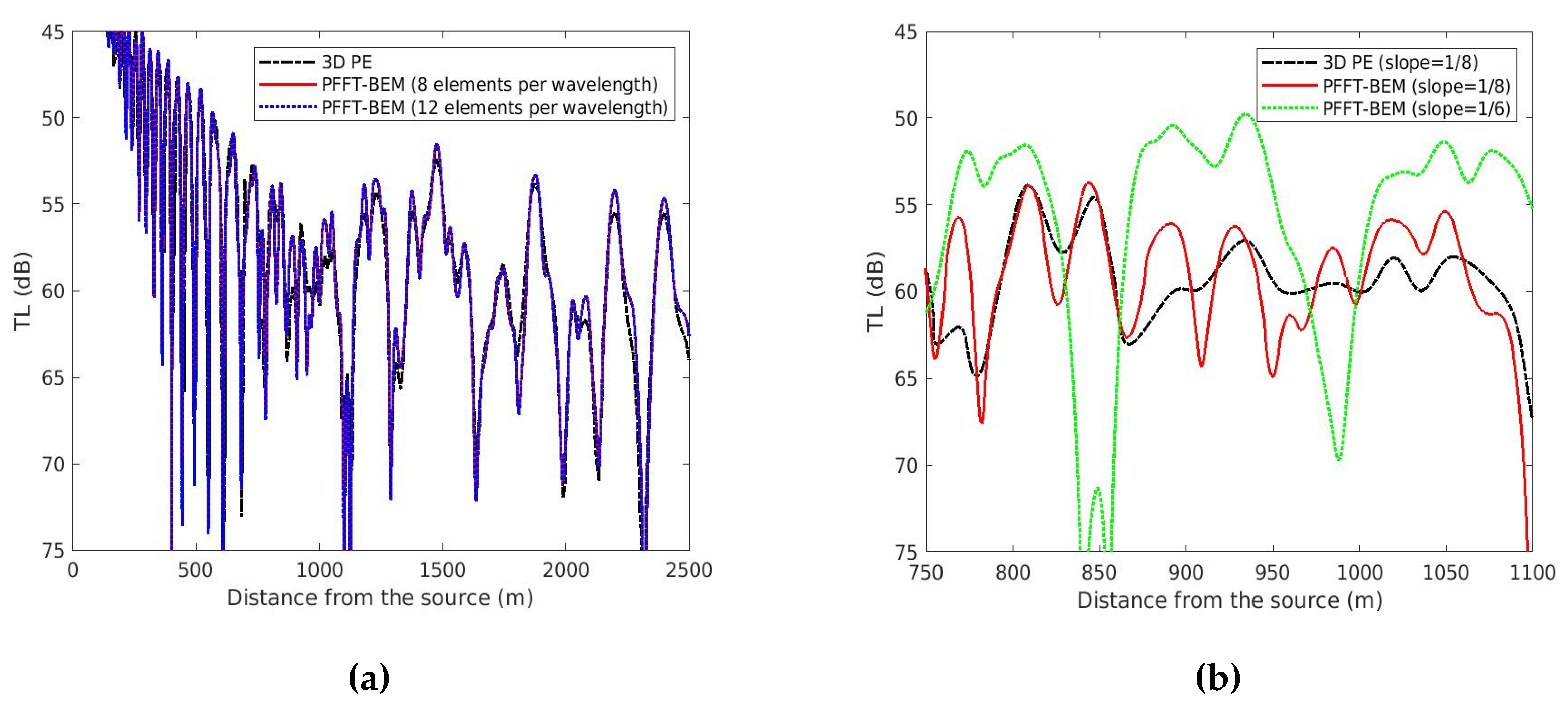
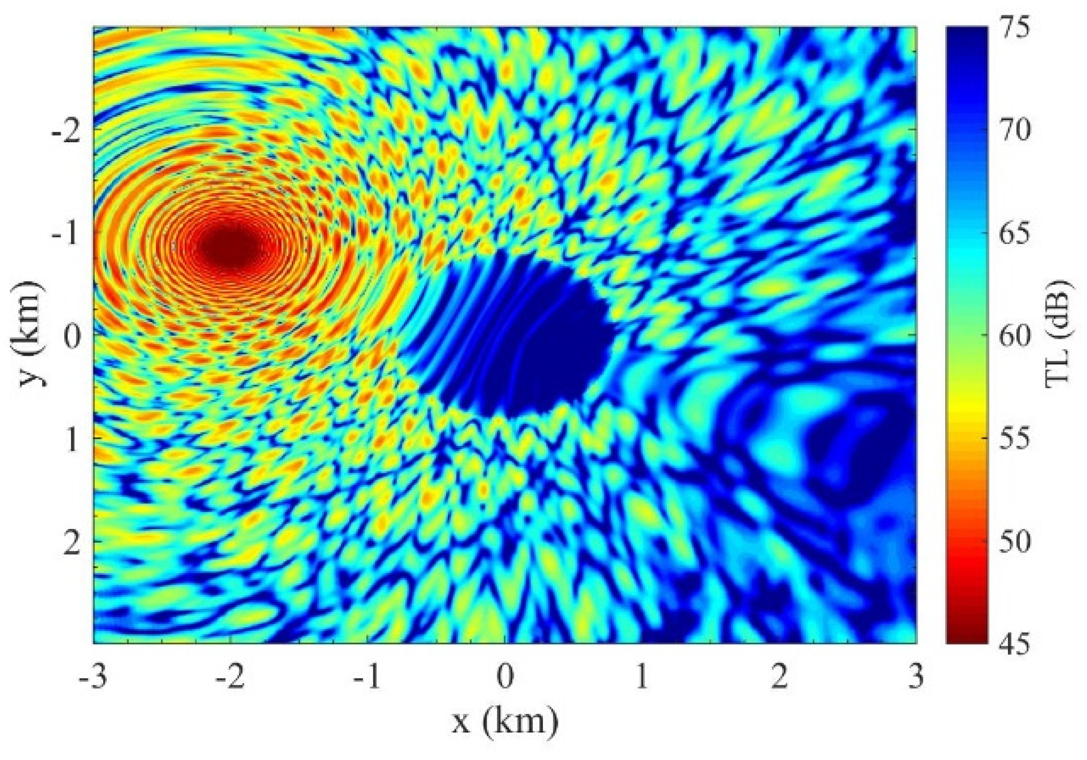
In the second numerical example, we show a comparison of the 3D PFFT-BEM and a 3D PE method for an idealized seamount. The water column is homogeneous with a sound speed of 1500 m/s, a density of 1.0 g/cm3, and no medium absorption for sound waves. The bottom is also homogeneous with a sound speed of 1700 m/s, a density of 1.5 g/cm3, and medium attenuation at 0.5 dB/λ. The origin of the coordinate system is located above the seamount at the sea surface with z pointing down towards the ocean. The 100 Hz sound source in this example is placed away from the tip of the seamount at x = −2000 m, y = 850 m, and z = 250 m. The summit of the seamount is at a depth of 200 m, and its slope is 7. The radius of the seamount is 2500 m, and the water depth outside the seamount area is 512.5 m. Figure 14a compares the 3D PFFT-BEM numerical results of TL to the 3D PE results by [19] along the x−axis at z = 250 m in front of the seamount (2 km away from the source). First, as shown in Figure 14a, convergence is observed with an increase in the element numbers, which demonstrates the accuracy of PFFT-BEM. The difference between 3D PE and PFFT-BEM is more significant in front of the seamount. This difference is mainly due to the backscattering effects, which are not included in the 3D PE. We zoom in on the range from 750 to 1100 m, which is in front of the seamount. As shown in Figure 14b, significant differences between the PFFT-BEM and 3D PE results (3 ∼ 5 dB) are observed. In Figure 14b, we compare the TL along the x-axis for two cases with different slopes (1/6 and 1/8). As expected, the TL is smaller (i.e., larger acoustic pressure) in the larger slope case (1/6), which indicates stronger backscattering effects. Under such conditions, we expect that the errors due to neglecting the backscattering effects are more significant, and the use of a 3D full field method such as PFFT-BEM is more necessary. To demonstrate the 3D scattering effects, we plot Figure 15 to show the TL contour computed by 3D PFFT-BEM.

4.1.4. Large Slope Effects: Gaussian Canyon

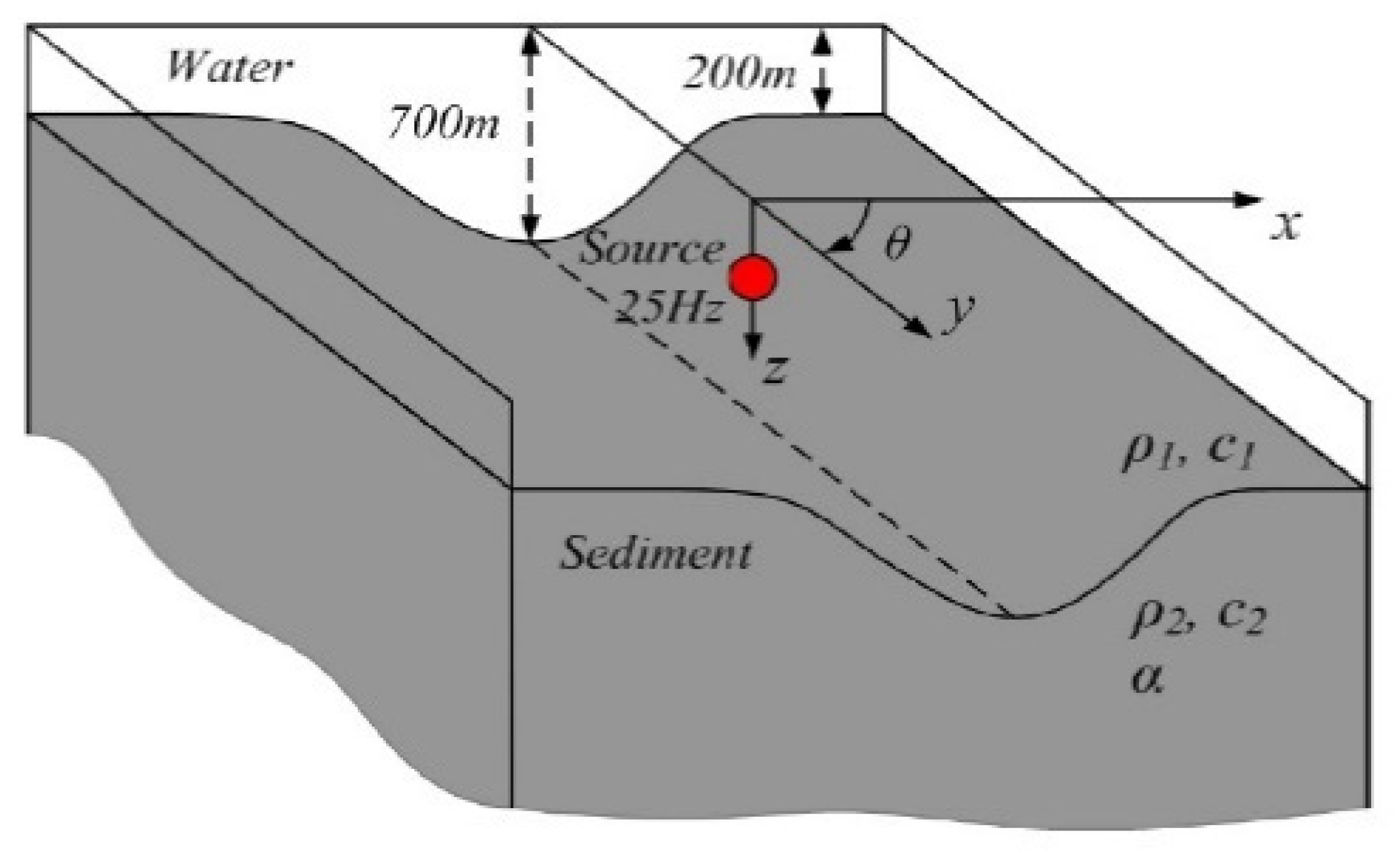
For problems involving an ocean bottom with a very large slope (> 10°), the validity of 3D PE needs to be examined by a direct numerical method. In the next benchmark problem, we consider a waveguide problem with a Gaussian canyon. The water column has a depth of 700 m with c1 = 1500 m/s and ρ1 = 1.0 g/cm3. The sound source has frequency of 25 Hz and is fixed at (0, 0, 30 m). The bottom has the properties of ρ2 = 1.5 g/cm3, c2 = 1700 m/s and medium attenuation α = 0.5 dB/λ. The geometry of the Gaussian canyon bottom is defined as
h ( x ) = h 0 + h 1 e x p ( x 2 σ 2 ) ,
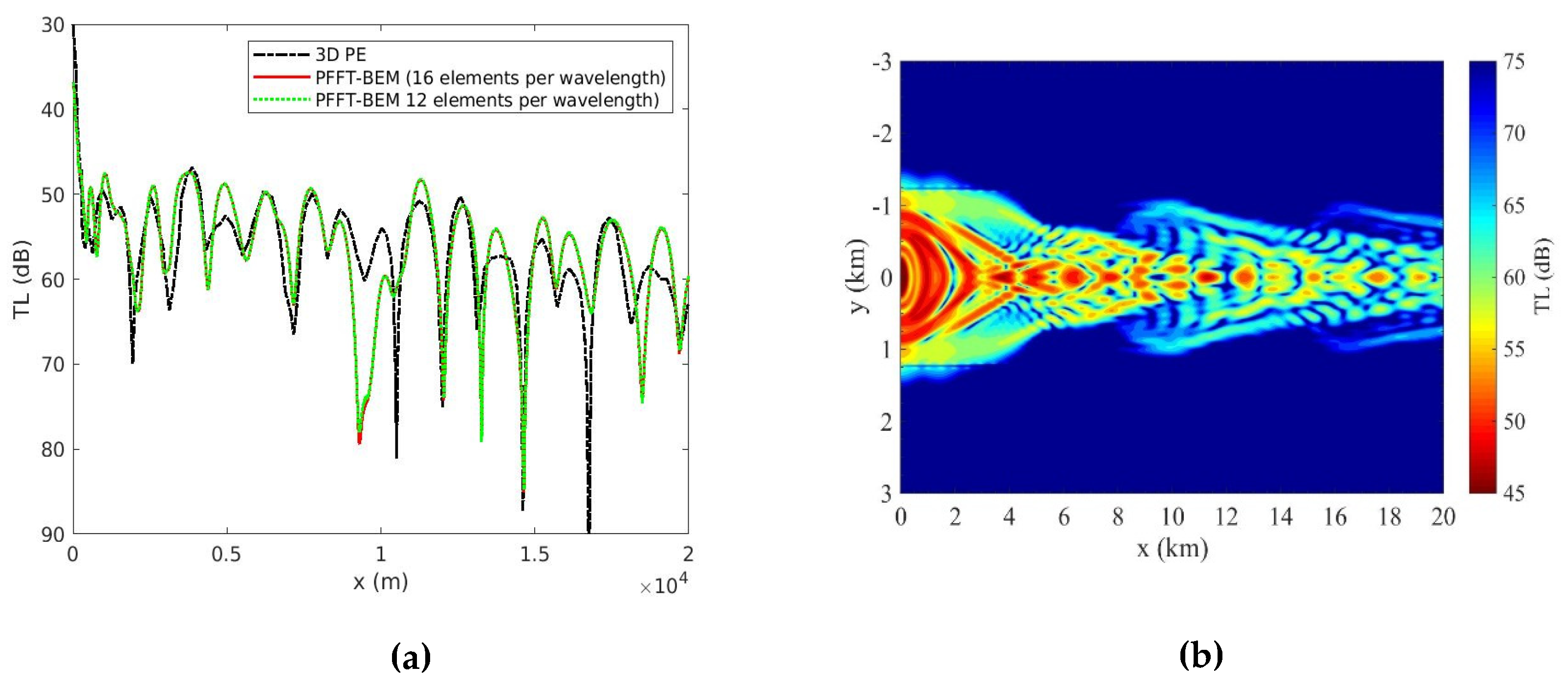
where the parameters are ℎ0 = 20 m, ℎ1 = 180 m, and σ = 720 m. The largest slope in the direction across the canyon is approximately 0.21 (angle of 12.1°). The geometry of the canyon is plotted in Figure 16. We compare the 3D PFFT-BEM solution along the canyon with the 3D cylindrical coordinate PE results from [20]. As shown in Figure 17a, numerical convergence of PFFT-BEM is observed with increasing element numbers. This proves the accuracy of the PFFT-BEM. In Figure 17a, differences (∼ 8 dB) between the 3D PE and 3D PFFT-BEM can be observed in energy-focusing regions along the canyon axis where horizontal refractions by the sidewalls of the canyon are the strongest (shown in Figure 17b). These differences are mainly due to the fact that, for 3D PE, only one of the two boundary continuity conditions can be satisfied in the marching direction. As a result, for environment geometries with large slopes in the marching directions, such as this Gaussian canyon, the 3D PE method becomes inaccurate and deviates from the direct numerical solutions by PFFT-BEM. We also show the contours of the transmission loss in Figure 17b where strong 3D scattering effects from the canyon are observed.

4.2. Prediction of Sound Scattering by Traveling Internal Waves

Tidal interactions with bottom features often generate internal solitary waves (ISWs) in a shallow water environment. Previous experiments [26,27,28] found that acoustic signals fluctuate when sound waves are transmitted through ISWs. The amplitudes and phases of these fluctuations are highly correlated with those of ISWs. Quantifying the interactions between the acoustic waves and ISWs is important for shallow acoustics. Here, we compare our numerical simulation of sound propagate through ISW with the experiment data from SWRAM’95 (shallow-water acoustics in a random medium) which is conducted in the New Jersey continental shelf in 1995. The experiment setup and data are presented in detail by previous studies [26,27,28,29,30]. The purpose of including this example is to demonstrate the capability of using large-scale direct simulations in the prediction of acoustic scattering by internal waves, which is critically needed in shallow water acoustics.
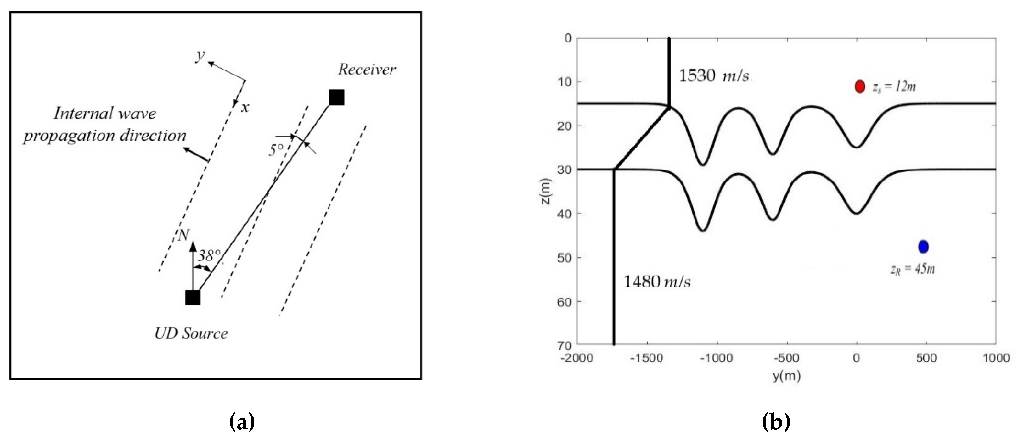
We plot the positions of the source, receiver and ISWs fronts during experiment in Figure 18a. During the interval 18:00 to 20:00 GMT on 4 August 1995, the source is fixed at zs = 12 m below the sea surface at the position approximately 15 km from the receiver, as shown in Figure 18b [28]. The receiver is placed at zR = 45 m below the sea surface. The broadband source frequency f   was 30~160 Hz with three peak frequencies at 30, 60, and 90 Hz.
Using the PFFT-BEM, we simulate the propagation of the acoustic waves through the internal waves. As shown in Figure 18b, a soliton wave packet model based on Duda and Preisig [31] is used in the 3D PFFT-BEM direct numerical simulation. The properties of the water column and sea bottom are shown in Figure 18b. To consider the change in the sound speed, we use four layers in the gradient region where the sound speed changes from 1530 to 1480 m/s. The properties of the bottom are cb = 1750 m/s, ρ b   = 1.8 g/cm3 with an attenuation parameter of α = 0.4375   dB/λ. The velocity of the ISWs (in the y direction) is 0.65 m/s. Here, we ignore the differences between the speeds of separate solitary waves. As a result, the entire internal wave train is assumed to move at the same speed. The sound source frequencies used in the 3D PFFT-BEM are 30, 60 and 90 Hz.
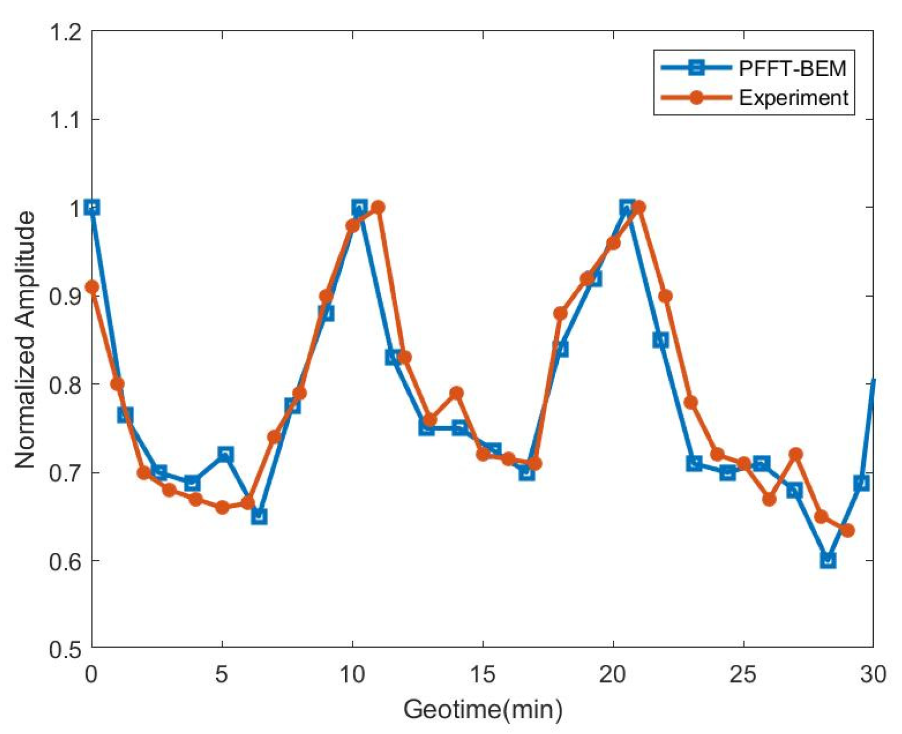
To demonstrate the accuracy of PFFT-BEM in simulating the acoustical scattering effects by the internal waves, we compare the acoustic pressure calculated using the 3D PFFT-BEM at the receiver with the field measurement during a 30 min period [28]. As shown in Figure 19, the numerical prediction by the PFFT-BEM agrees fairly well with the field experimental data for the time variation trend and the magnitude of the fluctuation of the received sound pressure. The difference is mainly because the internal waves are irregular during the experiment, while the regular wave model is used in our PFFT-BEM numerical model. The root mean square between the numerical prediction and experimental data is 3 %. For underwater sound measurements, the uncertainty of the receiver system in field conditions is approximately 0.5 dB [32]. As a result, a relative error of 3 % (i.e., 0.13 dB) would be sufficient for the underwater acoustic numerical simulation.

5. Conclusions

We have presented an efficient boundary element method with a multi-layer formulation and first-order non-reflecting boundary condition for the simulation of sound propagation in a shallow water environment. By using the pre-corrected fast Fourier transform method, the developed method, PFFT-BEM, which reduces the computational cost from O(N2) to O(Nlog N), can be applied to the 3D full-field direct numerical simulation of sound propagation in environments with a sound frequency of up to O(100) Hz and a domain size of up to O(10) km. We found that the developed multi-layer numerical method is capable to simulate the sound propagation in inhomogeneous waveguide accurately. We also concluded that the first-order NRBC used in PFFT-BEM can efficiently eliminate the errors due to reflection from artificial numerical boundary. We demonstrated the usefulness of the developed PFFT-BEM for shallow water acoustic applications. First, the 3D direct numerical simulation capability of PFFT-BEM enable us to check the validity of classical approximation models. We show the evaluation of the 3D PE models for three examples: the ASA wedge, the 3D seamount, and the Gaussian canyon. Through these comparisons, we demonstrated and quantified the differences between 3D direct numerical simulation results by PFFT-BEM and 3D PE results due to the main assumptions used in the 3D PE. To show the usefulness of the PFFT-BEM in real applications, we compared the numerical results obtained by the 3D+T PFFT-BEM and the field measurement data from the SWARM’ 95 internal wave experiment. The transmission loss obtained with the PFFT-BEM showed strong variability as the internal wave train moved. The magnitude and trend of these numerical variations agree fairly well with the field experiments. This indicates that the 3D+T PFFT-BEM is applicable for the direct simulation of sound propagation in a complex 3D shallow water environment. We concluded that the developed direct numerical method, PFFT-BEM, is very useful to quantify the accuracy of exiting numerical methods and simulate sound propagation in realistic multi-layer shallow water environments.

Author Contributions

Conceptualization, C.L.; methodology, C.L.; software, C.L.; validation, C.L.; formal analysis, C.L.; investigation, C.L.; resources, C.L.; data curation, C.L.; writing—original draft preparation, C.L.; writing—review and editing, J.L.; All authors have read and agreed to the published version of the manuscript.

Funding

This research was partially supported by the Office of Naval Research (N00014-16-1-2200) and was granted access to the HPC re-sources provided by the DOD HPC Modernization Program.

Conflicts of Interest

The authors declare no conflict of interest.

References

  1. Luo, W.; Schmidt, H. Three-dimensional propagation and scattering around a conical seamount. J. Acoust. Soc. Am. 2009, 125, 52–65. [Google Scholar] [CrossRef] [Green Version]
  2. Taroudakis, M.I. A coupled-mode formulation for the solution of the Helmholtz equation in water in the presence of a conical seamount. J. Comput. Acoust. 1996, 4, 101–121. [Google Scholar] [CrossRef]
  3. Shmelev, A.A.; Lynch, J.F.; Lin, Y.-T.; Schmidt, H. Three-dimensional coupled mode analysis of internal-wave acoustic ducts. J. Acoust. Soc. Am. 2014, 135, 2497–2512. [Google Scholar] [CrossRef] [Green Version]
  4. Porter, M.B. The Bellhop Manual and User’s Guide: Preliminary Draft; Heat, light, and Sound Res. Inc.: La Jolla, CA, USA, 2011. [Google Scholar]
  5. Tappert, F.D. The parabolic approximation method. In Wave Propagation and Underwater Acoustics; Springer: Berlin/Heidelberg, Germany, 1977; pp. 224–287. [Google Scholar]
  6. Lingevitch, J.F.; Collins, M.D.; Mills, M.J.; Evans, R.B. A two-way parabolic equation that accounts for multiple scattering. J. Acoust. Soc. Am. 2002, 112, 476–480. [Google Scholar] [CrossRef] [PubMed]
  7. Collins, M.D.; Evans, R.B. A two-way parabolic equation for acoustic backscattering in the ocean. J. Acoust. Soc. Am. 1992, 91, 1357–1368. [Google Scholar] [CrossRef]
  8. Zhu, D.; Bjørnø, L. A three-dimensional, two-way, parabolic equation model for acoustic backscattering in a cylindrical coordinate system. J. Acoust. Soc. Am. 2000, 108, 889–898. [Google Scholar] [CrossRef] [PubMed] [Green Version]
  9. Phillips, J.R.; White, J.K. A precorrected-FFT method for electrostatic analysis of complicated 3-D structures. IEEE Trans. Comput. Aided Des. Integr. Circuits Syst. 1997, 16, 1059–1072. [Google Scholar] [CrossRef] [Green Version]
  10. Yan, H.; Liu, Y. An efficient high-order boundary element method for nonlinear wave–wave and wave-body interactions. J. Comput. Phys. 2011, 230, 402–424. [Google Scholar] [CrossRef]
  11. Li, C.; Campbell, B.K.; Liu, Y.; Yue, D.K. A fast multi-layer boundary element method for direct numerical simulation of sound propagation in shallow water environments. J. Comput. Phys. 2019, 392, 694–712. [Google Scholar] [CrossRef]
  12. Bayliss, A.; Turkel, E. Radiation boundary conditions for wave-like equations. Commun. Pure Appl. Math. 1980, 33, 707–725. [Google Scholar] [CrossRef]
  13. Givoli, D. High-order local non-reflecting boundary conditions: A review. Wave Motion 2004, 39, 319–326. [Google Scholar] [CrossRef]
  14. Jensen, F.B.; Kuperman, W.A.; Porter, M.B.; Schmidt, H. Computational Ocean Acoustics; Springer Science & Business Media: Berlin/Heidelberg, Germany, 2011. [Google Scholar]
  15. Vendhan, C.P.; Diwan, G.C.; Bhattacharyya, S.K. Finite-element modeling of depth and range dependent acoustic propagation in oceanic waveguides. J. Acoust. Soc. Am. 2010, 127, 3319–3326. [Google Scholar] [CrossRef] [PubMed]
  16. Harris, P.J.; Chen, K. On efficient preconditioners for iterative solution of a Galerkin boundary element equation for the three-dimensional exterior Helmholtz problem. J. Comput. Appl. Math. 2003, 156, 303–318. [Google Scholar] [CrossRef] [Green Version]
  17. Balay, S.; Abhyankar, S.; Adams, M.; Brown, J.; Brune, P.; Buschelman, K.; Dalcin, L.; Dener, A.; Eijkhout, V.; Gropp, W.; et al. PETSc Users Manual; Technical Report for Argonne National Laboratory: Alexandra, VA, USA, 2019.
  18. Kuperman, W.A.; Lynch, J.F. Shallow-water acoustics. Phys. Today 2004, 57, 55–61. [Google Scholar] [CrossRef]
  19. Lin, Y.-T.; Duda, T.F.; Newhall, A.E. Three-dimensional sound propagation models using the parabolic-equation approximation and the split-step Fourier method. J. Comput. Acoust. 2013, 21, 1250018. [Google Scholar] [CrossRef] [Green Version]
  20. Sturm, F. Numerical study of broadband sound pulse propagation in three-dimensional oceanic waveguides. J. Acoust. Soc. Am. 2005, 117, 1058–1079. [Google Scholar] [CrossRef] [Green Version]
  21. Feit, M.; Fleck, J. Light propagation in graded-index optical fibers. Appl. Opt. 1978, 17, 3990–3998. [Google Scholar] [CrossRef]
  22. Collins, M.D. An energy-conserving parabolic equation for elastic media. J. Acoust. Soc. Am. 1993, 94, 975–982. [Google Scholar] [CrossRef]
  23. Lin, Y.-T.; Collis, J.M.; Duda, T.F. A three-dimensional parabolic equation model of sound propagation using higher-order operator splitting and Padé approximants. J. Acoust. Soc. Am. 2012, 132, EL364–EL370. [Google Scholar] [CrossRef] [Green Version]
  24. Sturm, F. Leading-order cross term correction of three-dimensional parabolic equation models. J. Acoust. Soc. Am. 2016, 139, 263–270. [Google Scholar] [CrossRef]
  25. Deane, G.; Buckingham, M. An analysis of the three-dimensional sound field in a penetrable wedge with a stratified fluid or elastic basement. J. Acoust. Soc. Am. 1993, 93, 1319–1328. [Google Scholar] [CrossRef]
  26. Apel, J.R.; Badiey, M.; Chiu, C.-S.; Finette, S.; Headrick, R.; Kemp, J.; Lynch, J.F.; Newhall, A.; Orr, M.H.; Pasewark, B.H.; et al. An overview of the 1995 SWARM shallow-water internal wave acoustic scattering experiment. IEEE J. Ocean. Eng. 1997, 22, 465–500. [Google Scholar] [CrossRef]
  27. Headrick, R.H.; Lynch, J.F.; Kemp, J.N.; Newhall, A.E.; von der Heydt, K.; Apel, J.; Badiey, M.; Chiu, C.; Finette, S.; Orr, M.; et al. Acoustic normal mode fluctuation statistics in the 1995 SWARM internal wave scattering experiment. J. Acoust. Soc. Am. 2000, 107, 201–220. [Google Scholar] [CrossRef] [PubMed]
  28. Badiey, M.; Katsnelson, B.G.; Lynch, J.F.; Pereselkov, S.; Siegmann, W.L. Measurement and modeling of three-dimensional sound intensity variations due to shallow-water internal waves. J. Acoust. Soc. Am. 2005, 117, 613–625. [Google Scholar] [CrossRef] [PubMed] [Green Version]
  29. Headrick, R.H. Analysis of Internal Wave induced Mode Coupling Effects on the 1995 SWARM Experiment Acoustic Transmissions; Woods Hole Oceanographic Institution MA: Woods Hole, MA, USA, 1997. [Google Scholar]
  30. Shmelev, A.A. Three-Dimensional Acoustic Propagation through Shallow Water Internal, Surface Gravity and Bottom Sediment Waves. Ph.D. Thesis, Massachusetts Institute of Technology Joint Program in Applied Ocean Science, Cambridge, MA, USA, September 2011. [Google Scholar]
  31. Duda, T.F.; Preisig, J.C. A modeling study of acoustic propagation through moving shallow-water solitary wave packets. IEEE J. Ocean. Eng. 1999, 24, 16–32. [Google Scholar] [CrossRef] [Green Version]
  32. Robinson, S.P.; Lepper, P.A.; Hazelwood, R.A. Good Practice Guide for Underwater Noise Measurement; Technical Report for National Physics Laboratory: Teddington, UK, March 2014. [Google Scholar]
Figure 1. Schematic of the multilayer model with a total number of layers of I = 3.
Applsci 10 02393 g001
Figure 2. Demonstration of the grid definition, projection, convolution, and interpolation of the pre-corrected fast Fourier transform (PFFT)-boundary element method (BEM) numerical scheme. (a) boundary element mesh; (b) fast Fourier transform (FFT) grid definition over the element mesh; (c) demonstration of (1) projection, (2) convolution, and (3) interpolation.
Applsci 10 02393 g002
Figure 3. Sketch of the iso-velocity waveguide.
Applsci 10 02393 g003
Figure 4. (a) TL at z = 36 m obtained by PFFT-BEM and wavenumber integration method (chapter 4 of [14]); (b) TL contour obtained by PFFT-BEM.
Applsci 10 02393 g004
Figure 5. Numerical errors of PFFT-BEM for acoustics pressure at z = 36 m as functions of elements per wavelength.
Applsci 10 02393 g005
Figure 6. Transmission Loss (TL) at z = 36m for a 20 Hz point source at a depth of 36 m in the iso-velocity waveguide: comparison of the PFFT-BEM with the krm = k radiation condition, PFFT-BEM with first-order NRBC.
Applsci 10 02393 g006
Figure 7. Comparison of the PFFT-BEM (slope 1) and classical BEM (slope 2) for the iso-velocity waveguide. (a) Memory (GB); (b) operational counts.
Applsci 10 02393 g007
Figure 8. Frequency dependence of PFFT-BEM computational performance: (a) memory and (b) operational counts.
Applsci 10 02393 g008
Figure 9. (a) Sound profiles used in the convergence tests; (b) normalized average difference of acoustic pressure at z = 36 m obtained using the PFFT-BEM as a function of number of layers used in the water column.
Applsci 10 02393 g009
Figure 10. (a) Shallow water summer sound profile with a gradient region at 20–40 m; (b) transmission loss (TL) in the waveguide with summer sound profile: comparison among PFFT-BEM results with different number of layers (N i).
Applsci 10 02393 g010
Figure 11. Sketch of the ASA wedge.
Applsci 10 02393 g011
Figure 12. (a) TL in the far field along the x-axis at z = 30 m for ASA wedge: comparison among 3D PFFT-BEM, benchmark results [25] and a 3D PE model results; (b) phase differences between 3D PFFT-BEM direct simulation and a 3D PE model results as a function of distance from the source.
Applsci 10 02393 g012
Figure 13. TL contour at z = 30 m obtained by PFFT-BEM.
Applsci 10 02393 g013
Figure 14. (a) TL along the x-axis at z = 250 m for the conical seamount: comparison between 3D direct simulations by PFFT-BEM and 3D PE by [19]; (b) TL along the x-axis at z = 250 m for the conical seamount: comparison between cases with seamount slopes of 1/6 and 1/8 from PFFT-BEM and a seamount slope of 1/8 from 3D PE.
Applsci 10 02393 g014
Figure 15. TL contour at z = 250 m obtained by 3D PFFT-BEM.
Applsci 10 02393 g015
Figure 16. The geometry of the Gaussian canyon used in the present study with an upper water layer with ρ1 = 1 g/cm3, c1 = 1500 m/s on top of a soil bottom with ρ2 = 1.5 g/cm3, c2 = 1700 m/s, and medium attenuation of α = 0.5 dB/λ.
Applsci 10 02393 g016
Figure 17. (a) TL along the canyon axis at z = 30 m for the Gaussian canyon: comparison between 3D direct simulations by PFFT-BEM and 3D PE by Sturm [20]; (b) TL obtained using PFFT-BEM on the horizontal plane at z = 30 m of the Gaussian canyon.
Applsci 10 02393 g017
Figure 18. (a) Field experimental arrangement of the source/receiver and their relative positions with respect to the internal wave fronts; (b) parameters of the PFFT-BEM simulation.
Applsci 10 02393 g018
Figure 19. Comparison of field normalized acoustic pressure data and normalized acoustic pressure predicted by the PFFT-BEM.
Applsci 10 02393 g019