Article

Improving the Performance of EDM through Relief-Angled Tool Designs

by
Nadeem Ahmad Mufti
1,
Madiha Rafaqat
1,
Naveed Ahmed
1,2,*,
Muhammad Qaiser Saleem
1,
Amjad Hussain
1 and
Abdulrahman M. Al-Ahamri
3
1
Department of Industrial and Manufacturing Engineering, University of Engineering and Technology, Lahore 54890, Pakistan
2
Department of Industrial Engineering, College of Engineering and Architecture, Al Yamamah University, Riyadh 11512, Saudi Arabia
3
Raytheon Chair for Systems Engineering, Advanced Manufacturing Institute, King Saud University, Riyadh 11421, Saudi Arabia
*
Author to whom correspondence should be addressed.
Appl. Sci. 2020, 10(7), 2432; https://doi.org/10.3390/app10072432
Submission received: 2 March 2020 / Revised: 26 March 2020 / Accepted: 30 March 2020 / Published: 2 April 2020

Abstract

:
Among the family of carbides, tungsten carbide (WC) and its variants have extensive use in numerous applications including cutting tools, dies, and many wear resistant parts. Such applications need machining of WC, which is famously considered as challenging due to high tool wear mainly in traditional machining. Sinking electric discharge machining (EDM) can be considered as a suitable alternate but the low machining rate of EDM, with conventional tool design, poses limitations. In this research, the conventional tool design is modified by providing relief angles to the tool electrodes. The relief-angled tool electrodes are first time introduced in this research to machine through holes. The role of the relief angle during EDM has been investigated in terms of six response characteristics, i.e., machining time, hole taper angle, radial overcut at the hole entrance, radial undercut at the hole exit, longitudinal tool wear, and roughness of inside hole surfaces. The performance of the relief-angled electrodes is found to be significantly better than the performance of conventional cylindrical tool. In addition to improvements in other responses, a 49% reduction in the machining time has been realized by the use of relief-angled electrode indicating a worthwhile contribution in the field of electric discharge machining.

1. Introduction

Tungsten carbide is a material of choice in numerous applications requiring higher values of melting point, hardness, strength, toughness, wear resistance, and abrasion resistance. The automotive, tooling, die and mold, and aerospace are the common industries wherein the use of tungsten carbide and its allied family materials are widely practiced. The drawing and extrusion dies, squeeze casting and high pressure die casting, punches, cutting tools (tool inserts), cutting blades, water jet nozzles, conical pick for drilling, and high wear resistant parts are the specific and exemplary applications of tungsten carbide [1,2,3]. The machining of tungsten carbide is frequently required to fulfill the above-said industry needs and associated applications. Shaping of WC through conventional means of machining is considered as challenging because of high tool wear rates and the catastrophic failure of the cutting tools [4]. The use of diamond tool is therefore practiced to cut the WC materials. The use of diamond tool makes the machining process costly. Among the nonconventional machining practices, electric discharge machining (EDM) is a competent process wherein tool failure can be avoided. Since, the tool and work do not make a physical contact during EDM, therefore the hardness of the material does not impart any significant challenge. In comparison of other commonly used metallic materials, the die-sinking EDM of carbides (WC) has not been widely attempted because of its low machining rate [5]. However, the EDM is reported as a potential process for machining WC [6,7].
Upgrading the EDM performance has always been remained the researchers’ interest. Besides having a long list of advantages, low machining rate of EDM is a very well-known limitation of EDM. That is why, in addition to other performance measures of EDM, the improvement in the rate of material removal (MRR) is one of the preferred objectives of the researchers. Many attempts are being carried out to achieve high MRR and geometrical accuracy by employing different concepts. For example, to get the better machining performance, the search for appropriate tool material is one of the basic requirements of EDM. It becomes more critical if the substrate material is hard, e.g., tungsten carbide, titanium, and nickel-based super alloys. The search for the suitability of the tool electrode material is not only limited in old studies [8] but also in the recent researches [9]. In some researches the copper is reported and some researchers recommend copper–tungsten as the appropriate tool electrode materials for the EDM of hard materials. Another route for the improvement of process performance is to seek the optimized parametric combinations [10,11].
Mixing of powder in the dielectric is another commonly reported route by means of which the MRR of the electric discharge erosion process and surface morphology of the machined region can be improved [12]. The process is well-known by its name of powder mixed-EDM (PMEDM). The main interelectrode discharge distributes by the addition of powder particles and secondary discharges are developed. The machined surface topography becomes unique under the action of modified discharges [13]. The additive powders have a significant effect on many performance characteristics such as discharge energy, surface integrity [14], microhardness, and MRR [15,16].
Providing vibrations to the tool electrode is another method opted for the sinking EDM of WC to improve the machinability measures [17]. It has been stated that the use of ultrasonic vibrated tool electrode uplifts the MRR four times as compared with the MRR under conventional EDM conditions. However, the vibrations in the tool severely affect the tool wear and surface finish [18].
Creating holes in hard materials with high geometrical accuracy is considered as challenging for the manufacturing industry. The presence of overcut and taper angle are the critical challenges [19,20]. The overcut in EDM die-sinking is another issue that ultimately influences the geometrical accuracy [21]. With respect to machining holes through EDM the difference between the designed geometry and machined geometry is very common [22]. It has been reported that the overcut especially in the case of hole making through EDM is highly difficult to forecast since there exists a complex and non-linear relationship of tool wear, tool diameter, and discharge parameters [23]. In a study presented in [24] the side over cut of the electric discharge machined (EDMed)hole has been significantly reduced by a varying electric field around the electrodes. Geometrical errors (radial and axial) caused by EDM die-sinking can also be controlled through the proper selection of tool material and the electrode polarity [25]. In the present study the overcut at the hole entrance and the under-cut at the hole exit are also considered as the performance measures of EDM through relief angled electrode designs.
Among other parameters affecting the MRR during EDM, the role of flushing method also plays an important role especially in the case of a hole formation. The melt debris accumulate in the partially drilled hole and solidify with the internal walls of the hole [26]. To overcome this difficulty many researchers provided the rotary motion to the tool to facilitate the expulsion of melt debris [27] and the associated phenomenon is termed as self-flushing [28]. Chou et al. [29] reported that resticking of the melt debris on the machined surface is soundly observed when WC is machined through EDM. Provision of tool rotation has soundly overcome the restick problem of debris. Yadav et al. [30] evaluated the performance of EDM by adding oxygen in the dielectric and using rotary tool electrode. Improvement in MRR is achieved, however the hole overcut and the recast layer thickness are adversely increased.
From the literature, it can be concluded that several attempts are being carried out to get improved outcomes of EDM. Conventionally, the straight cylindrical tool is used in sinking-EDM to produce through holes. Novelty of the present research is the first-time use of relief-angled tool electrodes to improve the EDM performance. As in the case of cutting tools used in conventional machining, the relief angle facilitates the machining performance. Likewise, different relief angles are provided to the bottom of the tool electrode and through-holes are produced in WC. The machining time (MT), hole taper angle (ø), radial overcut (ROC), radial undercut (RUC), and surface roughness (SR) are considered as the responses. A significant improvement in machining time was achieved under the relief-angled tool electrode. Therefore, an extension of the relief-angled tool design is proposed naming as “relief angle with land”. The results in terms of the said response characteristics are found to be highly encouraging when the WC is subjected to be machined with modified tool design.

2. Materials and Methods

Tungsten carbide was machined through EDM using a copper electrode. EDM involves the electrical and thermal energies in order to produce the spark between both the electrodes (tool and substrate). Under the action of successive electric sparks, electrodes’ surfaces get melted and vaporized. In this respect, the type of the conductor (electrode), elemental composition, and properties of the electrodes (physical, thermal, and electrical) play a vital role during machining. Therefore, the elemental composition (as per datasheet provided by the manufacturer) is presented in Table 1 and the important properties of the substrate (WC) are presented in Table 2. A strip of WC consisting of 145 mm length, 40 mm width, and 4 mm thickness was taken as a substrate. Perpendicularity between both the tool and substrate’s exposed surfaces was considered as important to get a symmetrical machined feature. It was very carefully ensured that the tool and workpiece were mutually perpendicular to each other. Firstly, the workpiece was placed on a flat plate and the tool (held in the tool holder) was brought very close (1 mm) to the upper surface of the work sample. Secondly, the tool was slightly loosened from the holder and let it dropped over the work surface under the action of gravity. At that time the tool and work acquired a physical contact and became perpendicular to each other. Then the reference for the machining was established. Through hole of a circular cross-section (8 mm diameter) was taken as the machining feature. A minimum distance of 2 mm between the circumferences of successive holes was maintained so that the machining effects associated with a particular hole could be completely avoided for the following hole. The machining was carried out using a copper electrode and all the EDM parameters were set fixed. Parametric values were taken from the ranges, available in literature as cited in the introduction section, pertaining to EDM through a copper electrode. Parametric values were taken from the ranges, available in the literature as cited in the introduction section, pertaining to EDM through copper electrode. Since the EDM parameters were kept constant throughout the experimentation so the effect of EDM parameters remained uniform. Each experiment reflected only the effect of tool designs. The fixed set of parameters is presented in Table 3. In addition to EDM parameters the other machining conditions were also kept constant, e.g., the dielectric type, flushing rate, the position of the workpiece with respect to the worktable, etc.
Different relief angles were taken as the variables of the current research. In order to produce a circular hole (blind or through) using EDM, conventionally a cylindrical electrode with a uniform cross-section (throughout the length of the tool) is commonly used. In this research, the conventional cylindrical design was modified by different design types through providing relief angle on the sides of the tool. Three different electrode types namely conventional (DC), relief angle (DR), and relief angle with land (DRL) were designed and fabricated for this investigation. The concept of the relief angle was borrowed from the tools (single-point tool especially) used in conventional machining [31]. On the other end, the concept of land was derived from the design features of punches and dies [32]. The relief angle design type (DR) was further categorized into four subdesigns in which relief angles were varied. Relief angles of 10, 20, 30, and 45° were provided and the corresponding tools were named as DR10, DR20, DR30, and DR45. Likewise, the design type named as relief angle with land (DRL) was further characterized into five subdesigns such as DRL10, DRL20, DRL30, DRL45, and DRL90. Five relief angles with a constant land thickness of 1 mm were provided. The difference between DR and DRL is the inclusion of land that was kept constant (1 mm thickness) in the case of DRL. In this way, a total of 10 electrode designs were utilized to perform the machining on tungsten carbide. The detail of these designs is presented in Table 4. A schematic illustration of the designs is shown in Figure 1a and the developed electrodes are shown in Figure 1b. In each of the designs, the face diameter was 8 mm and the shank diameter was 5 mm, which were kept constant. The total height of each of the electrodes was also kept constant at 50 mm. However, due to the relief angles and land thickness, the face height and the shank height varied but the overall height of the electrode remained the same, i.e., 50 mm. The picture of these designs could be fully comprehended by pivoting Table 4 with Figure 1. Tools were prepared on the lathe using constant parametric settings (spindle speed, tool feed rate, depth of cut, etc.) and other machining conditions. For example, the high speed steel (HSS) turning tool was used to prepare copper electrodes and parameters including a spindle speed of 375 rpm, tool feed rate of 0.175 mm/rev, and depth of cut was 1 mm for rough turning and 0.1 mm for finish turning. In this way, the variability in tool dimensions was minimized. For each experimental run a fresh tool was employed so that the effects of tool wear on the machining performance could also be avoided.
Six performance measures were considered in order to access the effect of electrode designs during EDM of WC. It includes the machining time (MT), taper angle (ø), radial overcut (ROC), radial undercut (RUC), longitudinal tool wear (LTW), and surface roughness (SR). Generally, the deep machining (milling or drilling) was considered as difficult and the sidewalls of the resulting feature (cavity or hole) did not remain parallel. As a result the tapered feature was produced. With reference to the drilled/milled holes, the difference in diameters of the hole at the entry and exit positions caused the taperness in sidewalls as schematically shown in Figure 2a. Therefore, in this study the taper angle was taken as one of the important performance characteristics, which was calculated using Equations (1) and (2).
H a l f   d i f f e r e n c e   i n   d i a m e t e r s   ( Δ D ) = 1 2 ( D e n D e x )
T a p e r   a n g l e   ( ) = T a n 1 ( Δ D L )
where,
  • D e n is the diameter at the hole entrance;
  • D e x is the diameter at the hole exit;
  • Δ D is the half of the difference between both the diamters ( D e n and D e x );
  • L is the hole length.
By comparing the diameters of tool and the machined hole, EDM produces oversized hole, in general. The phenomenon is well-reported by the term “overcut”. It is being noticed that at the entrance of the hole, the machined diameter is larger than the tool diameter whereas the exit diameter of the hole is found to be less than the tool diameter. Thus, at the hole entrance the radial overcut (ROC_en) and at the hole exit the radial undercut (RUC_ex) are taken as response characteristics as schematically depicted in Figure 2b. The radial overcut and undercut were calculated using Equations (3) and (4), respectively.
R a d i a l   o v e r c u t   ( R O C ) = 1 2 ( D e n D t o o l )
R a d i a l   u n d e r c u t   ( R U C ) = 1 2 ( D t o o l D e x )
where,
  • D e n is the diameter of machined hole at the entrance;
  • D e x is the diameter of hole at the exit;
  • D t o o l is the diameter of the tool electrode.
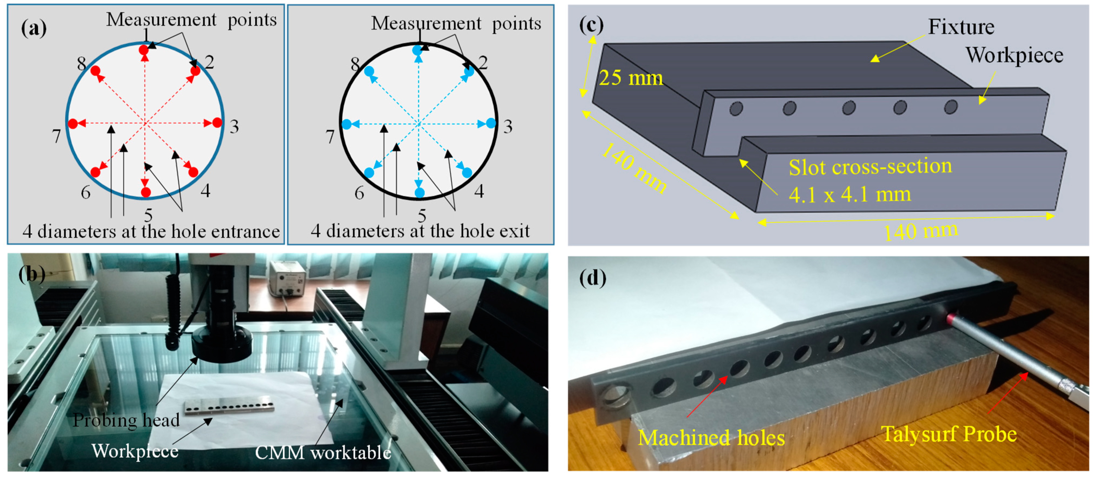
With reference to the measurements of each of the experimental runs, the machining time was carefully noted. The calculations of taper angle, radial overcut, and radial undercut primarily involve the measurements of different diameters (tool electrode, hole entry, and hole exit). All the diameters associated with each of the experimental runs were measured on coordinate measuring machine; CMM (CE-450DV, CHIEN WEI Precise Technology Co., LTD. Taiwan) with a 1 µm measurement accuracy. For each diameter, 8-points measurement was planned around the periphery of the circle as shown in Figure 3a. In this way four diameters were measured for a single circle and the average of four diameters was computed in the calculations of the taper angle, radial overcut, and radial undercut. Finally, the roughness of the inside surfaces of the machined hole was measured using Surtronic 128 roughness meter. The roughness tester was first calibrated using the standard specimen. Each measurement was recorded against an evaluation distance of 3 mm. Since, the workpiece consists of a 4 mm thick strip therefore prior to take the measurements of surface roughness a fixture was developed so that the results were accurate. A slot of the square cross-section ( 4.1   mm   × 4.1   mm ) was milled on an aluminum block and the worpiece was placed inside the slot. The schematic as well as the actual workpiece placed in the fixture is shown in Figure 3c,d. For each hole, repetitive measurements (three times) were executed and an average value was reported in the results. Surface roughness was measured in its three variants, i.e., Ra, Rt, and Rz. However, the roughness in terms Ra was only reported because of its common use in the industry.

3. Results and Discussion

EDM die sinking of tungsten carbide was attempted using ten different tool designs. The tool designs are mainly of three types named as conventional design (DC), relief angle design (DR), and relief angle with land design (DRL). The machining performance was evaluated in terms of machining time (MT), taper angle (ø), radial overcut (ROC), radial undercut (RUC), and surface roughness (SR) of the eroded holes. Experimental results revealed that each of the response characteristics significantly varied as the tool design is changed. For example, the machining time to complete the 4 mm through a hole in WC varied from 172 to 338 min, and the taper angle varied from 3.84 to 21°. The micrographs of the machined holes are shown in Figure 4. These micrographs consisted of enlarged images of the hole entrance and hole exit corresponding to each electrode design. The effect of each of the electrode designs and their variants on the set responses was analyzed through comparative bar-charts as discussed in the following section.

3.1. Effect of Electrode Design on Machining Time (MT)

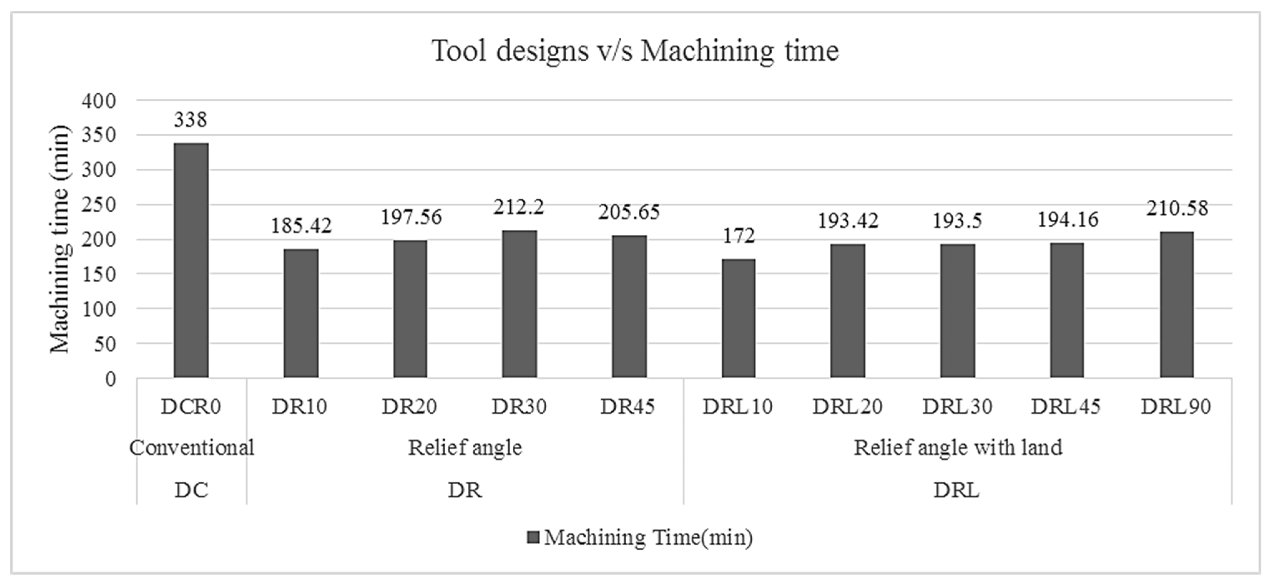
The effect of different electrodes on the machining time is graphically presented in Figure 5. The electrode with conventional design, i.e., cylindrical tool with no relief angle, completed the through a hole of 4 mm length in 338 min. As the design type was changed from the conventional (DCR0) to the relief angle (DR) and the relief with land (DRL), a substantial reduction in machining time was observed. The time to complete the hole by using the design type DR ranges from 185 to 205 min. Since, in the design type DR the relief angles were further varied, therefore as the degree of relief was increased to a certain extent (30°) the machining time was also increased. For example, the time taken by the 10 degree relief (DR10) was 185.42 min and the time consumed by 30 degree relief was found to be 212.2 min. However, by a further increase in relief angle (45°) the time was slightly reduced (205.65 min). It can be noticed that the pattern of machining time was somehow irregular as the relief angle was changed, but the machining time was substantially smaller than the time taken by conventional design. The fluctuation in machining time was around 12 min when the relief angles were 20, 30, and 45°. This fluctuation became more compact (less than 1 min) in the case of DRL type designs when relief angles were 20, 30, and 45°. The reason behind this fluctuation could be the change in current characteristics due to the presence of relief angles that need further research. Since EDM is a complex phenomenon and the prediction of discharge current and other parametric behaviors is difficult [23], therefore due to the complex nature of the process slight variations in the machining results can be expected. Thus the involvement of multiple aspects (current characteristics, discharge phenomenon, relief angle, debris flushing, etc.) could be another possibility behind a certain amount of variations among the machining results under relief angled electrodes. Within the subdesigns of DR the design with 10 degree relief offered the shortest machining time of 185 min. The third design type, i.e., relief with land (DRL) followed a similar increasing trend. Since in this design type the thickness of the land was kept constant and the relief angles were varied, therefore with the increase in relief angle the machining time also increased. Among the subdesigns of DRL, the minimum time was also observed in the case of 10 degree relief (DRL10) amounting to be 172 min. However, the time taken by 20, 30, and 45 degree reliefs were somewhat closer to each other. As the relief degree was further increased to a level of 90° the machining time tended to rise. Comparing all the nine designs of relief angled tools with the conventional cylindrical design the shortest time (172 min) was resulted by the tool having a 10 degree relief angle with a land thickness of 1 mm (DRL10). Considering the machining time corresponding to the conventional design as a reference, a 49% reduction in machining time could be achieved using the modified tool design (DRL10). Such a huge amount of time reduction might be recognized as a massive contribution in the field of EDM. Reduction in machining time eventually improved the material removal rate. Since, EDM is a very slow machining process and many decisions in machining industry declined due to the slow nature of this process, the use of relief angled tool design could boost up the machining rate of EDM. In this way, the productivity of EDM could be substantially improved.
The phenomenon behind this sound reduction in machining time is believed to be the sparking behavior in different tool designs. Since, the material removal during EDM is based on the successive sparks produced in front of the exposed surfaces of the electrodes. At the beginning of the machining feature (hole), the spark generation was initiated at the tool’s footing face and the material erosion was caused from the top surface of the substrate. In the case of conventional design type (cylindrical electrode; DCR0), as the machined feature progressed and a certain depth was achieved, the tool progressively tended to penetrate longitudinally inside the machined depth. At this stage, the surface area available to cause the sparking was greater. In addition to the footing face of the tool, the side surface around the tool periphery also produced electric sparks with the side walls of the machined feature. The phenomenon may be termed as the side sparking or the peripheral sparking. The surface area at the bottom of the tool remained constant throughout the machined feature. However, as the machining depth was further achieved the surface area of the tool around the periphery further increased because of the tool’s uniform cross-section. Resultantly, the amount of side sparking was enhanced as depicted in Figure 6a. The surface area available for the cumulative sparking (bottom sparking as well as side sparking) continuously went on increasing because of the uniform tool cross-section throughout the tool length. This endless increase in the surface area continued as long as the hole was formed. If the input spark energy remained constant and the surface area for electric discharges was increased, then the constant amount of energy needs to be distributed over the larger area (bottom surface plus the inner walls of the hole). In this way, the energy density per unit area reduced and consequently the machining rate slowed down. On the other end, the provision of the relief angle in the tool (DR) built the tapered walls of the tool instead of straight vertical walls. As a result, the gap between the hole’s inner walls and the tool’s side walls increased. The gap due to the relief angle was so enlarged that the voltage difference between the two walls became high and consequently it did not allow the spark to be initiated. In this way, the surface area available for sparking was the only tool’s bottom faced-area and the chances of side or peripheral sparking were minimized as could be envisioned from the schematic shown in Figure 6b. Since, during EDM the erosion of tool also took place along with the workpiece, therefore the possible drawback of this design (DR) could be the reduction in tool diameter at the bottom side due to the longitudinal wear of the tool.
Thus, another design type named as relief angle with land (DRL) was introduced in which the relief angle was provided at a height of 1 mm starting from the bottom end of the tool. The tool diameter remained the same within a 1 mm height and then reduced because of the relief angle. At the beginning of the machining, the sparking phenomenon during this design of the electrode was similar to the previous two designs. The sparking behavior changed as the machining depth progressed. Up to the machining depth of 1 mm, starting from the top most layer of the work surface, the surface area for sparking also increased (bottom surface and peripheral surface). This increase in collective surface area (bottom and peripheral) acquired a maximum value when the machining depth of 1 mm was achieved. As the depth further propagated the surface area for sparking remained constant since the sidewalls of the tool were straight in a 1 mm distance and after that the sides were tapered due to the provision of the relief angle. Thus, the gap between the inner walls of the eroded hole and the tool’s sidewalls (of 1 mm length) was short as compared to the gap between the inner walls of the hole and tapered sidewalls of the tool. In this way the sparking only occurred at the bottom and 1 mm sidewalls of the tool. In this case the phenomenon was termed as the moderate side sparking. This design type (DRL) might overcome the above stated drawback of the previous design (DR). Moreover, upon the tool wear of DRL along its length, the cross section of the tool at the bottom side remained uniform due to the land of 1 mm thickness. As the input discharge energy was constant (as in case of present research) and the surface area also became constant after a depth of 1 mm therefore a steady rate of erosion was observed. Thus, it could be inferred that the provision of the relief angles in the tool designs allowed the side or peripheral sparking to be at a minimum or moderate level. It could also be noticed that the amount of side sparking continuously increased in the case of the conventional tool design whereas it remained constant when the relief angles were introduced in the tool design. Against a fixed level of input discharge energy, if the spark density was continuously reduced the erosion rate would be slowed down and if the spark density remained constant the steady rate of erosion could be maintained. That is why the machining time to complete the through hole by conventional tool design (DCR0) was significantly high as compared to the time taken by the relief angled tool designs (DR and DRL) to finish the same hole in the same material under the same machining conditions.

3.2. Effect of Electrode Design on Taper Angle (ø)

The effects of tool designs and various relief angles on the degree of taperness of the machined holes have been presented in Figure 7. By the use of conventional design (DCR0), in which the sides of the tool are straight and parallel to the axis of the hole, the taper angle of 3.94° was observed. The second design type (DR), in which relief angles were provided and the sidewalls of the tool were not parallel to the hole axis, the taper angle was found to be larger than the taper angle in the case of the conventional tool design (DCR0). Furthermore, as the relief angle in the tool increased the taperness in the sidewalls of the machined hole also increased as can be observed from the red callout mentioned in Figure 7.
As the erosion progressed, the tool wear was experienced at the bottom and consequently the tool length mainly reduced. The wear in tool length reduced the diameter of the tool at the bottom end because of the presence of relief angle. The exit diameter of the machined hole became smaller. Thus, the difference in hole diameters (at the entrance and exit) resulted in a taper angle. This difference in diameters became more and more as the relief angle was increased from 10 to 45°. Consequently, the taper angle in the sidewalls of the hole increased. Among the tools designed under the category of DR the tool having a relief angle of 10° produced the minimum taper angle (4.21°) in the machined hole. A similar pattern of the hole taper angle was noticed in the case of third design type (DCR) in which relief angles were given after the 1 mm land thickness. In this design type, the side walls of the tool, at a height of 1 mm from the tool bottom, were parallel to the hole axis whereas after 1 mm the sides became inclined due to the presence of the relief angle. The maximum surface area available for the sparking remained constant for all the design variants of DRL because of a 1 mm land thickness. The total surface area for sparking is the summation of the bottom surface area and surface area of circular land of 1 mm thickness ( π × 4 2 + 2 π × 4 × 1 = 75.4   mm 2 ). In this way, the total surface area was 75.4 mm2, which theoretically remained constant in the case of DRL tools. Therefore, ideally the hole taper angle should remain constant but in actual the taper angle increased as the relief angle increased. The cause of this increase could be the change in current characteristics occurred due to the relief angles. As in the case of a 90 degree relief angle, it is possible that the behavior of the discharge current became erratic and the resulted taper of the hole reached a maximum value of 21.11°. Since EDM is a complex phenomenon and the prediction of discharge current and other parametric behaviors is difficult [23], therefore further research is needed to understand the change in current performance when a relief angle of 90° is provided. Hence, land with a relief of 90° was the worst design in terms of the hole taper angle. The minimum taper angle under the category of DRL was found to be in case of 10 degree relief with 1 mm land (DRL10). As a whole, if we compared the taper angles of all the ten designs, the minimum taper angle of 3.84° was achieved using the tool DRL10 in which the relief of 10° was provided with 1 mm land. Thus, DRL10 was the most appropriate tool to have the machined hole with a minimum taper angle.

3.3. Effect of Electrode Design on Radial Overcut at Hole Entrance (ROC_en)

Another performance characteristic of EDM considered in this study was the radial overcut at the hole entrance. Overcut is the universal fact of EDM, which indicates that the dimension of the machined impression along the horizontal plane is larger than the dimension of the tool. For example, by creating a circular impression through circular tool the size of the machined imprints comes out to be larger than the tool diameter. Since the progression of the hole is the result of such imprints, therefore an overcut is observed at the hole entrance. The half of the difference in the diameters of the tool and the hole entrance is termed as the radial overcut as described in the materials and methods section by Equation (3). Comparing the overcuts produced by all the tool designs, it was observed that the tool having conventional cylindrical design (DC) imparted the largest radial overcut, i.e., 249 µm. It indicates that the actual diameter of the produced hole, at the entrance, was 249 µm larger than the diameter of the tool. The overcuts resulted by the remaining tools (modified through relief angles and relief with land) were significantly less than the overcut caused by the conventional design as can be observed in Figure 8. There was no precise pattern of radial overcuts with the increase in relief angles, however the overall range of overcuts values was substantially smaller than overcut in the case of the conventional tool. The range of the overcut caused by the relief angle design type (DR) was from 115.5 µm to 152.75 µm. On the other end, for the design type of the relief angle with constant land thickness (DRL) the overcut was within the range of 176.25–203 µm. This range was somehow larger than the range obtained by the design type of DR. Since, in the case of the conventional design, the interacting surface area of the tool with the inner walls of the hole was the largest following by the surface area in the case of design type DRL and DR. The larger was the interacting surface area, the greater was the overcut at the hole entrance. That is why the overcuts produced by the design type DC (conventional design), DRL (relief angle with land), and DR (relief angle) were 249 µm, 176.25–203 µm, and 115.5–152.75 µm, respectively.

3.4. Effect of Electrode Design on Radial Undercut at the Hole Entrance (RUC_ex)

On the other side, the hole diameter at the exit plane seemed to be smaller than the actual tool diameter. The result of this difference in diameters was termed as the radial undercut at the hole exit, which was calculated, for all the tool designs, using Equation (4). The experimental results of EDM in terms of radial overcut against each of the ten designs are plotted as shown in Figure 9.
The major cause of the undercut at the hole exit was the presence of taperness alongside the inner walls of the machined hole. That is why graphical trends in the case of undercut were matching to those trends noticed for hole taper angle. For example, in the case of relief angle design type (DR) as the size of the relief angle increased from 10 to 45°, the undercut at the exit of the hole continuously increased. Tool wear was the main reason behind this progressive escalation in the undercut. As the tool worn out from the bottom plane the length of the tool was reduced. At the reduced length the corresponding diameter of the electrode also reduced due to the presence of the relief angle. Thus, the diameter of the electrode available at the final cuts, to finish the hole, was comparatively smaller than the diameter available at the initial cuts. In this way, the undercut was produced. The higher the relief angle is, the smaller the diameter of the electrode available to finish the hole at the exit layers is. Therefore, the high amount of undercut was produced as can be observed in the case of DR45, which produced the largest undercut (661.255 µm) within the category of tools with a relief angle design (DR). The trend of the undercut caused by the design type DRL was again similar to the trend of DR. Just in the case of the 45 degree relief the undercut was reduced. However, this reduction was so small (less than 5 µm) that it could be ignored. For example the undercut with a 30 degree relief is 343 µm whereas with a 45 degree relief it was 338.75 µm. Thus it can be said that the results pattern of DRL designs was similar to the case of DR designs. The design having a relief angle of 10° with 1 mm land (DRL10) produced the minimum of 92 µm undercut within the category of DRL design. An extraordinary undercut was observed in the case of DRL90 where the relief angle of 90 was provided. The exit diameter of the hole was found to be highly undersized as compared to the designed diameter of 8 mm. The land of 1 mm was found to be totally eroded, which indicates that the behavior of the current flow was highly erratic, which affected the electrode wear in an entirely different pattern as compared to the wear observed in all the other tools. Upon a comparison among the performance of different electrodes, it can be noticed that the minimum size of undercut at the hole exit was found to be 26.50 µm when conventional cylindrical tool (DC) was employed during EDM of WC. All the remaining electrode designs produced the larger amounts of undercuts in comparison with the conventional design. Thus, the conventional cylindrical design (DC) was relatively more practical if the objective was to keep the machined hole with minimum undercut at the exit plane of the hole.

3.5. Effect of Electrode Design on Longitudinal Tool Wear (TLW)

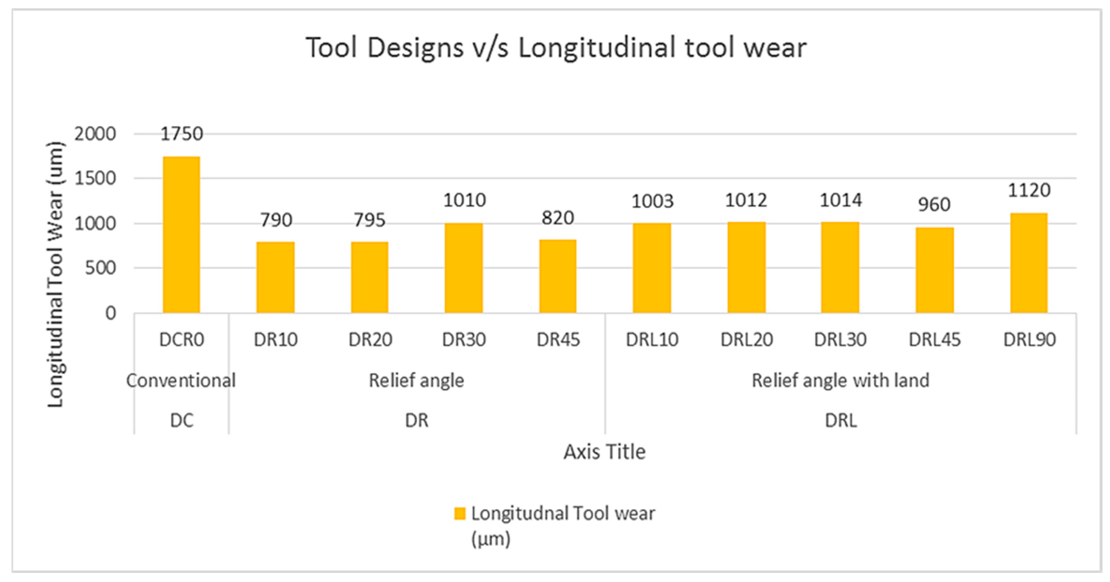
Length of each electrode was measured before and after machining. The difference in lengths is named as longitudinal tool wear. It was noticed that the maximum too wear was found in the conventional tool design (DC) as can be seen in Figure 10. On the other end the tool length reduction was found to be less in the case of all the modified tool designs compared with the conventional tool design. The main reason behind this reduction in tool wear was the machining time. Since the machining time for modified tool designs was smaller as compared to the conventional tool. Low machining time indicates that the time for the tool to be under machining conditions is small and hence the length of tool reduction becomes smaller. Within the category of relief angled tool designs (DR) as the relief angle increased the tool wear increased, except for 45 degree relief. A similar pattern was observed in the case of the tool design named as the relief angle with land (DRL). The reason behind this increasing trend again could be the change in discharge behavior of each electrode design. There is a possibility that by introducing the relief angle the discharge behavior changed from regular (as in case of conventional tool design) to irregular. Since, the shank of the tool was uniform throughout the length whereas the footing end of the modified tool was tapered. The change in the cross sectional area was involved. Due to this change in the cross section area the resistance to the discharge current varied. As a result, there was a possibility that the discharge characteristics were changed due to which the machining time as well as the tool wear was directly affected. A change in cross sectional area is different for different relief angles, thus the effect of relief angle over the current and discharge characteristics needs to be explored further. However, from the results it could be inferred that the minimum tool wear in longitudinal direction was found to be in the case of DR10 amounting to 790 µm.
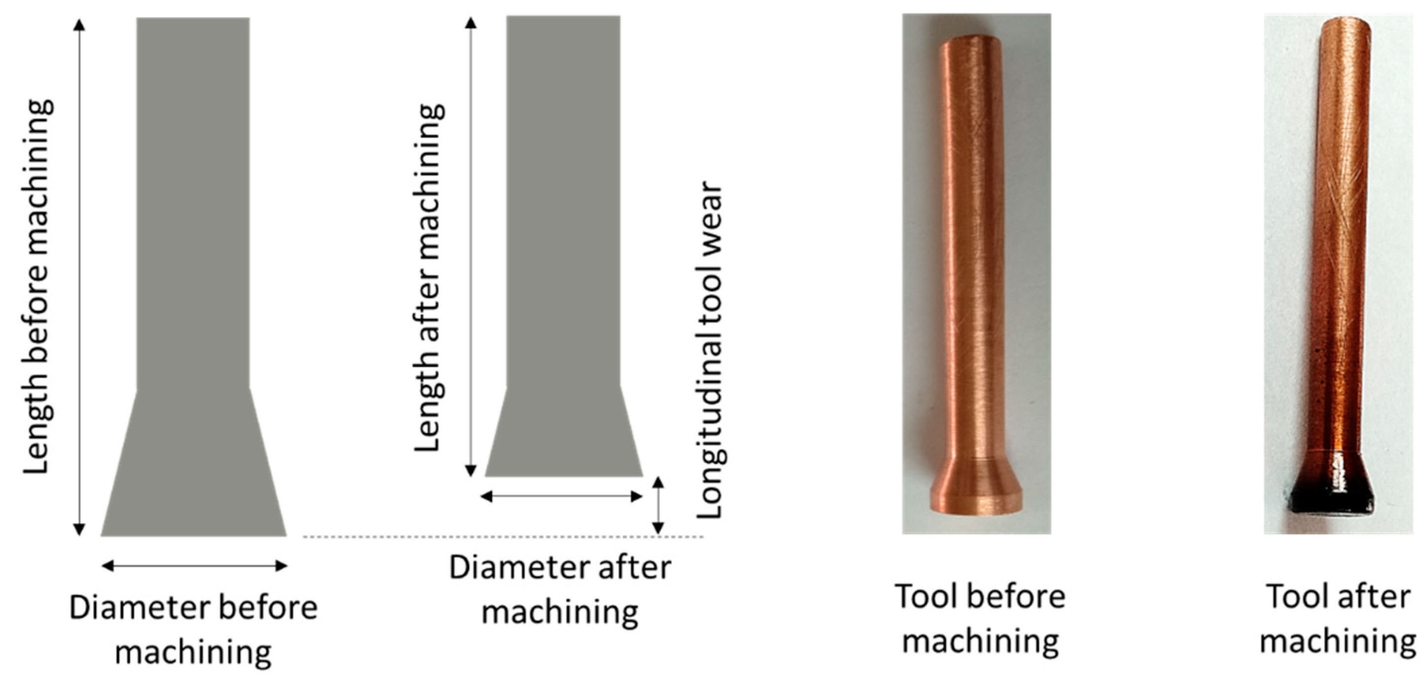
The effect of tool length reduction was directly over the radial undercut at the exit point of the machined hole. As the electrode length reduced due to the wear at the footing end, the diameter of the remaining tool reduced because of the presence of relief angle. The concept is further illustrated in Figure 11 wherein the length of tool before and after machining is presented schematically. Moreover, the actual tool before and after machining is shown as a sample. When the length reduced, the remaining diameter became smaller and as a result the diameter of the machined hole at the exit point was smaller than the diameter at the entrance. In this way, a radial undercut was observed. A change in tool length and diameter was greater with the increase in the relief angle, which is why the radial undercut also seemed to be larger in the case of large relief angles.

3.6. Effect of Electrode Design on Surface Roughness (SR)

The roughness of the inner walls of the machined holes has also been evaluated and the experimental results in a comparative format are presented in Figure 12. The roughness in its three characteristics (Ra, Rt, and Rz) were recorded, however, the reported values were in terms of Ra because of the widely used measure of roughness. Among the holes produced by all the ten electrode designs, the roughness corresponding to the design type DC was found to be the highest ones, i.e., 6.94 µm. all the other holes machined by the modified tool designs had a surface roughness less than the roughness of the hole machined by conventional design. The results in terms of surface roughness followed no systematic trend when the relief angles were changed. However, the hole produced with the tool having relief angle of 10° and land thickness of 1 mm (DRL10) had the minimum surface roughness (Ra = 4.42 µm). Although, there was close competition among the tool designs in terms of surface roughness but still the tool design DRL10 could be considered as the promising one as compared to the other designs especially in comparison with the conventional cylindrical tool (as can be witnessed from Figure 12).
Experimental results in a summarized form has been shown in Table 5, wherein all the six EDM responses (machining time; MT, taper angle; ø, radial overcut at the hole entrance; ROC_en, radial undercut at the hole exit; RUC_ex, longitudinal tool wear; LTW, and surface roughness; SR) were tabulated with minimum values achieved after experimentation. Among the ten tools employed during the EDM of WC in this study, each of the five response characteristics was evaluated and the top-three tools were ranked. As it can be witnessed from Table 5, the tool design in which a relief angle of 10° was provided with a land thickness of 1 mm, i.e., DRL10 acquired the first rank against three response attributes, i.e., machining time, taper angle, and surface roughness. The basis of this rank is the minimum response value resulted by the said tool. On the other end, the two response characteristics (radial overcut and radial undercut) were found to be minimum with the tool design other than the DRL10. However, in the case of these two responses the design DRL10 was in the second position. Thus, it could inferred that if the machinist had to opt for a single tool design to perform EDM of WC, then the design DRL10 could be considered as the preferred design since it can compete with the other designs in most of the response characteristics.

4. Conclusions

EDM of tungsten carbide; WC (famously considered as a difficult-to-machine material), was carried out using various tool designs to produce cylindrical holes of 4 mm depth with 8 mm diameter. The tool designs include the conventional cylindrical design (DC), relief angle design (DR) containing four relief angles (10, 20, 30, and 45°), and relief angle with a land design (DRL) consisting of five relief angles (10, 20, 30, 45, and 90°) with a land of 1 mm thickness. The performance was gauged through evaluating the machining time (MT), hole taper angle (ø), radial overcut at the hole entrance (ROC_en), radial undercut at the hole exit plane (RUC_ex), longitudinal tool wear (LTW), and the surface roughness (SR) of the inner walls of the machined holes. By considering machining outcomes, erosion phenomenon, and comparative analysis of tool designs’ performances, the following conclusions might be inferred:
  • Machining of WC was still difficult and time consuming through electric discharge machining. However, the difficulty level could be considerably reduced if design modifications in the tool design were introduced.
  • The machining results in terms of all the six performance characteristics (MT, ø, ROC_en, RUC_ex, LTW, and SR) were found to be relatively better when the newly designed tools (DR and DRL) were employed during EDM of WC. The leading phenomenon behind the improved machining characteristics was the result of the differences in the surface areas available for sparking (see the discussion associated with Figure 6)
  • The tool electrode with conventional cylindrical design (DC) took remarkably high machining time (338 min) to finish the through hole. A significant reduction in machining time could be realized by modified tool designs (DR and DRL). The design having a 10 degree relief angle with 1 mm land thickness (DRL10) was found to be the most preferred tool capable of machining the hole in 172 min. A 49% reduction in the machining time could be realized if DRL10 was employed during EDM of WC, thus, improving the productivity of the EDM process. In this way, the difficulty level in machining of WC could be soundly reduced.
  • Regarding the hole taper angle (ø), as the relief angle increased the corresponding taperness in holes’ sidewalls also increased. The tool having 10 degree relief with a land thickness of 1 mm (DRL10) produced the hole with minimum taper angle amounting to 3.84°.
  • There was a clear difference in the radial overcut at the hole entrance when the modified tool designs were employed. The tools with relief angle (DR) were found to be better than the conventional cylindrical tool in order to get the smaller overcut at the hole entrance. On the other, the undercut at the exit plane of the hole was smallest in the case of conventional tool design (DC).
  • Longitudinal tool wear (LTW) of modified tool designs was found to be substantially less than the tool wear in the case of the conventional tool design (DC). The minimum longitudinal tool wear was observed in the case of the 10 degree relief angle (DR10) with an amount of 790 µm.
  • There was close competition among the performance of all the electrode designs in the case of the roughness of the inner surfaces of the machined holes. However, the modified tool designs produced the surfaces with smaller roughness as compared to the roughness caused by the conventional tool design (DC). Moreover, the minimum roughness of Ra 4.42 µm resulted again by the tool DRL10, i.e., tool having a relief angle of 10° with a land thickness of 1 mm.
  • The tool design DRL10 could be considered as the most appropriate tool design capable of resulting significantly improved results for most of the five performance characteristics taken in this study.

Author Contributions

Conceptualization, N.A.M.; Data curation, M.R.; Formal analysis, N.A.M., M.R. and N.A.; Funding acquisition, N.A. and A.M.A.-A.; Investigation, M.R. and A.H.; Methodology, N.A. and M.Q.S.; Project administration, A.M.A.-A.; Resources, N.A.M. and A.H.; Software, M.Q.S.; Supervision, N.A.M.; Validation, M.Q.S. and A.M.A.-A.; Writing – original draft, N.A.M., M.R. and N.A.; Writing – review & editing, A.H. and A.M.A.-A. All authors have read and agreed the published version of this manuscript.

Funding

Raytheon Chair for Systems Engineering, King Saud University, Riyadh, Saudi Arabia.

Acknowledgments

The authors are grateful to the Raytheon Chair for Systems Engineering, King Saud University for funding.

Conflicts of Interest

The authors declare no conflict of interest.

References

  1. Lee, S.H.; Li, X. Study of the surface integrity of the machined workpiece in the EDM of tungsten carbide. J. Mater. Process. Technol. 2003, 139, 315–321. [Google Scholar] [CrossRef]
  2. Kung, K.-Y.; Horng, J.-T.; Chiang, K.-T. Material removal rate and electrode wear ratio study on the powder mixed electrical discharge machining of cobalt-bonded tungsten carbide. Int. J. Adv. Manuf. Technol. 2009, 40, 95–104. [Google Scholar] [CrossRef]
  3. Dewangan, S.; Chattopadhyaya, S.; Hloch, S. Critical Damage Analysis of WC-Co Tip of Conical Pick due to Coal Excavation in Mines. Available online: https://www.hindawi.com/journals/amse/2015/292046/ (accessed on 13 December 2019).
  4. Mahamat, A.T.Z.; Rani, A.M.A.; Husain, P. Machining of Cemented Tungsten Carbide using EDM. J. Appl. Sci. 2011, 11, 1784–1790. [Google Scholar] [CrossRef] [Green Version]
  5. Puertas, I.; Luis, C.J. Optimization of EDM conditions in the manufacturing process of B4C and WC-Co conductive ceramics. Int. J. Adv. Manuf. Technol. 2012, 59, 575–582. [Google Scholar] [CrossRef]
  6. Jahan, M.P.; Wong, Y.S.; Rahman, M. A comparative study on the performance of sinking and milling micro-EDM for nanofinishing of tungsten carbide. Int. J. Nanomanuf. 2010, 6, 190–206. [Google Scholar] [CrossRef]
  7. Jahan, M.P.; Wong, Y.S.; Rahman, M. A study on the fine-finish die-sinking micro-EDM of tungsten carbide using different electrode materials. J. Mater. Process. Technol. 2009, 209, 3956–3967. [Google Scholar] [CrossRef]
  8. Lee, S.H.; Li, X.P. Study of the effect of machining parameters on the machining characteristics in electrical discharge machining of tungsten carbide. J. Mater. Process. Technol. 2001, 115, 344–358. [Google Scholar] [CrossRef]
  9. Ahmed, N.; Ishfaq, K.; Rafaqat, M.; Pervaiz, S.; Anwar, S.; Salah, B. EDM of Ti-6Al-4V: Electrode and polarity selection for minimum tool wear rate and overcut. Mater. Manuf. Process. 2019, 34, 769–778. [Google Scholar] [CrossRef]
  10. Kumar, P.; Parkash, R. Experimental investigation and optimization of EDM process parameters for machining of aluminum boron carbide (Al–B4C) composite. Mach. Sci. Technol. 2016, 20, 330–348. [Google Scholar] [CrossRef]
  11. Singh, J.; Sharma, R.K. Multi-objective optimization of green powder-mixed electrical discharge machining of tungsten carbide alloy. Proc. Inst. Mech. Eng. Part C J. Mech. Eng. Sci. 2018, 232, 2774–2786. [Google Scholar] [CrossRef]
  12. Wang, C.; Qiang, Z. Comparison of Micro-EDM Characteristics of Inconel 706 between EDM Oil and an Al Powder-Mixed Dielectric. Available online: https://www.hindawi.com/journals/amse/2019/5625360/ (accessed on 13 December 2019).
  13. Ekmekci, B.; Yaşar, H.; Ekmekci, N. A Discharge Separation Model for Powder Mixed Electrical Discharge Machining. J. Manuf. Sci. Eng. 2016, 138, 081006. [Google Scholar] [CrossRef]
  14. Singh, J.; Sharma, R.K. Implementation of Taguchi method with hybrid decision making tools for prediction of surface characteristics for powder-mixed EDM of WC. Perspect. Sci. 2016, 8, 455–458. [Google Scholar] [CrossRef] [Green Version]
  15. Vishwakarma, U.K.; Dvivedi, A.; Kumar, P. Finite Element Modeling of Material Removal Rate in Powder Mixed Electrical Discharge Machining of Al-SiC Metal Matrix Composites. In Materials Processing Fundamentals; John Wiley & Sons, Ltd.: Hoboken, NJ, USA, 2013; pp. 151–158. ISBN 978-1-118-66219-9. [Google Scholar]
  16. Sharma, R.K.; Singh, J. Determination of multi-performance characteristics for powder mixed electric discharge machining of tungsten carbide alloy. Proc. Inst. Mech. Eng. Part B J. Eng. Manuf. 2016, 230, 303–312. [Google Scholar] [CrossRef]
  17. Jahan, M.P.; Saleh, T.; Rahman, M.; Wong, Y.S. Development, Modeling, and Experimental Investigation of Low Frequency Workpiece Vibration-Assisted Micro-EDM of Tungsten Carbide. J. Manuf. Sci. Eng. 2010, 132, 054503. [Google Scholar] [CrossRef]
  18. Abdullah, A.; Shabgard, M.R. Effect of ultrasonic vibration of tool on electrical discharge machining of cemented tungsten carbide (WC-Co). Int. J. Adv. Manuf. Technol. 2008, 38, 1137–1147. [Google Scholar] [CrossRef]
  19. Singh, P.; Yadava, V.; Narayan, A. Comparison of machining performance of hole-sinking micro-EDM without and with ultrasonic vibration on titanium alloy. Int. J. Precis. Technol. 2017, 7, 205–221. [Google Scholar] [CrossRef]
  20. Hsu, W.-H.; Chien, W.-T. Effect of Electrical Discharge Machining on Stress Concentration in Titanium Alloy Holes. Materials 2016, 9, 957. [Google Scholar] [CrossRef]
  21. Dave, H.K.; Mathai, V.J.; Mayanak, M.K.; Raval, H.K.; Desai, K.P. Study on effect of process parameters on overcut and tool wear rate during micro-electro-discharge slotting process. Int. J. Adv. Manuf. Technol. 2016, 85, 2049–2060. [Google Scholar] [CrossRef]
  22. Selvarajan, L.; Narayanan, C.S.; Jeyapaul, R. Optimization of Process Parameters to Improve Form and Orientation Tolerances in EDM of MoSi2-SiC Composites. Mater. Manuf. Process. 2015, 30, 954–960. [Google Scholar] [CrossRef]
  23. Chiang, H.N.; Wang, J.J.J. An analysis of overcut variation and coupling effects of dimensional variable in EDM process. Int. J. Adv. Manuf. Technol. 2011, 55, 935–943. [Google Scholar] [CrossRef]
  24. Moghanizadeh, A. Reducing side overcut in EDM process by changing electrical field between tool and work piece. Int. J. Adv. Manuf. Technol. 2017, 90, 1035–1042. [Google Scholar] [CrossRef]
  25. Ahmed, N.; Anwar, S.; Ishfaq, K.; Rafaqat, M.; Saleh, M.; Ahmad, S. The potentiality of sinking EDM for micro-impressions on Ti-6Al-4V: Keeping the geometrical errors (axial and radial) and other machining measures (tool erosion and work roughness) at minimum. Sci. Rep. 2019, 9, 17218. [Google Scholar] [CrossRef] [Green Version]
  26. Cui, J.; Chu, Z. Composite Motion Design Procedure for Vibration Assisted Small-Hole EDM Using One Voice Coil Motor. Available online: https://www.hindawi.com/journals/sv/2016/4179296/ (accessed on 13 December 2019).
  27. Cheema, M.S.; Dvivedi, A.; Sharma, A.K.; Biswas, S. Multicriteria Optimization of Rotary Tool Electric Discharge Machining on Metal Matrix Composite. In Materials Processing Fundamentals; John Wiley & Sons, Ltd.: Hoboken, NJ, USA, 2013; pp. 159–168. ISBN 978-1-118-66219-9. [Google Scholar]
  28. Goiogana, M.; Elkaseer, A. Self-Flushing in EDM Drilling of Ti6Al4V Using Rotating Shaped Electrodes. Materials 2019, 12, 989. [Google Scholar] [CrossRef] [PubMed] [Green Version]
  29. Chou, S.-H.; Wang, A.-C. Investigating and removing the re-sticky debris on tungsten carbide in electrical discharge machining. Int. J. Adv. Manuf. Technol. 2014, 71, 1151–1158. [Google Scholar] [CrossRef]
  30. Yadav, V.K.; Kumar, P.; Dvivedi, A. Performance enhancement of rotary tool near-dry EDM of HSS by supplying oxygen gas in the dielectric medium. Mater. Manuf. Process. 2019, 34, 1832–1846. [Google Scholar] [CrossRef]
  31. Zou, L.; Huang, Y.; Zhou, M.; Duan, L. Investigation on diamond tool wear in ultrasonic vibration-assisted turning die steels. Mater. Manuf. Process. 2017, 32, 1505–1511. [Google Scholar] [CrossRef]
  32. Groover, M.P. Fundamentals of Modern Manufacturing: Materials, Processes, and Systems, 6th ed.; Wiley: Hoboken, NJ, USA, 2016; ISBN 978-1-119-12880-9. [Google Scholar]
Figure 1. Electrode design details: (a) schematic of electrode designs and (b) actual electrodes of different designs.
Applsci 10 02432 g001
Figure 2. Schematic of hole dimensions: (a) taper angle and (b) radial overcut and undercut.
Applsci 10 02432 g002
Figure 3. Measurements of hole diameters and surface roughness: (a) schematic and actual measurement on coordinate measuring machine (CMM) and (b) schematic and actual measurement on Surtronic 128.
Applsci 10 02432 g003
Figure 4. EDM produced holes in WC using different designed tool electrodes: (a) hole produced though conventional tool design; DC, (b) holes produced through relief angle design tools; DR, and (c) holes produced through relief angle with land design tools; DRL.
Applsci 10 02432 g004
Figure 5. The effect of different design types on the machining time of EDM of WC.
Applsci 10 02432 g005
Figure 6. Sideway sparking during EDM: (a) conventional design; DC, (b) relief angle design; DR, and (c) relief angle with land design; DRL.
Applsci 10 02432 g006
Figure 7. The effect of different design types on the hole taper angle after the EDM of WC.
Applsci 10 02432 g007
Figure 8. The effect of different design types of the tool on the radial overcut at the hole entrance after the EDM of WC.
Applsci 10 02432 g008
Figure 9. The effect of different design types of the tool on the radial undercut at the hole exit after the EDM of WC.
Applsci 10 02432 g009
Figure 10. The effect of different design types of the tool on the longitudinal tool wear.
Applsci 10 02432 g010
Figure 11. Longitudinal tool wear during EDM with relief angled electrodes.
Applsci 10 02432 g011
Figure 12. The effect of different design types of the tool on the surface roughness of inner walls of the holes after the EDM of WC.
Applsci 10 02432 g012
Table 1. Elemental composition of tungsten carbide.
ElementPercentage
W88.3
Fe0.16
C4.9
Co5.9
Ni0.31
Table 2. Properties of tungsten carbide (mechanical, thermal, and electrical) [7,8,29].
PropertiesValuesUnits
Density15.5g/cm3
Hardness92.3HRA
Toughness50kg/mm2
Tensile strength179kg/mm2
Compressive strength410kg/mm2
Melting Point3140°C
Thermal conductivity0.502W/cm-°C
Thermal coefficient of expansion5.5 × 10−6K−1
Specific heat39.8J/molK
Electrical Resistivity17 × 10−6Ohm cm
Table 3. Electrodes and electric discharge machining (EDM) parameters (constants).
ParameterValuesUnits
ElectrodesToolCopper
WorkpieceTungsten carbide
EDM parametersDischarge current30 AA
Spark Voltage5 VV
Pulse on-time100µs
Pulse off-time50µs
Electrode PolarityWork+ve
Tool−ve
Servo sensitivity3
Spark-flushing time ratio1
DielectricKerosene oil
Flushing modeContinuous
Table 4. Tool electrode design details (design type, name, symbols, and dimensions).
Design TypeDesign NameDesign SymbolDesign Dimensions
AngleHeightDiameter
Relief Angle; Ɵ
(deg)
Land Height; LH
(mm)
Face Height; FH
(mm)
Shank Height; SH
(mm)
Total Height; H
(mm)
Face Diameter; FD
(mm)
Shank Diameter; SD
(mm)
DCConventionalDCR000050.005088
DRRelief angleDR101008.5041.505085
DR202004.1245.875085
DR303002.6047.405085
DR454501.5048.505085
DRLRelief angle with landDRL101018.5040.505085
DRL202014.1244.875085
DRL303012.6046.405085
DRL454511.5047.505085
DRL90901049.005085
Table 5. Summary of the experimental results to select the most appropriate tool design based on the decision criteria of minimum values of each of the six response characteristics (machining time; MT, taper angle; ø, radial overcut at the hole entrance; ROC_en, radial undercut at the hole exit; RUC_ex, longitudinal tool wear; LTW, and surface roughness; SR).
ResponsesMinimum ValueTool Ranking
Rank 1Rank 2Rank 3
Machining Time; MT
(min)
172.00DRL10DR10DRL20
Taper Angle; ø
(deg)
3.84DRL10DCR0DR10
Radial overcut;
ROC_en
(µm)
115.50DR20DR10DR45
Radial undercut;
RUC_ex
(µm)
26.50DCR0DRL10DR10
Longitudinal tool wear;
LTW
(µm)
790DR10DR20DR45
Surface Roughness;
SR
(µm)
4.42DRL10DR20DRL45
The most common tool designDRL10