1. Introduction
There has been considerable interest in small converters harvesting energy from various sources available in the environment, such as industrial machinery, civil structures, and even humans or animals. These systems are applicable in sensor networks or monitoring systems [
1,
2,
3,
4,
5,
6,
7,
8,
9] that require autonomy of power supply. The use of small generators of electric energy in such systems makes it possible to significantly increase an overall reliability, to eliminate wiring and reduce maintenance service activity over the whole system [
3,
10,
11,
12,
13,
14].
Most of the attention in the literature is focused on systems harvesting energy from mechanical vibrations. The minigenerators applied in these systems use various physical phenomena as the means of energy conversion. The most commonly implemented are piezoelectric, magnetostrictive, magnetoelectric, electrostatic and electromagnetic converters [
2,
15,
16]. This work concerns the latter system due to its reasonable power per unity of mass ratio and low manufacturing cost compared to the other types [
11,
13].
The coreless (iron-free) magnetic circuit is a common choice for application in electromagnetic vibration energy harvesting converters due to its simple design guidelines [
17]. It is well known that these systems suffer from a low value of induced electromotive force (emf), and thus generated power. Their very low volt-per-turn ratio often makes the impedance of the armature coils too high for the electronic boost of the induced voltage to any practical value. Here, we propose a routine that improves the performance of such a system by means of providing an optimal distribution of individual turns within the coil. This allows for a reduction of the impedance to an extent where the microgenerator connected to the electronic converter develops considerable output power.
In the design of electromagnetic vibration energy harvesters, the electromagnetic part is modelled using either numerical or analytical models [
8,
17,
18,
19]. In this work, the model segment of the routine involves determination of useful electromagnetic quantities by combining a 3D integral method, analytical formulas with a steady-state circuit simulation considering the electronic converter. For the purposes of the optimization process, it is not necessary to consider the whole system and its complicated kinematics resulting from the connection of the generator parts with elements of mechanical support [
20]. As a consequence, the motional effects are modelled as simply as possible, assuming that the displacement of the moving element of the converter is sinusoidal in time, which means that the system operates at a prescribed frequency and magnitude.
The optimization segment aims at the maximization of the power generated by the whole system. The considered optimization task is a mixed integer nonlinear programming (MINLP) problem [
21]. Due to the considerable evaluation time of the objective function, the kriging surrogate model [
22] is involved in the process. Three solution strategies are comparatively examined with respect to their cost and accuracy characteristics. The optimized system is successfully built and tested. The new contributions of this work are:
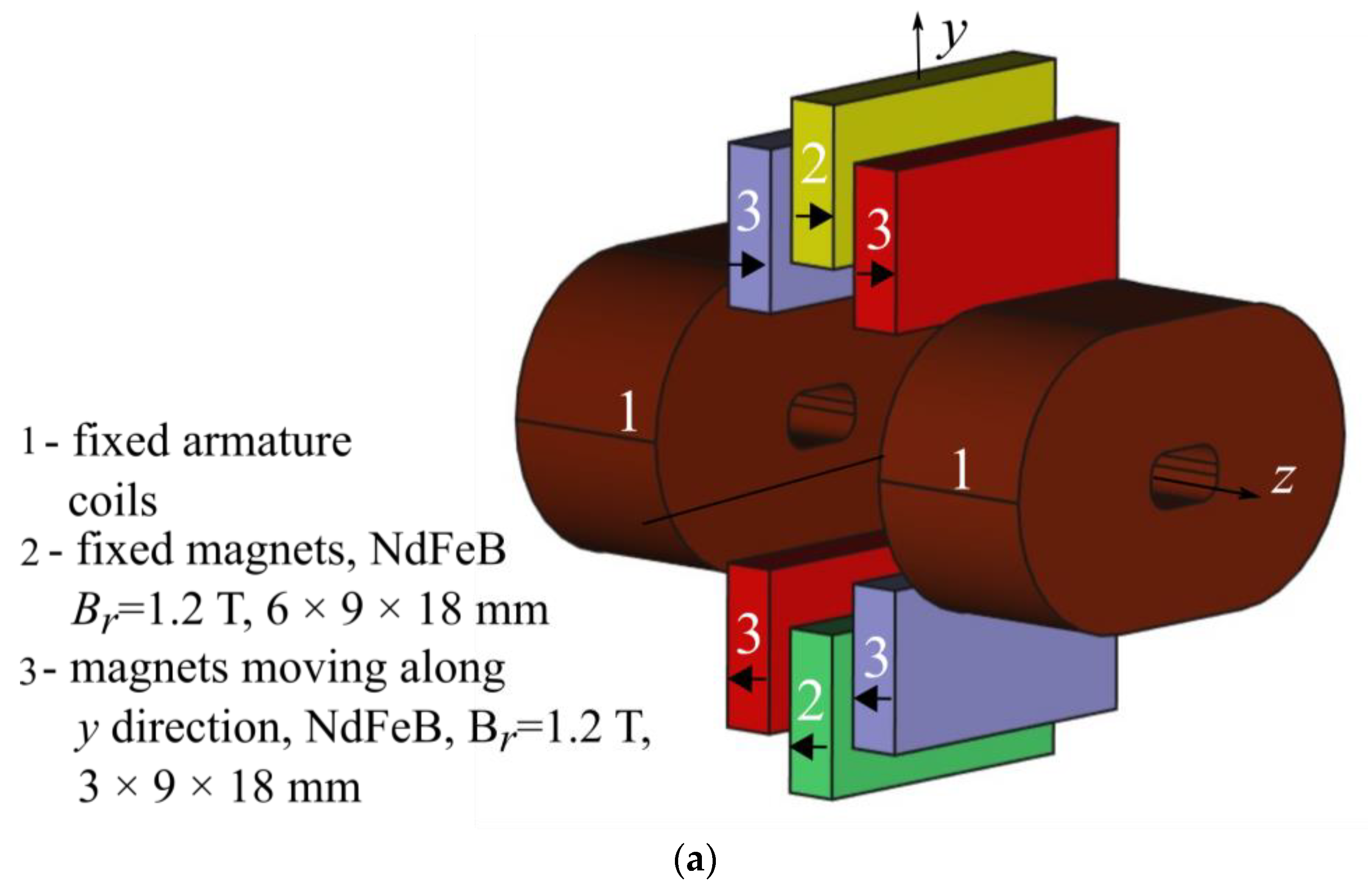
2. System and Its Mathematical Model
The CAD diagram of the considered microgenerator, variations of potential energy, and electronic converter are depicted in
Figure 1a–c.
The emf in armature coils 1 is induced as the result of the relative motion of magnets 3 along the
y axis direction. Magnets 2 are stationary with respect to the armature and are used to develop an auxiliary magnetic force that brings nonlinear mechanical resonance into the system. The converter belongs to a class of nonlinear electromagnetic vibration energy harvesters whose insightful analysis including kinematic and dynamic effects can be found in [
11] and [
20,
25].
Figure 1b shows variations of potential energy vs. relative displacement of permanent magnets (No. 3 in
Figure 1a). The senses of magnetization of the magnets in
Figure 1a determine the softening action of the magnetic force within the feasible range of displacement (between −5 mm and +5 mm), and two stable points around zero displacement (see
Figure 1b). With the variations of potential energy due to magnets (magnetic energy) and that due to auxiliary cantilever spring (spring energy) there is one static stable point at zero displacement. The frequency range where the system produces electric power is approximately equal to 10 Hz.
Due to lack of core element, the distribution of magnetic flux over the coil of the microgenerator shown in
Figure 1a is too nonuniform to assume that the induced emf can be calculated considering the coil as a block. For this reason, the optimization routine assumes that the emf is estimated for each turn individually. This apparently simple computation causes, however, a burden that needs further organization. Consider a single racetrack-shaped coil in
Figure 2.
As shown in the figure, the turns over a cross section of a uniformly wound coil are distributed one after another and then layer after layer in order to fill the assumed area w × h and are numbered repeatedly from left to right. Because the number of turns Nt has to be considered as a design variable, it should be noticed that it is not uniquely attributed to an electromagnetic quantity, such as the emf. It is only unique if it is attributed to turns ordered with respect to the value of the quantity. This attribution will be carried out as follows.
For the system in
Figure 1, the emf is induced only by the
z-th component of the magnetic flux density, whose distribution due to the
i-th magnet can be determined from:
where
is the vacuum permeability,
is the magnetic dipole density,
and
are the magnetization and surface-normal vector, respectively,
and
are the source and observation point, respectively, and
and
are the magnet surfaces parallel to the
xy plane. The useful quantity is, however, a derivative of turn-linked magnetic flux not the flux itself, as the former is in proportion to the turn-induced emf. For the
j-th turn, it can be conveniently calculated using Green’s theorem:
where
is the area enclosed by a single turn and
is the path along turn. It should be noted that the use of the final result of Equation (2) considerably reduces the time required for numerical integration and eliminates unwanted “noisy” variations of the quantity due to variations of turn dimensions that appear using surface integration over
and numerical differentiation with respect to
y. After evaluation of (2) for each turn of the cluster in
Figure 2, the results are ordered with respect to value by sorting and numbering from 1 to
Nt. This makes the turn ordinal number a unique design variable. At this instance, it should also be noted that:
If, for example, the call from the search algorithm includes a request for Nt = 100, the above described model returns the values of quantity (2) determined for the first 100 turns with the highest contribution to the emf.
Quantity (2) is determined without displacement of magnets 3 from the origin of the system of coordinates. It can be deduced that this position of the magnets corresponds with the maximum value of the turn-induced emf.
An important observation that makes the results of the optimization practical regards the fact that the ordered turns are not spread within the coil cross section, but they form an irregular cluster. This will be demonstrated further.
Determination of power
P generated by the system requires calculation of the coil impedance and the emf (sum of quantity (2) through
j) vs.
y for the given
Nt. The resistance and inductance are calculated using analytical formulas [
26,
27], taking into account the active and end-turn segments of the coil (
Figure 2)
where
,
are inner radius of
i-th turn and copper conductivity, respectively. The end-turn inductance of
i-th turn
, inductance of active segment of turn
, end-turn mutual inductance of
i-th and
j-th turns
and mutual inductance of active segments of
i-th and
j-th turns
are calculated from formulas
where
and
are complete elliptic integrals of the first and second kind and
Please note that the above formulas are valid even when L = 0, which means that the racetrack coil becomes a solenoid. The purpose of optimization is thus not only to optimally distribute turns within the coil cross-section but also decide whether a racetrack-like shape is better or worse than a solenoidal one.
The power
P is determined at a single frequency assuming a sinusoidal variation, a constant magnitude of displacement of magnets 3 and considering the power converter in
Figure 1c. The steady-state time-periodic circuit simulation using interpolated variation of
vs.
y is carried out for this purpose using program Plecs [
28]. The diagram of the computer model which implements all of the above described equations is shown in
Figure 3.
3. Optimization Strategies and Results
The considered optimization regards a 4D problem that is carried out in the following mixed integer design space
(see
Figure 1c and
Figure 2), with
Nt being an integer and
E(
D) the enumeration of wire diameters. The variable
Nt is considered continuous because its resolution is high (practical value is of order of a few hundreds) and rounding to the closest integer value has only a slight impact on power. The resolution of the second variable is low as only six different wire diameters are taken into account. Moreover, the sensitivity of power to variation in
D is considerable. It should also be noticed that this variable should be converted from enumeration to an integer.
The problem definition is
Due to the considerable time required for the evaluation of power using the computer model presented in
Section 2, the function
P(
X) is replaced by the surrogate model. The response
R of the computer model is evaluated at nodes of the Latin hypercube sampling-based design (LHS) grid
. Finally, the surrogate model
is created using the kriging approximation
.
The three following strategies are employed for the solution of problem (10):
Strategy I: Problem (10) is solved as its stands using nonlinear programming with an “integer” constraint equation in the form
. This can be considered as the most
ad hoc approach that can easily be implemented using many existing nonlinear search algorithms. Here we use the combination of global → local searches using genetic [
29] and the interior point algorithms [
30] one after another. The choice of a genetic algorithm as a global search method results from its ability to reliably localize the region with global extremum. The interior point algorithm is applied as a local search method due to its high precision and the ability to prevent violation of inequality constraints.
The strategy can be explained by the following pseudocode.
| Generate LHS grid and round X2 |
| Perform computer experiment |
| Create 4-D surrogate model |
| Optimize 4-D surrogate model with “integer” constraint |
The results obtained for different numbers of the LHS grid points are summarized in
Table 1.
Strategy II: Relaxation of integer variable. With only one integer variable considered, the solution strategy becomes a simplification of the branch-and-bound algorithm [
21] with far fewer sequences required to find the global extremum. For the solution of each 3D subproblem, we use once again the genetic and interior point algorithms. The following pseudocode explains the strategy.
| Relax integer variable |
| Generate 3-D LHS grid for continuous variables |
| for each value of integer variable |
| Create 3-D surrogate model |
| Optimize 3-D surrogate model and save solution |
| end |
| Find global extremum by ranking of extrema of relaxed subproblems |
The assumed resolution of the LHS grid is limited to 200 points, as shown in
Table 1, to provide enough accurate localization of the extremum even for the case with four variables accounted for. The results obtained from the current solution strategy are given in
Table 2.
Strategy III: Problem (10) is solved using a sequentially refined surrogate model. The strategy assumes starting from a low-resolution surrogate model and employs an adaptation of a design grid around the extremum to provide a reduction of execution time involving the creation of the surrogate model. The adaptation is performed repeatedly by adding extra LHS samples around the extremum unless the relative variation of the extremum is lower than the assumed error tolerance.
At each adaptation step the algorithm adds ten extra LHS points. The term “around extremum” means that these points are generated in the same design space, although with the boundary limited to 20 percent (in each direction) of the value of solution in previous step.
The search itself is carried out once again using the genetic and interior point algorithms one after another. The integer variable is constrained using the “integer” constraint equation, as in strategy 1. The pseudocode below explains the strategy:
| Set i = 0 |
| Generate coarse LHS grid Xi |
| Round integer variable |
| Assume |ΔX|max = 0.01 |
| Set |ΔX| = 1 |
| |
| while |ΔX| > |ΔX|max |
| Create 4-D surrogate model using Xi |
| Find Xi+1 by optimization of surrogate model |
| ΔX = |Xi+1 − Xi|/|Xi| |
| Add 10 LHS grid points around Xi+1 within ±20% of directional value |
| Round integer variable |
| i = i + 1 |
| end |
The results for different numbers of coarse LHS grid points are summarized in
Table 3.
The synthesis of all results leads to the following conclusions:
The most direct strategy (1) did not provide as high a value of power P as the other strategies even for a relatively fine LHS grid. The reason resides in the flatness of the objective function around the extremum.
Strategy 2 provides nearly the same values of power P as strategy 1, though exploration of the whole design space becomes extremely expensive.
Strategy 3 demonstrates the best performance with respect to the mentioned criteria. The highest value of power
P found by the strategy confirms the flatness of the objective function, which can be correctly explored using only very fine design grids. It can also be seen from
Table 3 that starting from a finer LHS grid can reduce the number of adaptation sequences. The differences between the values in the second and third row are related with the assumed error tolerance equal to 0.01 (see the pseudocode of the strategy III).
The maximum power is given in the second row of
Table 3. The corresponding optimum solution is
.
Figure 4 displays the distribution of wires over the cross section of a single coil of the twin-coil armature corresponding with the above solution. It should be noted that this result can easily be accomplished in the physical system, as shown in
Figure 4c.
Figure 5 displays the laboratory test-stand for validation of the obtained results. The comparison of powers measured for the systems with initially designed cylindrical coils with area w × h (dashed line in
Figure 4) filled uniformly with 2000 turns (
Figure 4a) and for that with the optimized racetrack coils (
Figure 4b). As shown in
Figure 5, the output power increased as much as by 300%. The slight (14 percent) differences between the results in
Table 3 and the maximum power measured for the optimized system are most likely due to complex (non-straight line) motional effects of magnets 3 on the induced emf in the physical harvester, which is a specific feature of the considered system that we identified and analyzed in [
20], and is also due to inaccuracy of manufacturing of physical coils where the turn distribution does not match exactly one presented in
Figure 4b. Though, the values of total coil resistance and inductance
Rc and
Lc measured using the laboratory multimeter agree to those calculated from formulas (3)–(9) within 2 and 6 percent, respectively (see
Table 4).
Figure 5c presents the measured characteristics of output power vs. frequency for the initial and optimal designs. The maximum power is reached at 35.5 Hz and is equal to 6.46 mW. Due to nonlinear magnetic force caused by interaction between moving magnets (magnets 3 in
Figure 1a) and stationary magnets (magnets 2 in
Figure 1a), the proposed energy harvester operates in the wide range of vibration frequency (around 10 Hz) providing output power sufficient to charge small Li-Ion battery in a power supply of a wireless sensor network. In comparison to reference systems of similar size operating at the same value of acceleration our converter has very similar range of operation frequency (7.8 Hz in [
31] and 10 Hz in [
32]), although it provides significantly higher output power (1.18 mW in [
31] and 2.5 mW in [
32]). The latter confirms the applicability and novelty of the proposed method for maximization of the output power of such systems.
4. Discussion
This work has shown a new possibility to significantly increase the output power for a class of electromagnetic vibration energy harvesting devices with its mathematical framework. The term “class” refers here to systems employing the coreless electromagnetic minigenerators that to this moment had to be designed with high number of turns detracting from their ability to deliver practical value of the output power. The overall idea of optimal placement of coil turn would also be applicable to other classes of converters, although the model for determination of circuit parameters outlined is
Section 2 may not be applicable directly.
It should be noted that the method was successful due to intentional choice of structure of the electronic converter which has an ability to boost the input voltage from values lower than 0.05 V, and which we selected testing earlier a few other structures. However, for such an excellent performance it requires a very small impedance of the coil connected to the input terminals. Without the boost converter the voltage generated by the optimized system would be even smaller than that of the reference systems mentioned in the preceding section.
It must be admitted that, generally, an optimization strategy based on the refined surrogate model, which we identified in this work as the best among the three considered strategies, is a known idea [
23]. However, it was used here in a different way and validated with respect to its potential to solve the mixed integer nonlinear optimization problem.
The successful optimization prompts the authors to modify the whole designing procedure of the converter so as to take account for more design criteria such as frequency bandwidth and overall mass. An application of the optimization strategy based on the refined surrogate model in solution of such a multi-objective optimization problem is a very challenging task.


