Article

Research on Semi-Active Vibration Control of Pipeline Based on Magneto-Rheological Damper

1
Beijing Key Laboratory of Advanced Manufacturing Technology, Beijing University of Technology, Beijing 100124, China
2
Beijing Aerospace Technology Institute, Beijing 100074, China
3
Apache Corporation, 17802 IH 10 West, Suite 300, San Antonio, TX 78257, USA
*
Author to whom correspondence should be addressed.
Appl. Sci. 2020, 10(7), 2541; https://doi.org/10.3390/app10072541
Submission received: 5 March 2020 / Revised: 2 April 2020 / Accepted: 3 April 2020 / Published: 7 April 2020
(This article belongs to the Section Acoustics and Vibrations)

Abstract

:
This paper proposes a scheme to control the low-frequency vibration of pipelines by using magneto-rheological (MR) vibration reduction technology. The state equation and the transfer function of the pipeline system are established, and its stability and the sinusoidal excitation response are analyzed. The prototype of MR damper is developed. The dynamic characteristics of MR damper are tested and the double-sigmoid model of MR damper is established. The two-state control, Proportion Integration Differentiation (PID) control and sliding-mode-variable-structure (SMVS) control methods of pipeline vibration using MR damper are analyzed comparatively, and the vibration control laws are deduced. The simulation analyses are carried out to predict the control effect of different pipeline vibration control algorithms. The verification tests through a semi-active measurement and control platform are carried out, and the feasibility and applicability of different pipeline vibration control strategies are analyzed. The test results show that the three kinds of pipeline vibration control methods based on MR damper can effectively control the pipeline vibration. Especially, SMVS control has the best vibration control effect, the pipeline amplitude drop and the acceleration drop can reach 22.31 dB and 16.34 dB respectively, while the amplitude attenuation rate and the acceleration attenuation rate can reach 92.34% and 84.77%, respectively.

1. Introduction

Pipeline system is an important carrier for the transmission of fluid and energy, which is widely used in power machinery, ship, aerospace, petrochemical industry, thermal system, sewage treatment system, water supply, drainage system and other fields [1,2]. During the flow process of fluid medium in pipeline, the pressure and velocity of fluid medium in pipeline will change due to the change of pipe diameter, pipe turning and other factors, as well as the opening, regulating and closing of valves in pipeline. The impact of pulsating fluid on the pipe wall will cause the vibration of the pipeline [3]. Moreover, the external vibration will also transmit the vibration of the matrix structure to the pipeline system through the pipeline connection fixture. Thus, vibration reduction of the pipeline system is crucial to the industrial production.
Over the past several decades, many research efforts have been made to study the dynamic behavior of pipeline, and several methods are proposed to settle structural vibration problems [4,5,6,7]. In a related field of vibration control, attaching a tuned mass damper (TMD) has become a widely accepted method for flexible and low-damped structures. Li et al. [8,9] proposed a pounding tuned mass damper (PTMD) which used the impact of a tuned mass with viscoelastic materials to mitigate the vibration of the flexible pipeline structures. Kiyar et al. [10] designed a pipe wall actuator, which was driven by an electromagnetic element for the active control of structure-borne and fluid-borne waves in a polyvinyl chloride (PVC): pipe filled with low-pressure water. Kartha [11] designed two types of fluid actuators (a side-branch actuator driven by an electromagnetic shaker and a Helmholtz resonator assembly with piezoelectric composite inside) to reduce the vibration power flow in a low-pressure fluid-filled pipe (7000 Pa). Yau et al. [12] presented an active control system using piezoelectric actuators based on regulator theory and robust control theory to restrain vibration of self-excited pipes.
Magneto-rheological (MR) damper based semi-active control systems could provide the reliability of a passive system and approach the effectiveness of an active control system without requiring heavy power supply. MR dampers have the advantages of strong damping force, broad temperature range, low energy consumption, fast response and simple structure [13,14]. Therefore, MR dampers have been widely applied in vibration and shock control, high-rise building anti vibration, vehicle suspension system, precision machining and crash worthiness systems [15,16]. It is feasible to control the vibration of pipeline by installing MR dampers in the fluid dynamic pipeline system, and using intelligent control strategy to control the vibration automatically according to the pipeline’s vibration response. The pipeline vibration control system based on MR damper is shown in Figure 1.
In this research, to reduce the low-frequency vibration, a semi-active control method for pipeline vibration based on MR damper is proposed. Firstly, a MR damper for pipeline vibration control is developed and the dynamic model of the MR damper is established. Then, the mechanism of pipeline vibration is expounded, the state equation of pipeline system is established, the transfer function of pipeline system is deduced, and the stability of pipeline system and sinusoidal excitation response are analyzed. Finally, the semi-active vibration control algorithms of pipeline, such as two-state, PID and sliding-mode-variable-structure (SMVS), are proposed, and the vibration control law of pipeline is deduced and simulated. The semi-active vibration measurement and control system of pipeline based on MR damper is built, and the vibration control performances of different pipeline vibration control algorithms are tested.

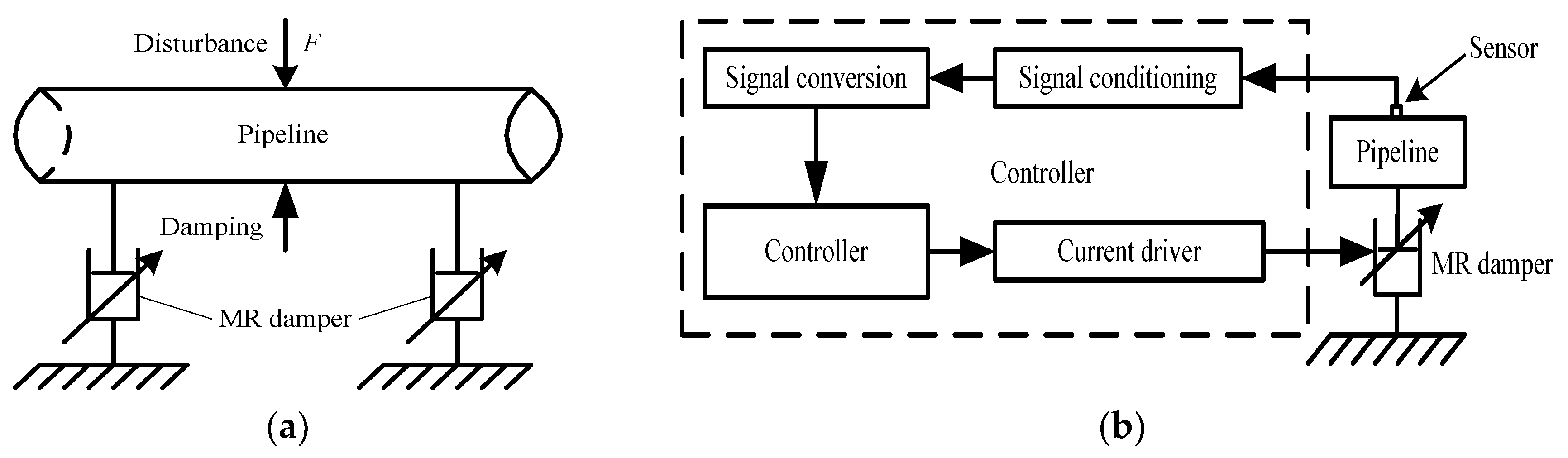
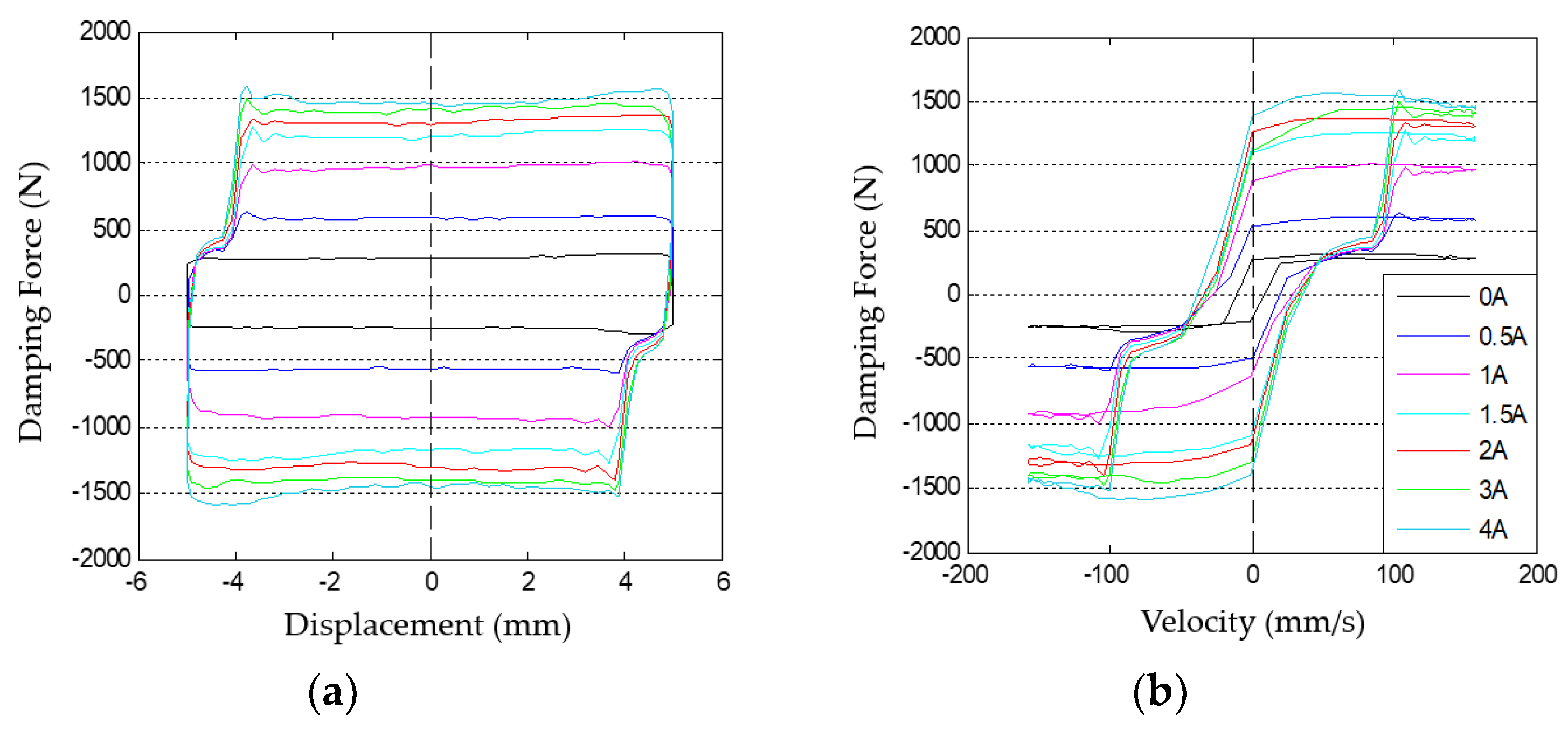
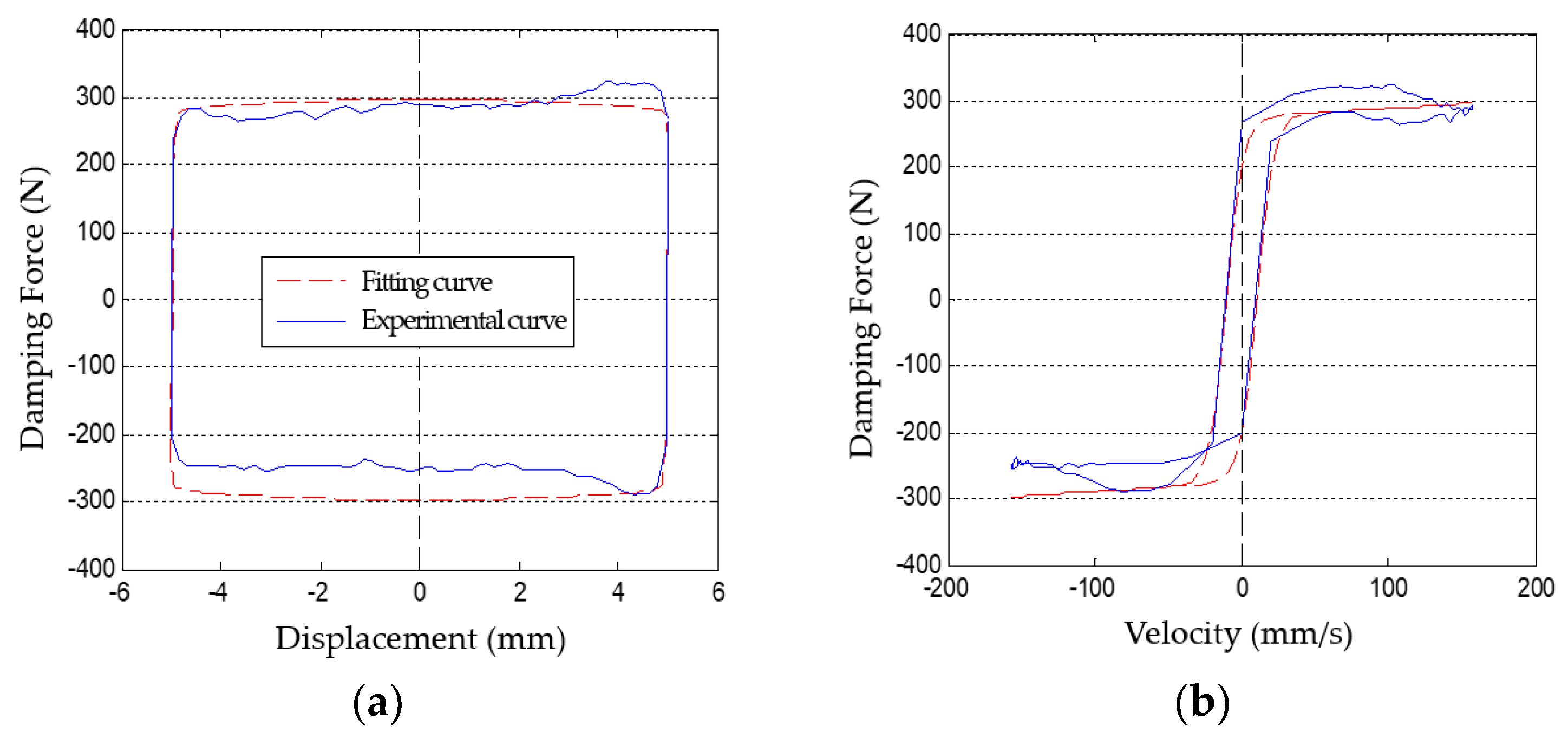
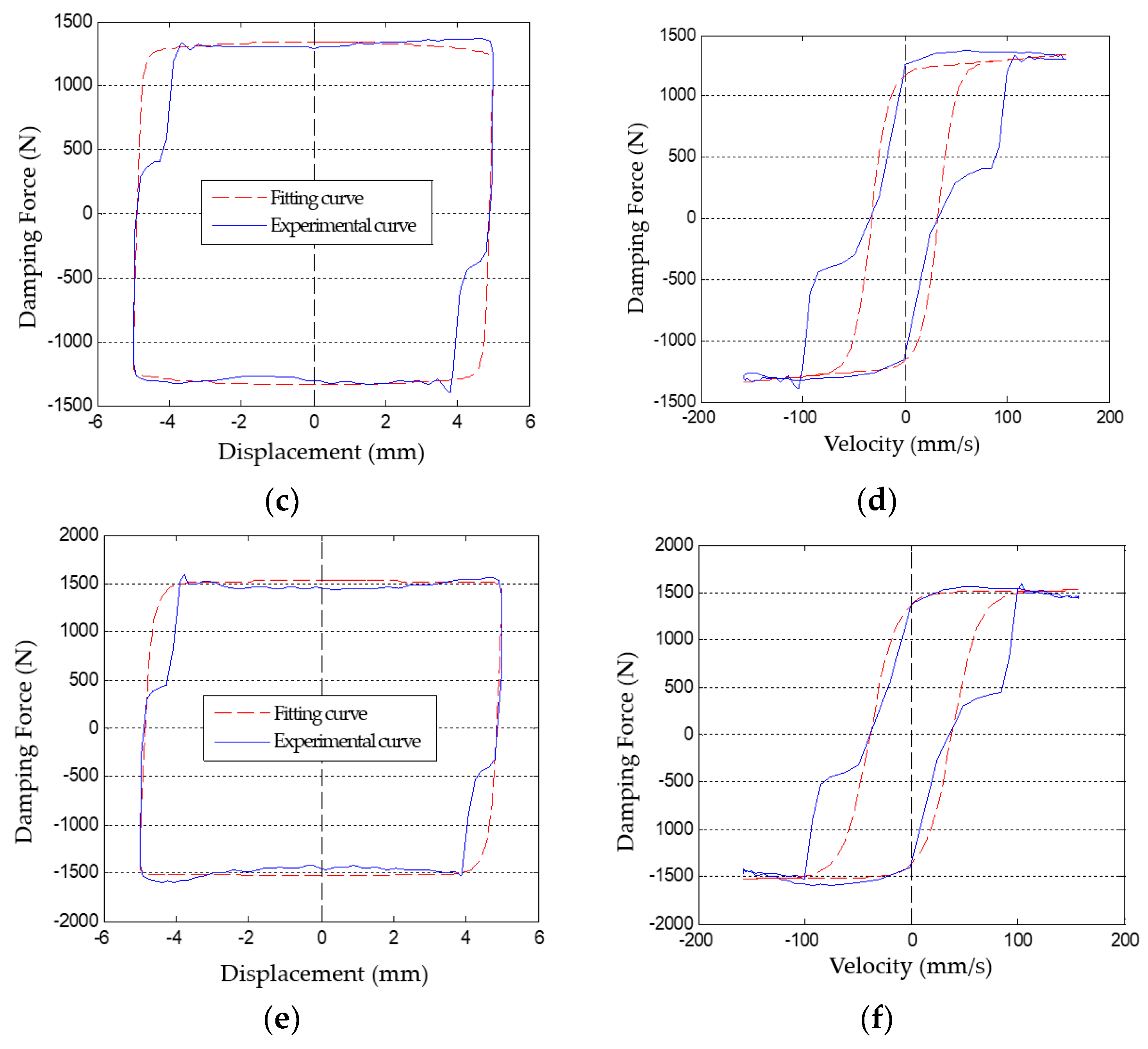
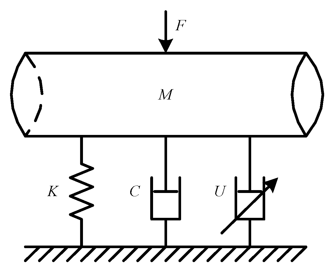
2. Model Description of MR Damper for Pipeline Vibration Control

According to the authors’ previous research [17,18], the double-ended shear-valve mode MR damper prototypes are fabricated in accordance with the characteristics of pipeline vibration. The testing system (as shown in Figure 2) includes the INSTRON-8801 test system, MR damper prototype and current controller. When the control current is 0–4 A, the dynamic characteristics of the MR damper are shown in Figure 3.
It can be seen from Figure 3 that, the damping force of the developed MR damper will enhance with the increasing current. As the current increases from 0 A to 1.5 A, the damping force is significantly proportional to the increment of the current. When the current exceeds 1.5 A, the damping force will slightly increase as the current increases. It is obvious that as the displacement and the velocity change, the damping force is slightly influenced under the same current, which implies that the damping force of the MR damper is not critically dependent on the displacement and the velocity.
In order to simulate the damping effect of MR damper under different vibration control algorithms, it is necessary to establish a dynamic mathematical model of MR damper and define the model parameters. Li et al. [19] proposed an double-sigmoid model, which took into account the effects of control current and excitation properties. The model had concise function form and high recognition accuracy, which could accurately and simply describe the output characteristics of MR dampers.
The damping force of MR damper based on the improved double-sigmoid model can be expressed as:
F = f d 1 e a ( x ˙ x 0 sgn ( x ) ) 1 + e a ( x ˙ x 0 sgn ( x ) ) + c d x ˙
where, f d is the adjustable coulomb damping force, c d is the viscous damping coefficient, x and x ˙ are the relative displacement and speed of MR damper piston and cylinder, x 0 is the displacement value of the MR damper force-velocity hysteresis curve when the damping force is zero, a is the velocity adjustment coefficient of coulomb damping force. Therefore, there are four undetermined parameters f d , c d , x 0 and a . Among them, the Coulomb damping force f d can be calculated, c d is the MRF zero field dynamic viscosity, x 0 can be obtained through the MR damper test data, and so only a needs to be identified in the model.
The parameters of the double-sigmoid model are identified by genetic algorithm, Figure 4a shows the basic flow chart of genetic algorithm. The MATLAB genetic algorithm toolbox is used as shown in Figure 4b. Using the experimental data of the MR damper, the undetermined parameters in the double-sigmoid model can be identified.
The function type selected through parameter identification is the minimum square value of the difference between simulation force and experimental force, to ensure that the final result of parameter identification can approximate the real value as possible. The fitness function can be expressed as:
f i t n e s s = 1 m i = 1 m ( F i f F i s F max F min )
where, F i f is the simulation value, F i s is the experimental value, m is the number of test sites, F max is the the maximum value of the initial population, F min is the minimum value of the initial population. The recognition results are shown in Figure 5.

3. Research on Semi-Active Pipeline Vibration Control System

3.1. State Equation of Pipeline System

The pipeline vibration control system is composed of pipeline, fluid medium in pipeline and MR damper, as shown in Figure 6. In the working process of pipeline system, fluid pulsation inside pipeline and vibration excitation outside pipeline act on the pipeline together, which will cause pipeline vibration. The pipeline vibration control system based on the MR damper can dynamically adjust the damping force of the MR damper according to the vibration characteristics of the pipeline, thereby controlling the vibration of the pipeline.
The motion equation of pipeline under environmental disturbance can be expressed as:
{ M X ¨ ( t ) + C X ˙ ( t ) + K X ( t ) = D s F ( t ) X ( t 0 ) = X 0 X ˙ ( t 0 ) = X ˙ 0
where, X is the pipeline displacement vector, M , C and K are the mass, damping and stiffness matrix of pipeline respectively, D s is the environmental disturbance location matrix, X ( t 0 ) and X ˙ ( t 0 ) are the initial displacement and velocity of pipeline.
In order to control the vibration response of pipeline system, MR dampers are installed in the pipeline system. The control force provided by MR damper is U ( t ) , and the corresponding position matrix of MR damper is B s . Then the motion equation of the pipeline under the control of the MR damper can be expressed as:
M X ¨ ( t ) + C X ˙ ( t ) + K X ( t ) = D s F ( t ) + B s U ( t )
Since the displacement X ( t ) and velocity X ˙ ( t ) of the pipeline system are independent variables, the system state vector can be expressed as:
Z ( t ) = [ X ( t ) X ˙ ( t ) ] 2 n × 1
In the state space, the controlled piping system described by Equation (4) can be expressed as:
{ Z ˙ ( t ) = A Z ( t ) + B U ( t ) + D F ( t ) Z ( t 0 ) = Z 0
In Equation (6):
A = [ 0 n I n M 1 K M 1 C ] 2 n × 2 n
B = [ 0 n × p M 1 B s ] 2 n × p
D = [ 0 n × r M 1 D s ] 2 n × r
where I n is the unit matrix.
The output state of pipeline system controlled by MR damper can be expressed as:
Y ( t ) = C 0 Z ( t ) + D 0 F ( t ) + B 0 U ( t )
where Y ( t ) is the output vector, C 0 is the output matrix, D 0 and B 0 are the direct transfer matrix.
Synthesizing (6) and (10), the controlled pipeline system under environmental disturbances can be described as:
{ Z ˙ ( t ) = A Z ( t ) + B U ( t ) + D F ( t )    Z ( t 0 ) = Z 0 Y ( t ) = C 0 Z ( t ) + B 0 U ( t ) + D 0 F ( t )

3.2. Frequency Response Function and Transfer Function of Pipeline System

For a single-degree-of-freedom piping system, the following equation can be obtained by Fourier transform at both ends of Equation (4):
ω 2 M X ( ω ) + j ω C X ( ω ) + K X ( ω ) = F ( ω )
The frequency response function of the pipeline system is as follows:
H ( ω ) = U ( ω ) F ( ω ) = 1 ω 2 M + j ω C + K
The polar form of Equation (13) can be expressed as:
{ | H ( ω ) | = 1 ( K ω 2 M ) 2 + ( ω C ) 2 ϕ = arctan ω C K ω 2 M
where | H ( ω ) | is the amplitude-frequency characteristics of frequency response function, ϕ is the phase-frequency characteristics of frequency response function.
The transfer function of the piping system is the ratio of the Laplace transform of the system response to the Laplace transform of the system excitation. The Laplace transforms of excitation F ( t ) and response U ( t ) are defined as:
F ( s ) = 0 + F ( t ) e s t d t
U ( s ) = 0 + U ( t ) e s t d t
where s = σ + j ω is the Laplace transform variable.
Under the zero initial condition, the following equation can be obtained by Laplace transformation on both sides of Equation (4).
( M s 2 + C s + K ) U ( s ) = F ( s )
Therefore, the transfer function of the piping system can be express as:
H ( s ) = U ( s ) F ( s ) = 1 M s 2 + C s + K

3.3. Comparative Analysis of Simulation of Different Vibration Control Algorithm

Based on the establishment of the pipeline system state equation, the pipeline system frequency response function and the transfer function, two-state control algorithm, SMVS control algorithm, PID control algorithm were employed to optimize the system characteristic parameters through simulation. The simulation models were established by using MATLAB.

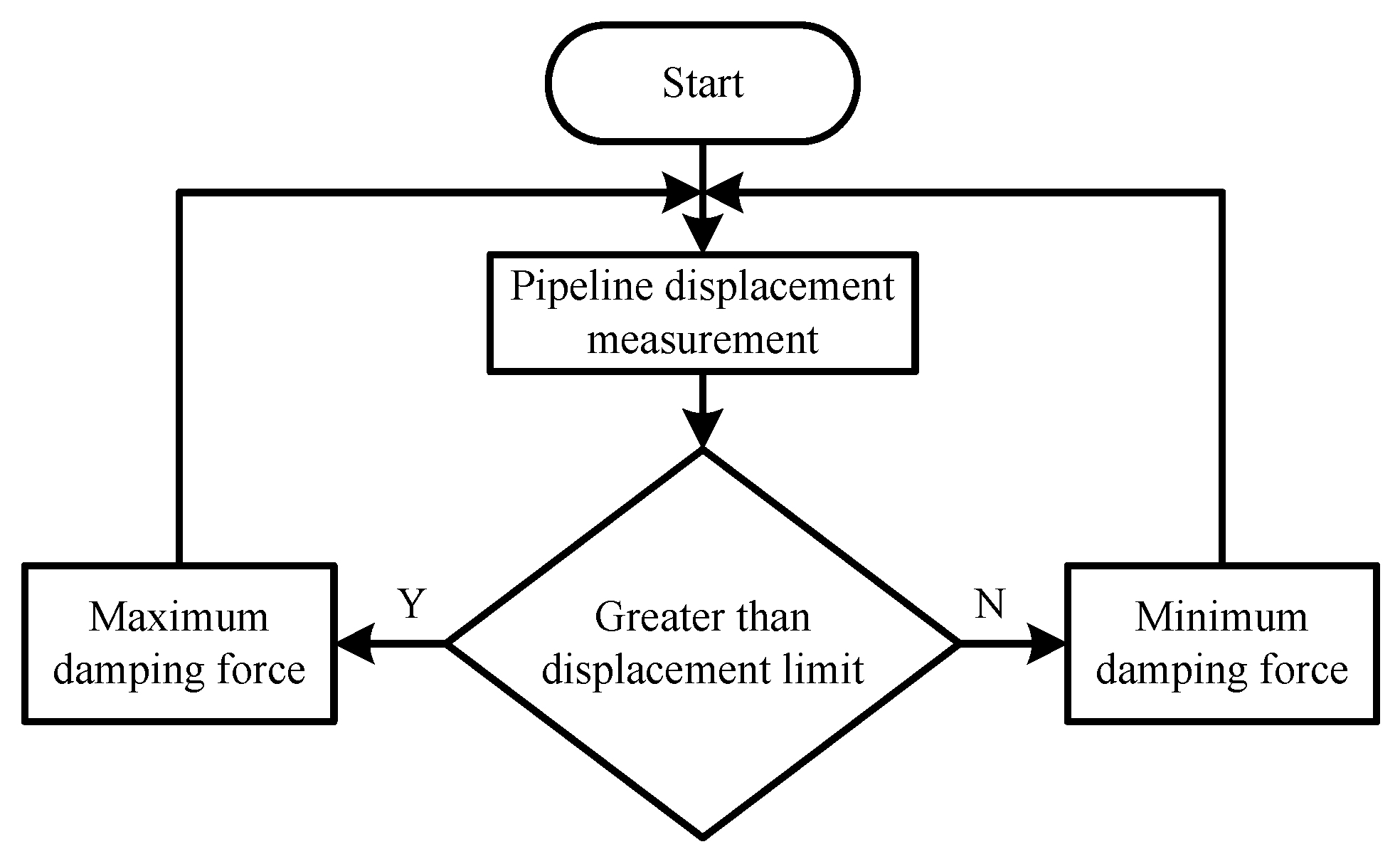
3.3.1. Two-State Vibration Control Simulation

In order to reduce the vibration response of pipeline as possible and make the pipeline always move to the equilibrium point after disturbance deviation, the following two-state vibration control method is established.
U = { F 2 x x ˙ 0 F 1 x x ˙ < 0
Equation (19) shows that when the pipeline is away from the equilibrium position under external disturbance, the MR damper is controlled to output a large control force; and when the pipeline is close to the equilibrium position, a small control force is output. However, the control algorithm takes the pipeline vibration balance point as the switching condition. When the pipeline vibration is in the initial, final or small amplitude, the two-state vibration control algorithm can easily lead to the overshoot of the control force and local amplification of the dynamic response of the pipeline. In order to solve the disadvantage of poor control effect of two-state vibration control near the pipeline equilibrium point, a dead zone is set up near the equilibrium point, that is, when the pipeline vibrates in the dead zone, only the minimum control force is applied to the pipeline. When the pipeline is far from the equilibrium position, and when the displacement of the pipeline exceeds a certain displacement limit, the MR damper is controlled to output a large control force. The two-state vibration control with dead zone is shown in Equation (20).
U = { F 2 x x ˙ 0   a n d   | x | [ x ] F 1 x x ˙ < 0   o r   | x | < [ x ]
where [x] is the minimum displacement limit.
The Simulink simulation model of the two-state pipeline vibration control system with dead zone based on MR damper is shown in Figure 7a. When the sinusoidal excitation amplitude is 2 mm and the frequency is 5 Hz, the vibration displacement response and control force simulation results of the pipeline under the two-state vibration control are shown in Figure 7b,c.
As shown in Figure 7, the two-state vibration control has better control effect on pipeline vibration, and the amplitude of the first peak of the transient response of the controlled pipeline system is higher than that of the uncontrolled one. When the vibration amplitude of the pipeline is equal to the minimum limit of the two-state vibration control, the system has a brief chattering. The transient process time of the controlled pipeline system is basically the same as that of the uncontrolled system. In comparisons with the uncontrolled system, the attenuation amplitude of the pipeline vibration adopting the steady-state two-state vibration control system is approximately 64.65%.

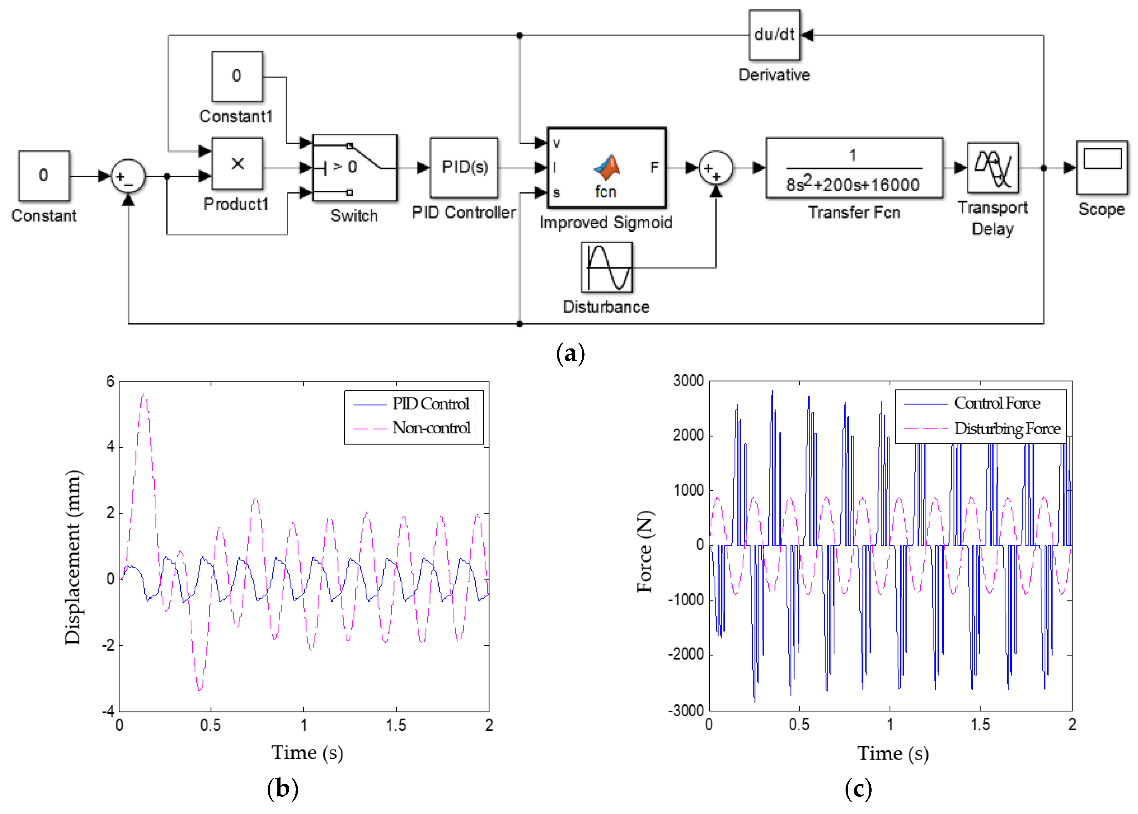
3.3.2. PID Vibration Control Simulation

The PID control has the advantages of simple control principle, low precision requirement for the controlled object model and overcoming the non-linearity of the controlled object. The basic principle of PID control is that the controller generates the control force u ( t ) to control the controlled object according to the control error e ( t ) , so that the output y ( t ) of the controlled object meets the requirements. When using the PID control, the control force u ( t ) can be expressed as:
u ( t ) = k p e ( t ) + k i e ( t ) d t + k d d e ( t ) d t
where k p , k i and k d are the proportional gain, the integral gain and the differential gain.
Since the MR damper can only output the control force opposite to the structural motion direction, when the vibration control reference control force is opposite to the structural motion direction, the PID control algorithm is used to control the output control force of the MR damper. When the reference control force is the same as the structural motion direction, the MR damper is controlled to output a minimum control force. The PID drive control law of the MR damper is as follows:
U = { u p i d u r x ˙ < 0 F min u r x ˙ 0
where U is the damping force of MR damper, u r is the reference control force, u p i d is the control force generated by PID control algorithm, x ˙ is the relative velocity of piston and cylinder.
The Simulink simulation model of the PID pipeline vibration control system based on MR damper is shown in Figure 8a. When the sinusoidal excitation amplitude is 2 mm and the frequency is 5 Hz, the vibration displacement response and control force simulation results of the pipeline under the PID vibration control are shown in Figure 8b,c, respectively.
As shown in Figure 8, the PID vibration control strategy can effectively control the pipeline vibration. In the transient phase of vibration response of pipeline system, the vibration of pipeline can be well controlled and no amplitude overshoot occur. The attenuation amplitude of the pipeline vibration adopting the PID vibration control in the steady state phase is 66.73%.

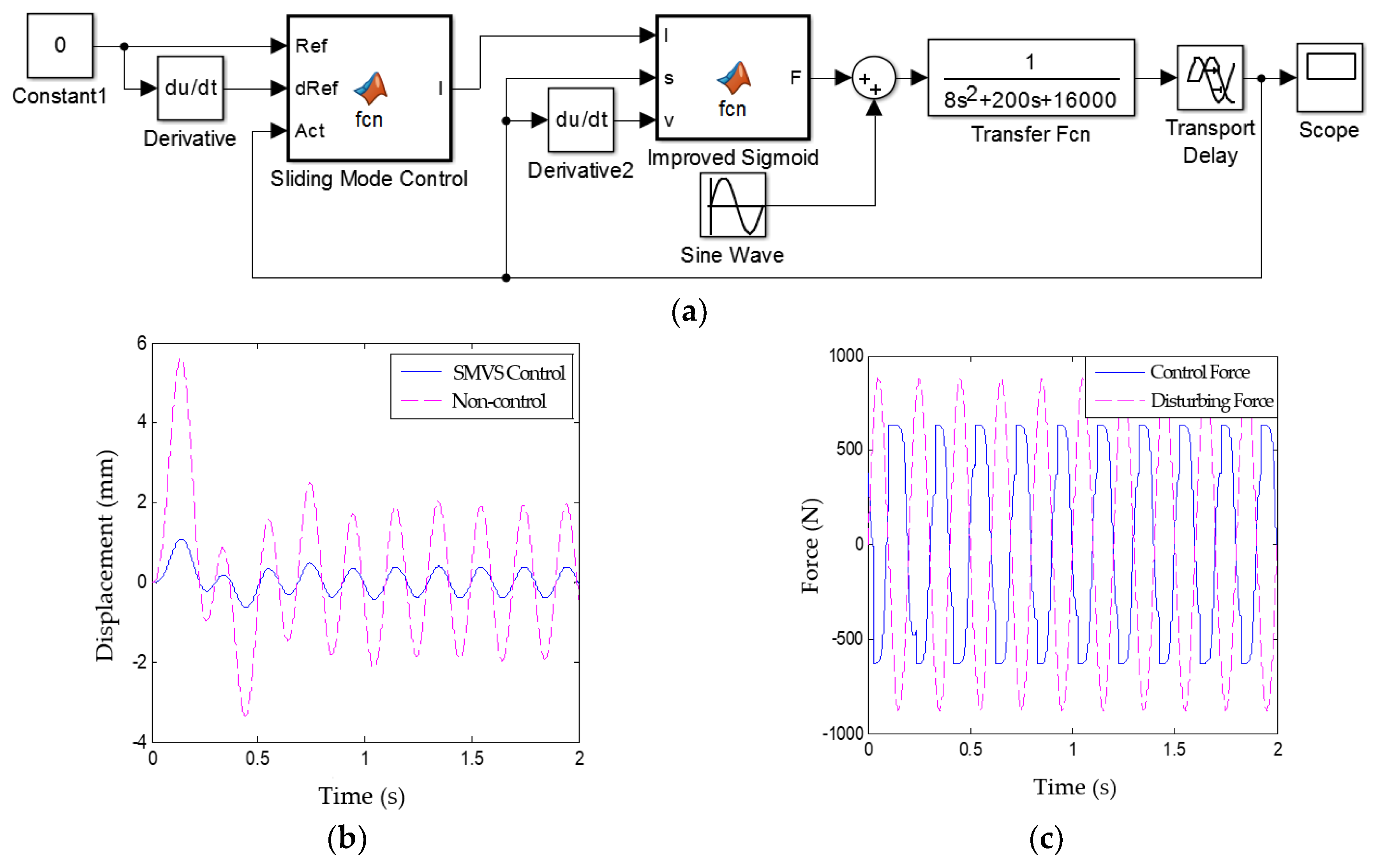
3.3.3. SMVS Vibration Control Simulation

SMVS control method makes the system state slide along the sliding surface by switching control variables, so that the system is invariant when disturbed by parameter perturbation or disturbance. The sliding mode can be designed independently of object parameters and disturbances, which makes the variable structure control having the advantages of fast response, insensitivity to parameter changes and disturbances, no need for online identification of the system, and simple physical implementation. It is suitable for linear and nonlinear systems, continuous and discrete systems, deterministic and uncertain systems, centralized parameters and distributed parameter systems, centralized control and distributed control systems.
Under the disturbance action, the output of the pipeline system is as shown in Equation (6). Since the pipeline system is an inertial system, D = 0 . The controlled pipeline system can be described by the following state equation:
{ Z ˙ ( t ) = A Z ( t ) + B U ( t ) Z ( t 0 ) = Z 0
The output goal of the pipeline vibration control system based on MR damper is to solve the control force U to keep the pipeline in equilibrium position under the external disturbance excitation.
lim t Z ( t ) 0 = 0
The pipeline vibration error function can be expressed as:
e ( t ) = Z ( t )
According to Equation (23), error and the rate of change of error can be expressed as:
e = Z = Z ˙ A + B U A
e ˙ = Z ˙ = A Z + B U
The switching function of pipeline system is defined as:
S = k e = k A ( Z ˙ + B U )
S ˙ = k e ˙ = k ( A Z + B U )
Using the exponential reaching law, the switching function of the system can be expressed as:
S ˙ = ε sgn ( S ) δ S    ε > 0 , δ > 0
By substituting Equation (28) and the Equation (29) into Equation (30), the following equation can be obtained:
U = ε A k δ ( A B B ) sgn ( S ) + Z ˙ A B B
The Simulink model of the SMVS pipeline vibration control system based on MR damper is shown in Figure 9a. When the sinusoidal excitation amplitude is 2 mm and the frequency is 5 Hz, the vibration displacement response and control force simulation results of the pipeline under the SMVS vibration control are shown in Figure 9b,c. The SMVS vibration control strategy can effectively control the pipeline vibration. The attenuation amplitude of the pipeline vibration of the SMVS vibration control in the steady state phase is 79.72%.
From the simulation results above, it can be seen that the SMVS vibration control algorithm has the highest attenuation rate of the pipeline vibration amplitude in the steady state phase, which is 79.72%. However, because the SMVS control is progressively stable, the vibration amplitude of the PID vibration control system in the transient state is smaller than that of the SMVS vibration control system. The control effect of two-state vibration control system on the pipeline vibration is general.

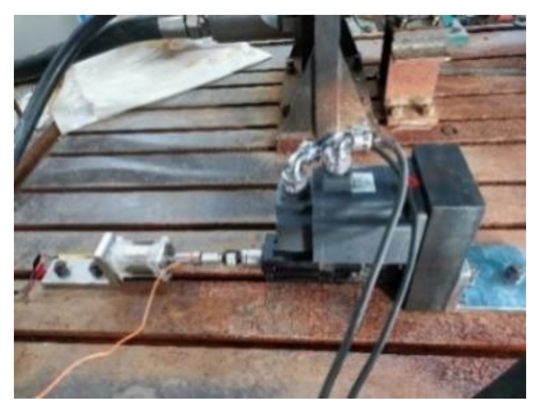
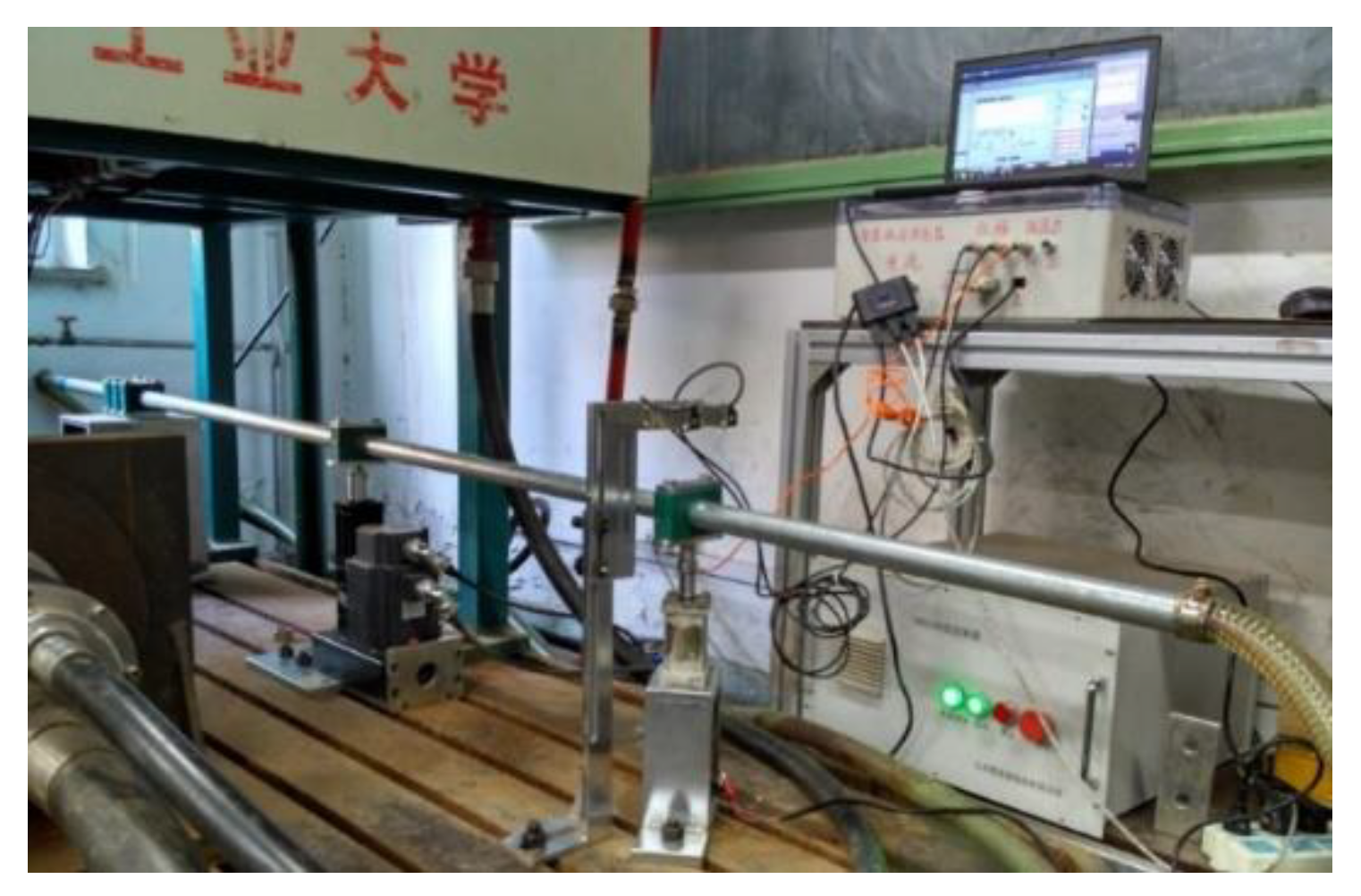
4. Experimental Study on Semi-Active Vibration Control

4.1. Pipeline Vibration Experiment Scheme

The experimental system is mainly composed of pipeline, MR damper and its embedded drive control system, vibration signal detection system, vibration excitation device, power system and computer. The schematic diagram of the fluid dynamic pipeline vibration measurement and control system based on MR damper is shown in Figure 10.
Here the servo electric cylinder is used to apply the excitation of different frequencies and amplitudes to the tested pipeline. The embedded vibration control system based on Digital Signal Processor (DSP) collects pipeline displacement signals and damper force signals from sensors. Then the optimal control force of pipeline vibration control is calculated according to the pipeline vibration control algorithm. Finally, the damping force of MR damper is controlled to reduce the vibration of pipeline. The pipeline vibration test system includes the acceleration sensor, INV3018A data acquisition instrument, vibration data acquisition and analysis software DASP to collect and analyze the pipeline vibration acceleration information. The laser displacement sensor, the tension pressure sensor, the NI6210 data collector and the Labview-based data acquisition software are selected to collect and record the pipeline vibration displacement and the MR damper control force. The pipeline vibration test platform is shown in Figure 11.
The vibration level difference or the vibration attenuation rate is usually used as an indicator for evaluating the vibration control effect [20]. The vibration level difference of pipeline is 10 times of the logarithm of the square of the effective value of vibration response when the pipeline is uncontrolled and the square of the effective value of vibration response when the pipeline is controlled. Vibration response may be displacement, velocity or acceleration. Since the vibration speed of the pipeline cannot be directly measured, the displacement level difference and the acceleration level difference of the pipeline vibration can be expressed as:
L x = 20 lg x u r m s x c r m s
L a = 20 lg a u r m s a c r m s
where x u r m s and x c r m s are the effective values of the vibration displacement when the pipeline is uncontrolled and controlled, respectively. Following this, a u r m s and a c r m s are the effective values of the vibration acceleration when the pipeline is uncontrolled and controlled, respectively.
The vibration attenuation rate is the ratio of the difference between the effective values of the vibration response before and after the pipeline is controlled and the effective value of the vibration response when the pipeline is not controlled. The displacement attenuation rate and the acceleration attenuation rate can be expressed as:
J x = x u r m s x c r m s x u r m s × 100 %
J a = a u r m s a c r m s a u r m s × 100 %
The vibration energy dissipation rate of the pipeline vibration control system can be expressed as:
J e = a u r m s x u r m s a c r m s x c r m s a u r m s x u r m s × 100 %

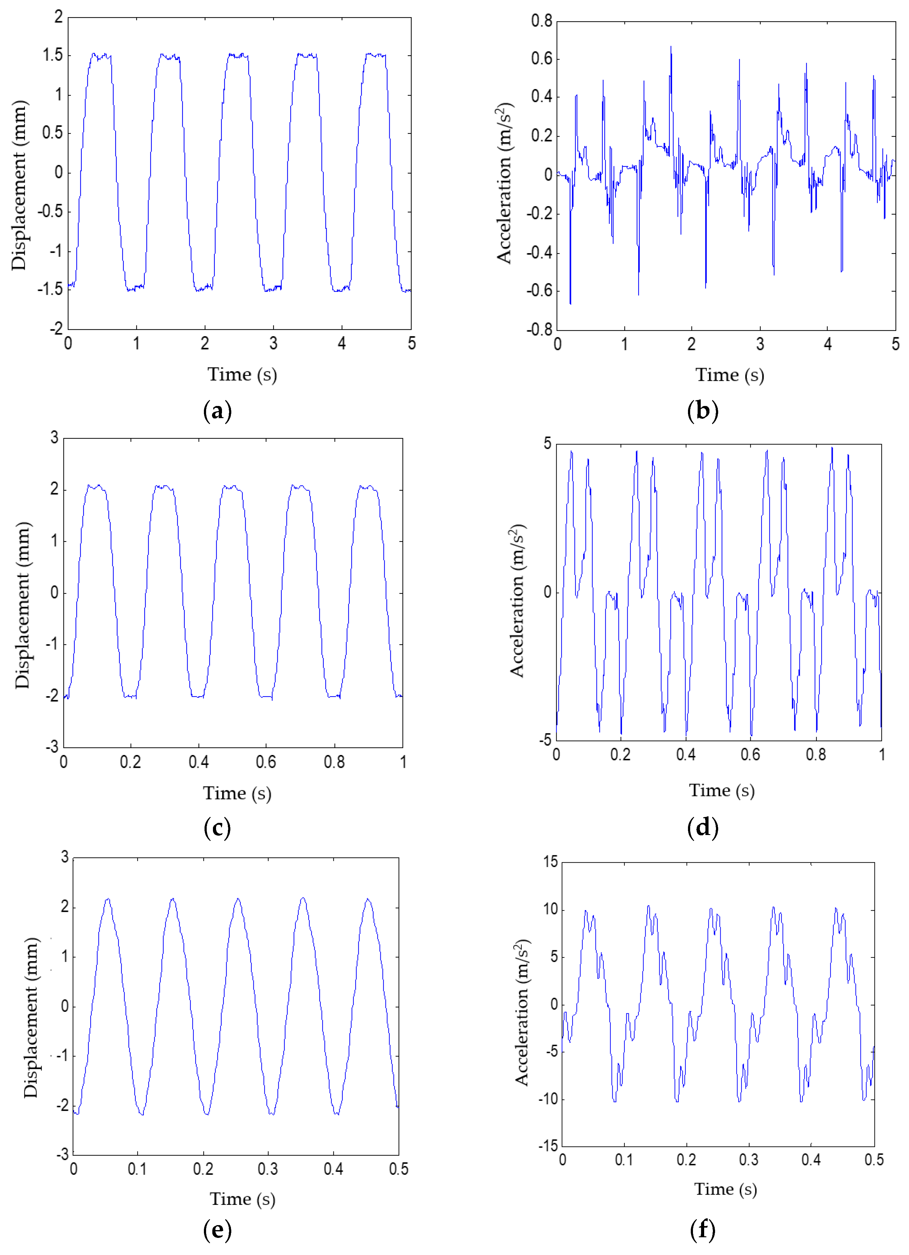
4.2. Pipeline Vibration Response Without Control

The uncontrolled vibration response of the pipeline will be used as a reference for measuring the effect of pipeline vibration control. For a signal acquisition system, the higher the sampling frequency of the signal, the closer the information collected by the acquisition system is to the real signal. However, too high sampling frequency will generate a large amount of data and introduce high frequency noise, which is not conducive to the reconstruction and analysis of pipeline vibration signals. Therefore, the sampling rate of the signal acquisition system is 1 kHz and 5 kHz respectively. The displacement response and acceleration response of pipeline under sinusoidal excitation with amplitude of 2 mm and frequency of 1 Hz, 5 Hz and 10 Hz are shown in Figure 12.
As shown in Figure 12, the vibration displacement curve of the pipeline conforms to sinusoidal, and the amplitude of the vibration displacement of the pipeline increases with the increase of the vibration frequency. However, the acceleration signal is more severe when the vibration frequency is lower. The main reason is that the piezoelectric acceleration sensor has low signal-to-noise when the vibration frequency is low. The statistical results of the vibration response of the pipeline at different excitation frequencies are shown in Table 1. Table 1 shows that the peak values of vibration displacement and acceleration of pipeline under sinusoidal excitation are 2.3505 mm and 10.6674 m/s2. When the frequency of pipeline vibration is 7 Hz, the peak value and root mean square (RMS) of pipeline vibration displacement are the highest.

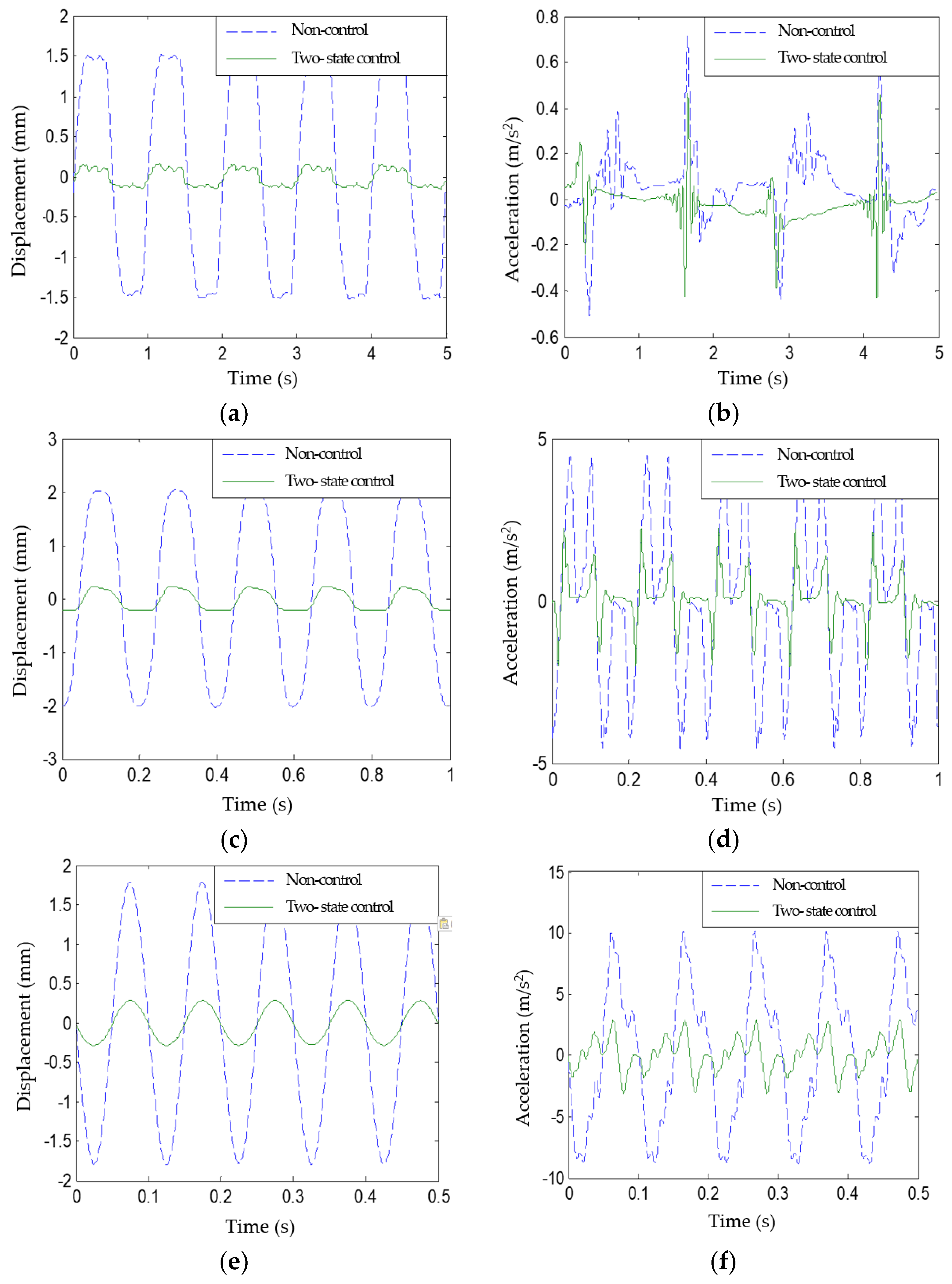
4.3. Two-State Vibration Control Experiment

Two-state control is the simplest control method, and it is also the most widely used semi-active control strategy for MR damper. The two-state control process is shown in Figure 13. The strategy of two-state control is to set the amplitude reference on both sides of the structural vibration equilibrium position. When the structural vibration amplitude is less than the set value, the control current is not applied to the MR damper, and the MR damper only passively outputs the foundation viscous damping force to attenuate the pipeline vibration. When the structural vibration amplitude is greater than the set reference value, a control current is applied to the MR damper, and the MR damper is controlled to output a damping force, which can control the structural vibration amplitude within a certain range. When the sinusoidal excitation frequencies are 1 Hz, 5 Hz, and 10 Hz, the vibration response test results of the pipeline under the two-state vibration control are shown in Figure 14.
When the vibration control of the pipeline is controlled by the two-state vibration control, the statistical results of the vibration response of the pipeline under different excitation frequencies are shown in Table 2.
As shown in Table 2, when the vibration of the pipeline is controlled by the two-state control, the displacement and acceleration of the pipeline are significantly reduced. As shown in Table 2, the displacement drop of the pipeline vibration at different excitation frequencies ranges from 14.5904 to 21.9312 dB, the acceleration drop range is from 4.4697 to 14.5449 dB, the displacement attenuation range is from 81.36% to 91.99%, and the acceleration attenuation range is from 40.23% to 81.26%, and the vibration isolation rate ranges from 88.86% to 98.28%.

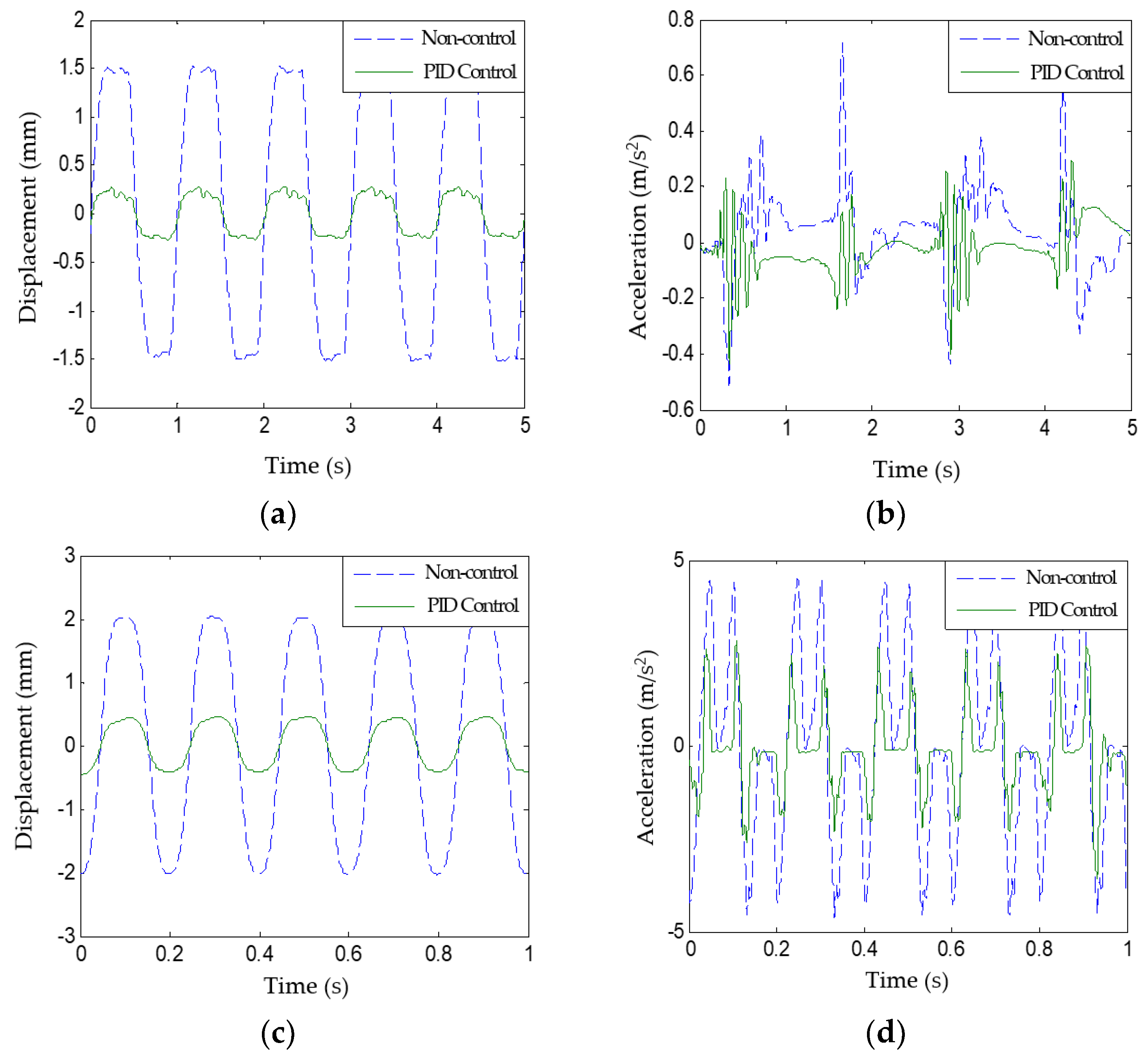
4.4. PID Vibration Control Experiment

When the sinusoidal excitation frequencies are 1 Hz, 5 Hz, and 10 Hz, the vibration response test results of the pipeline under the PID vibration control are shown in Figure 15. When the vibration control of the pipeline is controlled by the PID vibration control, the statistical results of the vibration response of the pipeline under different excitation frequencies are shown in Table 3.
As shown in Table 3, when the vibration of the pipeline is controlled by the PID control, the displacement and acceleration of the pipeline are significantly reduced. As shown in Table 3, the displacement drop of the pipeline vibration at different excitation frequencies ranges from 12.9361 to 22.3107 dB, the acceleration drop range is from 4.6154 to 16.3444 dB, the displacement attenuation range is from 77.45% to 92.34%, and the acceleration attenuation range is from 41.22% to 84.77%, and the vibration isolation rate ranges from 86.74% to 98.83%.

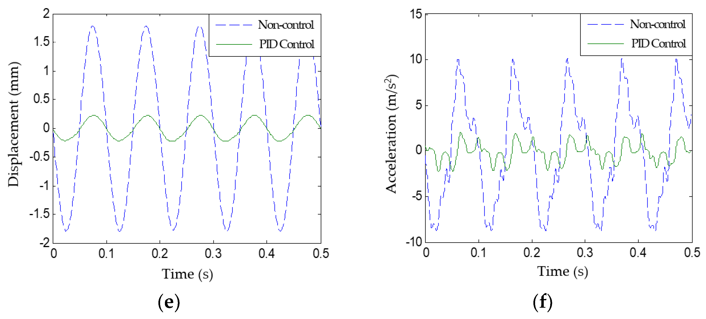
4.5. SMVS Vibration Control Experiment

When the sinusoidal excitation frequencies are 1 Hz, 5 Hz, and 10 Hz, the vibration response test results of the pipeline under the SMVS vibration control are shown in Figure 16. When the vibration control of the pipeline is controlled by the SMVS vibration control, the statistical results of the vibration response of the pipeline under different excitation frequencies are shown in Table 4.
As shown in Table 4, when the vibration of the pipeline is controlled by the SMVS control, the displacement and acceleration of the pipeline are significantly reduced. As shown in Table 4, the displacement drop of the pipeline vibration at different excitation frequencies ranges from 10.2215–17.9017 dB, the acceleration drop range is 1.2689–14.4325 dB, the displacement attenuation range is 69.17–87.27%, and the acceleration attenuation range is 13.59–81.02%, and the vibration isolation rate ranges from 84.80–96.87%.

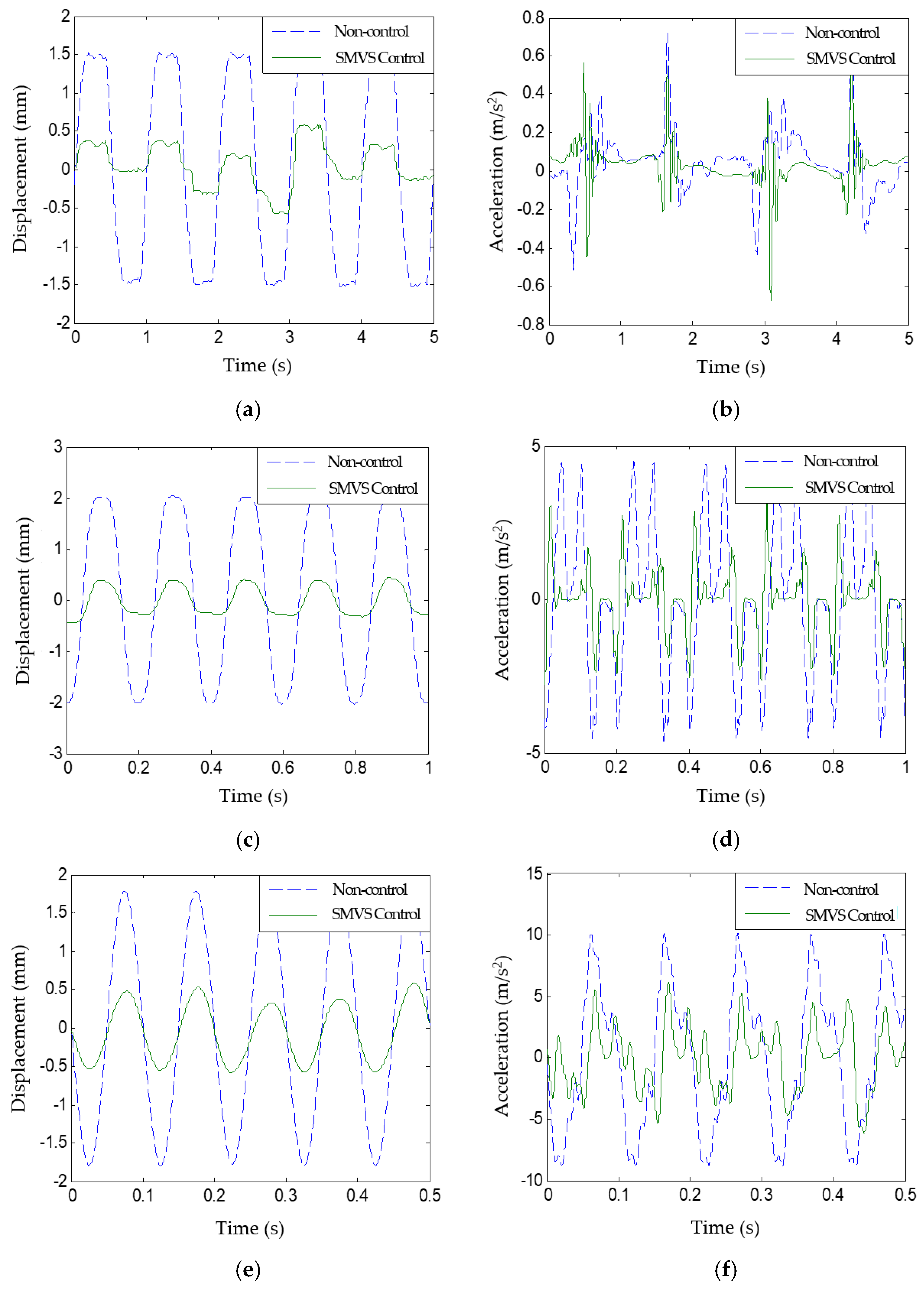
5. Results and Discussions

The RMS of displacement and acceleration of the controlled and without controlled pipeline are shown in Figure 17. It can be seen that, all three control methods can effectively control pipeline vibration. When the vibration frequency is 1 Hz, 2 Hz, 5 Hz and 8 Hz, the control effect of PID on displacement and acceleration is better than the other two control methods. When the vibration frequency is 3 Hz, 4 Hz, 9 Hz and 10 Hz, the control effect of SMVS on displacement and acceleration is better than the other two control methods.
The vibration characteristics such as level drop and vibration attenuation rates of the different pipeline vibration control modes are shown in Figure 18. It can be seen that, the three pipeline vibration control methods have better control effects on displacement than acceleration. To comprehensively evaluate the control effect of each control mode on pipeline vibration, the average values of the vibration level difference of the three control modes are shown in Table 5.
The statistical results (shown in Table 5) exhibit that all three semi-active vibration control methods can effectively reduce pipeline vibration, and the simulation results are in basic agreement with the experimental results. SMVS vibration control mode has the best suppression effect on the amplitude and acceleration of pipeline vibration, while PID control is only inferior to SMVS control in the effect of pipeline vibration control.

6. Conclusions

In this paper, the key technology of semi-active control of pipeline vibration based on MR damper was studied. The prototype of MR damper was developed, the dynamic loading test of the prototype was carried out and the dynamic model of MR damper was established. The mechanism of pipeline vibration and the pipeline vibration control algorithm based on MR damper were discussed. The semi-active vibration measurement and control platform based on MR damper was built. The vibration control performances of different pipeline vibration control algorithms were studied experimentally. The conclusions are as follows:
(1)
The transient response of the pipeline system with two-state control has a higher amplitude than the uncontrolled piping system. When the vibration amplitude of the pipeline is equal to the minimum limit of the two-state vibration control, the system exhibits a brief chattering, and the transient process time of the controlled pipeline system is basically the same as that of the uncontrolled system.
(2)
PID vibration control can effectively control the pipeline vibration during transient phase without system instability and amplitude overshoot. However, when PID vibration control is adopted, the MR damper damping force output has strong pulse characteristics, which will cause a large impact on the MR damper drive control system.
(3)
In the transient stage, the vibration amplitude of SMVS vibration control system is larger than that of PID vibration control system. In the steady-state stage, SMVS vibration control effect is better than that of PID control, and the continuity of SMVS vibration control force is better than that of PID control and two-state control.
(4)
The experimental results show that the SMVS vibration control method has the best control effect on the pipeline amplitude and acceleration. The average drop of pipeline displacement is 18.60 dB, the average deviation of acceleration is 13.10 dB, the average attenuation rate of displacement is 87.89%, the average attenuation rate of acceleration is 71.68%, and the average vibration isolation rate is 96.58%.

Author Contributions

Conceptualization, H.J., S.N. and Z.D.; data curation, Y.H. and F.Y.; formal analysis, F.Y.; investigation, H.J., Y.H. and F.Y.; methodology, Z.D.; project administration, S.N.; supervision, S.N.; validation, Y.H. and F.Y.; writing—original draft, H.J.; writing—review and editing, S.N. and Z.D. All authors have read and agreed to the published version of the manuscript.

Funding

This research was funded by the Beijing Natural Science Foundation (Grant No. 3182003), National Natural Science Foundation of China (Grant Nos. 51905011 and 51975010), Beijing Municipal Science and Technology Project (Grant Nos. KM201810005014 and KM201910005033), and CSIC Key Laboratory of Thermal Power Technology Open Foundation (Grant No. TPL2017BB010).

Acknowledgments

Thanks are given to Dekui Xin and Lianwei Li for their help in prototype design, simulation, experiment and polishing of the manuscript.

Conflicts of Interest

The authors declare no conflict of interest.

References

  1. Quan, L.; Kong, X.; Bin, Y.U.; Bai, H. Research status and trends on fluid-structure interaction vibration mechanism and control of hydraulic pipeline. J. Mech. Eng. 2015, 51, 175–183. [Google Scholar] [CrossRef]
  2. Yin, Z.Y.; Zhong, R.; Liu, Z.Z. Current situation and trends on the study of noise and vibration control technology in pipeline systems. Ship Sci. Technol. 2006, 28, 23–29. [Google Scholar]
  3. Beketov, S.B.; Kunina, P.S.; Bunyakin, A.V.; Dubov, V.V. Failure of industrial pipelines due to low-frequency vibrations. Russ. J. Nondestruct. Test. 2017, 53, 669–676. [Google Scholar] [CrossRef]
  4. Wang, H.L.; Zhang, N.; Cao, D. Finite element analysis for coupling vibrations of liquid-filled pipe and support structure system. Appl. Mech. Mater. 2013, 330, 677–680. [Google Scholar] [CrossRef]
  5. Sheng, Z.; Yi, R.; Taotao, C.; Shuiying, Z. Vibration suppression of pipe system with tuned mass damper. J. Vib. Meas. Diagn. 2012, 32, 823–826. [Google Scholar]
  6. Lu, J.; He, L.D.; Hu, P. Experimental study of the reduction in the wide frequency band vibration of a pipeline using a tuned mass damper. J. Beijing Univ. Chem. Technol. (Nat. Sci. Ed.) 2015, 42, 102–106. [Google Scholar]
  7. Wang, W.C.; Yin, Z.Y.; Chen, K.; Yang, S.L. Research on design method for a new type 3D pipeline damper. J. Ship Mech. 2015, 19, 191–197. [Google Scholar] [CrossRef]
  8. Li, H.N.; Zhang, P.; Song, G.B. Robustness study of the pounding tuned mass damper for vibration control of subsea jumpers. Smart Mater. Struct. 2015, 24, 1–12. [Google Scholar] [CrossRef]
  9. Song, G.B.; Zhang, P.; Li, L.Y. Vibration control of a pipeline structure using pounding tuned mass damper. J. Eng. Mech. 2016, 142, 1–10. [Google Scholar] [CrossRef]
  10. Kiyar, M.B.; Johnson, M.; Fuller, C. Experiments on the active control of multiple wave types in fluid filled piping systems. ASME Int. Mech. Eng. Congr. Expo. 2002, 3, 33–41. [Google Scholar]
  11. Kartha, C.S. Active, Passive and Active/Passive Control Techniques for Reduction of Vibrational Power Flow in Fluid Filled Pipes. Ph.D. Thesis, Virginia Polytechnic Institute and State University, Blacksburg, VA, USA, 2000; pp. 25–38. [Google Scholar]
  12. Yau, C.H.; Bajaj, A.K.; Nwokah, O.D. Active control of chaotic vibration in a constrained flexible pipe conveying fluid. Am. Soc. Mech. Eng. 1992, 9, 93–108. [Google Scholar] [CrossRef]
  13. Chen, S.S.; Ma, Y.Q. Seismic responses of isolated continuous girder bridges based on hybrid control of MRD and LRB. J. Beijing Univ. Technol. 2013, 39, 378–384. [Google Scholar]
  14. Rama, R.K.; Vineeth, V.D. Developments in vibration control of structures and structural components with magnetorheological fluids. Curr. Sci. 2017, 122, 499–508. [Google Scholar] [CrossRef]
  15. René, Z.; Juan, C.; Hernaldo, S. Development of a long-stroke MR damper for a building with tuned masses. Smart Mater. Struct. 2016, 25, 101–106. [Google Scholar]
  16. Heo, G.; Kim, C.; Lee, C. Experimental test of asymmetrical cable-stayed bridges using MR-damper for vibration control. Soil Dyn. Earthq. Eng. 2014, 57, 78–85. [Google Scholar] [CrossRef]
  17. Xin, D.K.; Nie, S.L.; Ji, H.; Yin, F.L. Characteristics, optimal design, and performance analyses of MRF damper. Shock Vib. 2018, 6, 1–17. [Google Scholar]
  18. Nie, S.L.; Xin, D.K.; Ji, H.; Yin, F.L. Optimization and performance analysis of magnetorheological fluid damper considering different piston configurations. J. Intell. Mater. Syst. Struct. 2019, 30, 764–777. [Google Scholar] [CrossRef]
  19. Li, X.L.; Li, H.N. Double-sigmoid model for magnetorheological damper and corresponding experiment verification. J. Vib. Eng. 2006, 19, 168–172. [Google Scholar]
  20. Ji, C.Y.; Zhi, G.X.; Wang, Y.; Cui, J. Study on design principles for the impact resistant piping system. Ship Ocean Eng. 2015, 44, 112–116. [Google Scholar]
Figure 1. Schematic diagram of pipeline vibration control system based on a magneto-rheological (MR) damper: (a) Structural diagram; (b) Control block diagram.
Applsci 10 02541 g001
Figure 2. MR damper prototype and damping force testing platform.
Applsci 10 02541 g002
Figure 3. Dynamic characteristics of the MR damper: (a) Force-displacement curve; (b) Force-velocity curve.
Applsci 10 02541 g003
Figure 4. Genetic algorithm of parameter identification for the double-sigmoid model: (a) Flow chart of genetic algorithm; (b) Genetic algorithm toolbox.
Applsci 10 02541 g004
Figure 5. Dynamic characteristics of MR damper under control current of 0, 2, 4 A: (a) Force-displacement curve (0 A); (b) Force-velocity curve (0 A); (c) Force-displacement curve (2 A); (d) Force-velocity curve (2 A); (e) Force-displacement curve (4 A); (f) Force-velocity curve (4 A).
Applsci 10 02541 g005aApplsci 10 02541 g005b
Figure 6. Schematic diagram of pipeline system.
Applsci 10 02541 g006
Figure 7. Simulation of two-state pipeline vibration control system with dead zone: (a) Two-state simulation model; (b) Vibration displacement response; (c) Control force and disturbance dynamics curve.
Applsci 10 02541 g007
Figure 8. Simulation of PID pipeline vibration control system: (a) PID simulation model; (b) Vibration displacement response; (c) Control force and disturbance dynamics curve.
Applsci 10 02541 g008
Figure 9. Simulation of sliding-mode-variable-structure (SMVS) pipeline vibration control system: (a) Sliding-mode-variable-structure (SMVS) simulation model; (b) Vibration displacement response; (c) Control force and disturbance dynamics curve.
Applsci 10 02541 g009
Figure 10. Pipeline vibration measurement and control system based on MR damper.
Applsci 10 02541 g010
Figure 11. Pipeline vibration measurement and control system.
Applsci 10 02541 g011
Figure 12. Pipeline vibration response under sinusoidal excitation frequency of 1, 5, 10 Hz without control: (a) Displacement-time curve (1 Hz); (b) Acceleration-time curve (1 Hz); (c) Displacement-time curve (5 Hz); (d) Acceleration-time curve (5 Hz); (e) Displacement-time curve (10 Hz); (f) Acceleration-time curve (10 Hz).
Applsci 10 02541 g012
Figure 13. Two-state control diagram.
Applsci 10 02541 g013
Figure 14. Pipeline vibration response under two-state control and excitation frequency of 1, 5, 10 Hz: (a) Displacement-time curve (1 Hz); (b) Acceleration-time curve (1 Hz); (c) Displacement-time curve (5 Hz); (d) Acceleration-time curve (5 Hz); (e) Displacement-time curve (10 Hz); (f) Acceleration-time curve (10 Hz).
Applsci 10 02541 g014
Figure 15. Pipeline vibration response under PID control and excitation frequency of 1, 5, 10 Hz: (a) Displacement-time curve (1 Hz); (b) Acceleration-time curve (1 Hz); (c) Displacement-time curve (5 Hz); (d) Acceleration-time curve (5 Hz); (e) Displacement-time curve (10 Hz); (f) Acceleration-time curve (10 Hz).
Applsci 10 02541 g015aApplsci 10 02541 g015b
Figure 16. Pipeline vibration response under SMVS control and excitation frequency of 1, 5, 10 Hz: (a) Displacement-time curve (1 Hz); (b) Acceleration-time curve (1 Hz); (c) Displacement-time curve (5 Hz); (d) Acceleration-time curve (5 Hz); (e) Displacement-time curve (10 Hz); (f) Acceleration-time curve (10 Hz).
Applsci 10 02541 g016
Figure 17. RMS of displacement and acceleration: (a) Displacement; (b) Acceleration.
Applsci 10 02541 g017
Figure 18. Vibration characteristics of the different pipeline vibration control modes: (a) Vibration level difference of displacement; (b) Vibration level difference of acceleration; (c) Attenuation rate of displacement; (d) Attenuation rate of acceleration.
Applsci 10 02541 g018
Table 1. Vibration response of the pipeline without control.
Frequency (Hz)DisplacementAcceleration
Peak Value (mm)RMS (mm)Peak Value (m/s2)RMS (m/s2)
11.62401.30770.65110.1729
21.80371.46681.59920.5786
31.90091.54442.50291.1008
41.97391.59133.87431.7155
52.09931.66754.71602.5321
62.24291.68876.41043.3078
72.35051.76099.41704.2914
82.17821.62778.66294.7947
92.23351.532310.66745.5253
102.29671.52929.77455.8046
Table 2. Vibration response of pipeline under two-state pipeline vibration control.
Frequency (Hz)Displacement (mm)Acceleration (m/s2)
RMS (mm)Difference (dB)AttenuationRMS (m/s2)Difference (dB)Attenuation
10.104721.931291.99%0.08955.719448.24%
20.165718.941088.70%0.19289.545466.68%
30.287914.590481.36%0.65804.469740.23%
40.222917.072885.99%0.59589.185865.27%
50.170519.806889.78%0.686111.341972.90%
60.200318.517488.14%0.771112.648676.69%
70.280515.956084.07%1.37029.916368.07%
80.149120.761990.84%0.898514.544981.26%
90.273014.983682.18%1.96068.999364.52%
100.197317.786787.10%1.424612.201675.46%
Table 3. Vibration response of pipeline under PID pipeline vibration control.
Frequency (Hz)DisplacementAcceleration
RMS (mm)Difference (dB)AttenuationRMS (m/s2)Difference (dB)Attenuation
10.219615.497583.21%0.09924.825742.63%
20.330812.936177.45%0.34014.615441.22%
30.120522.155592.20%0.295211.431873.18%
40.137221.288091.38%0.391312.837677.19%
50.348513.597379.10%1.04437.693158.76%
60.203418.384087.96%0.978510.579670.42%
70.199418.920288.68%1.121511.656073.87%
80.167819.735689.69%0.982613.767779.51%
90.139220.834190.92%1.106513.968179.97%
100.117222.310792.34%0.884216.344484.77%
Table 4. Vibration response of pipeline under SMVS control.
Frequency (Hz)DisplacementAcceleration
RMS (mm)Difference (dB)AttenuationRMS (m/s2)Difference (dB)Attenuation
10.230115.091882.40%0.14941.268913.59%
20.256615.142382.51%0.30825.470946.73%
30.314913.811779.61%0.67724.219838.48%
40.231816.732885.43%0.71797.566558.15%
50.271915.753183.69%0.98288.220361.19%
60.256116.382984.83%1.13879.262665.58%
70.277116.062084.26%1.39109.785467.59%
80.268815.642983.49%0.910214.432581.02%
90.195117.901787.27%2.23437.864359.56%
100.471410.221569.17%2.66756.753454.05%
Table 5. Vibration level difference of the three control methods.
Method L x   ( dB ) L a   ( dB ) J x J a J e
Two-state15.27 dB8.34 dB82.27%54.59%91.77%
PID18.04 dB9.86 dB87.01%65.93%95.28%
SMVS18.57 dB10.77 dB87.29%68.15%95.43%

