1. Introduction
The International Council on Systems Engineering (INCOSE) defines Model-Based System Engineering (MBSE) as the formalized application of modeling to support system requirements, design, analysis, verification, and validation activities beginning in the conceptual design phase and continuing throughout development and later life cycle phases [
1]. Today, MBSE and the SysML language have become an indispensable part of designing complex cyber-physical systems [
2,
3,
4]. The reasons for their popularity are [
1,
2,
3,
4]:
MBSE gives a standardized way of capturing and managing the system’s requirements, architecture, design, and processes, as well as identifying its environment (System of Systems).
Facilitates communication among various stakeholders by providing discipline-specific views for different purposes (e.g., requirements, logical system view, physical system view).
Allows detecting defects early in the system development life cycle.
Allows comparing and simulating “As Is” and “To Be” solutions.
Can serve as a single source of truth for systems engineers and other team members.
Allows exploring multiple solutions with minimal investment.
The authors agree that the biggest value from MBSE activities is gained when system validation and verification are performed at the early phase of system design, especially in terms of change cost [
5,
6]. In such a case, the defects could be fixed with less impact and prevented rework in later phases, thus mitigating uncertainties to cost and schedule [
6]. The same principles apply in the security field: the risk identification and mitigation are the most effective and maximize the return on investment if it is integrated into the design process and utilized in the early stages [
7]. There are several tools and methods that allow performing security analysis at the initial phase of systems creation (e.g., Misuse Cases, Abuse Cases, Secure-Tropos, combined harm assessment of safety and security for information systems (CHASSIS)); however, they are disjointed from the systems engineering [
8,
9].
In this paper, we present an analysis of various techniques for defining the security aspect and then clarify how these techniques can be represented in Unified Modeling Language (UML) and SysML models and then further exploited with MBSE tools (such as simulation, validation, and verification). As a result, the MBSEsec method is introduced, which allows cross-functional (systems and security) teams to perform security analysis in parallel to the systems engineering process at an early stage of system creation. The MBSEsec method is verified by expanding the Hybrid Sport Utility Vehicle SysML model with four security mitigation phases and running an experiment where systems and security engineers evaluate its correctness, completeness, and learning time.
2. Analysis of Related Work
This section presents an overview of the International Organization for Standardization (ISO) (ISO) and the and the International Electrotechnical Commission (IEC) 27001 information security standard, which allows systematically governing risks for the systems under design. The next section, Modeling approaches and techniques for security analysis, demonstrates how the security question is tackled in the different systems modeling methods, and how the specific security techniques can be integrated into the MBSE process.
2.1. Overview of ISO/IEC 27001
The ISO/IEC 27001 standard by the International Organization for Standardization (ISO) and the International Electrotechnical Commission (IEC) specifies the requirements for establishing, implementing, operating, monitoring, reviewing, maintaining, and improving information security management system (ISMS) [
10]. The security standard assists in the task of developing secure complex systems in the following ways:
It gives a step-by-step approach to establish ISMS [
10,
11,
12].
It provides best practice recommendations on information security management, risks, and controls [
10].
In our previous paper, we presented the SysML/UML-based MBSE security profile that conforms to the ISO/IEC 27001 standard [
12]. The ISO/IEC 27001 4.2.1 section provides foundational steps for managing risks at a very high level, and these steps are the subject of the system engineering workflow at an early stage. The process that should be captured in the MBSE model is as follows:
Define the risk assessment approach of the organization.
Identify the risks.
Analyze and evaluate the risks.
Identify and evaluate options for the treatment of risks.
Select control objectives and controls for the treatment of risks.
One of the biggest MBSE returns on investment is that by validating and verifying system characteristics early, it enables fast feedback on requirements and design decisions [
5,
6]. This leads to the conclusion that the security solution should be lean, too. The ISO/IEC 27001 standard adopts the “Plan–Do–Check–Act” (PDCA) model (
Figure 1), which dictates that the ISMS should be continuously improved, and this principle suits the systems engineering process very well [
10].
Our main objective is to develop a feasible and efficient MBSE method for creating secure systems while respecting ISO/IEC 27001 requirements.
2.2. Modeling Approaches and Techniques for Security Analysis
This section presents the modeling approaches and techniques for security analysis and risk mitigation. The initial analysis of these approaches was presented in previous work [
12]; in this paper, we look further into how the security techniques can be integrated into the MBSE model and further exploited with system engineering tools (e.g., simulation, validation, and verification). The following approaches that are based on the UML/SysML syntax are analyzed in this paper:
2.2.1. Unified Architecture Framework (UAF)
UAF is a modeling framework that defines ways of representing an enterprise architecture. UAF could be used throughout the entire system life cycle, starting with the initial concept, requirements, design specification phases, continuing with the implementation, deployment phases, and finishing with operations, maintenance, and disposal phases. The UAF architecture models allow users to model the complex relationships that exist between organizations, systems, and systems-of-systems, and they also enable the analysis of these systems to ensure that they meet the stakeholder needs. The framework enables the modeling of security, including cybersecurity controls as well [
13,
14].
The UAF syntax is based upon a combination and extension of UML and SysML elements and diagrams. For example, the security processes view represents the security controls that are necessary to protect organizations, systems, and information during processing. The recommended implementation for these security controls is the enhanced SysML Activity diagram [
13].
Key techniques for defining security aspects: security constraints definition, security processes definition, security structure definition.
Integration to MBSE process: UAF supports the capability to model enterprise architecture (strategy, operational, personnel and resources, project, and security) and, optionally, trace it with the systems-level model(s), which is modeled with SysML or UML languages.
2.2.2. CHASSIS
The CHASSIS method defines a process for security and safety assessments to address both the security and safety aspects during the system development process. The main CHASSIS techniques are UML-based diagrams as well as traditional text-based techniques such as Hazard and Operability study (HAZOP) or security requirements specification [
9,
15].
There are three main steps in the CHASSIS method: eliciting functional requirements; eliciting safety/security requirements; and specifying safety/security requirements. The first two steps rely on creating and analyzing UML-based diagrams (use case, sequence, misuse case, misuse sequence). The third steps suggest conducting results in the HAZOP table and in security/safety requirements specification [
15].
Key techniques for defining security aspects: Misuse cases, misuse case sequence diagram, HAZOP, security requirements.
Integration to MBSE process: The CHASSIS method presents a process definition, not a dedicated UML/SysML profile. As the CHASSIS method suggests using UML-based diagrams, the principles of it can be adapted to the MBSE process.
2.2.3. UML Sec
UML Sec is a lightweight extension to the UML language for integrating security-related information in UML models. The UML Sec approach does not introduce additional security diagrams but provides a UML profile with stereotypes and constraints. The UML Sec stereotypes allow users to define security requirements and model attack/failure scenarios with existing UML diagrams (e.g., Use Case, Activity, Sequence diagrams). The constraints (Object Constraint Language (OCL) validation rules) enable users to verify the model with formal semantics [
16,
17]. In addition, the UML Sec extension can be used with the Goal-Driven Security Requirements Engineering methodology to have a structured framework for secure software systems creation [
18].
Key techniques for defining security aspects: Security requirements, failure/attack scenarios.
Integration to MBSE process: UML Sec is a lightweight extension for UML, so the security-related stereotypes can be used within SysML models; however, no default traceability or mapping is defined.
2.2.4. SysML Sec Methodology
SysML Sec is a model-driven engineering approach for creating secure embedded systems. This methodology presents semi-formal specifications of both security and safety features and properties at various development cycle phases [
19].
The SysML Sec methodology has three stages: analysis, design, and validation. The analysis stage covers security requirements and attack scenarios; it also serves as an identification of the main functions and candidate system architecture. In the system design phase, security requirements are refined with security properties, and security-related functions are defined. The validation stage gives users a formal assessment of whether security properties are valid and verified [
19].
In the SysML Sec methodology, security requirements are based on an extended SysML Requirement diagram. A new security requirement stereotype with the property of Kind (e.g., confidentiality, access control, integrity, freshness) allows users to distinguish security requirements from functional and non-functional requirements. Attack trees can be specified with a customized SysML Parametric diagram. A Formal Dolev-Yao attacker model (for describing attacks on the protocols deployed between the components of the embedded system model) can be modeled with extended SysML Block and State Machine diagrams [
20].
Key techniques for defining security aspects: Requirement diagrams, attack scenarios, Dolev–Yao attacker model.
Integration to MBSE process: SysML Sec was created to support all methodological stages of the design and development of embedded real-time systems. As SysML Sec uses extended SysML diagrams for capturing security concerns, the principles of it can be adapted to the MBSE process.
2.3. Security Techniques Comparison
This section is dedicated to aligning the modeling approaches and techniques for security analysis. We present which security-related techniques overlap between analyzed modeling approaches and how these techniques are implemented in the SysML language in
Table 1 (Y indicates that the corresponding technique is used in the modeling approach, and N means that it is not relevant).
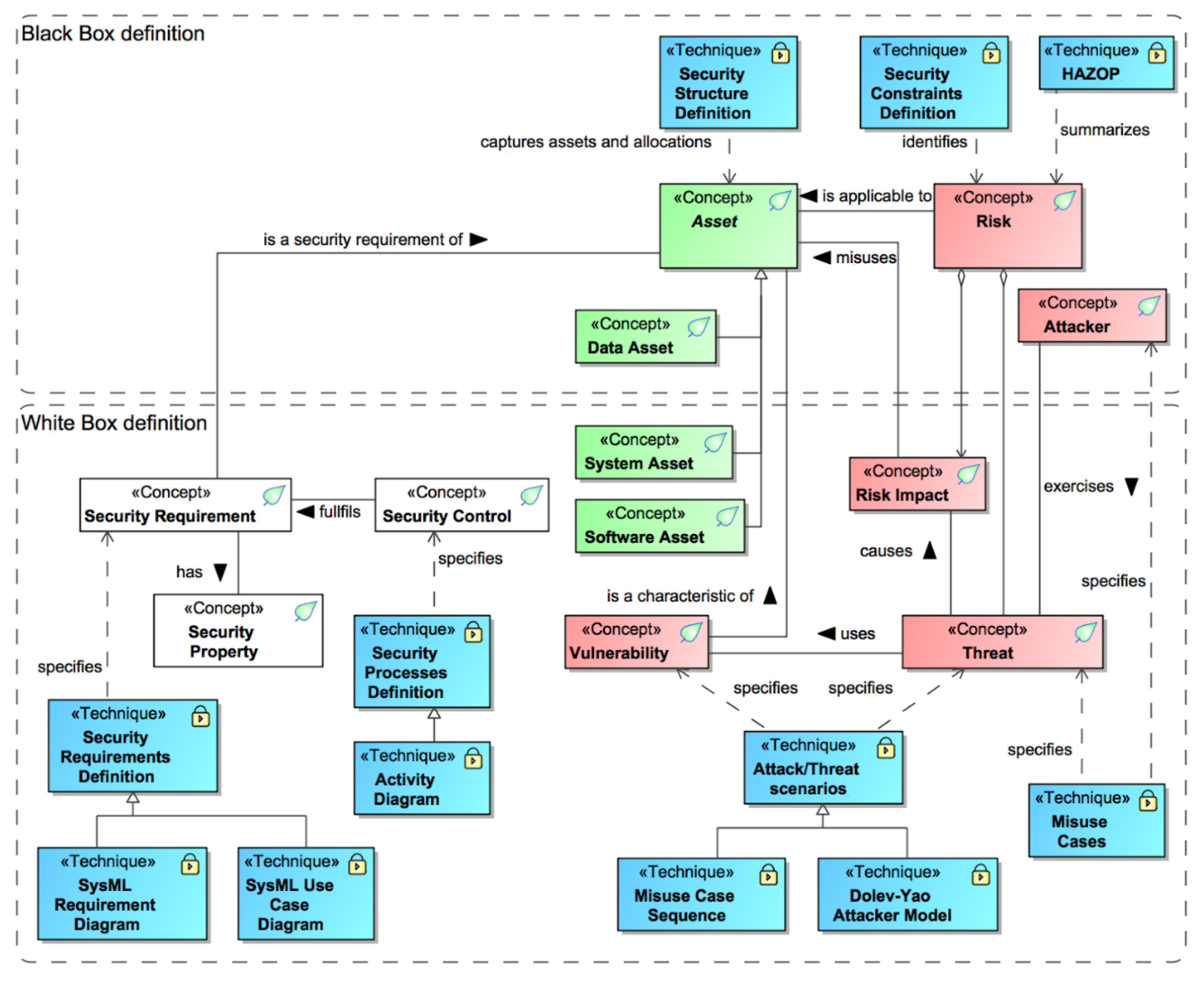
The initial security domain model with security concepts was presented in the previous article [
12]. Now, we are adding security techniques and linking them with security concepts. In
Figure 2, all the new security-related techniques are marked with the <<Technique>> stereotype (shapes filled with blue color) and linked with the concepts. The relationship name describes how a specific concept should be treated with the corresponding security technique.
3. MBSEsec Method
This section introduces the MBSEsec method, which covers activities and guidelines for creating secure systems with the SysML security profile.
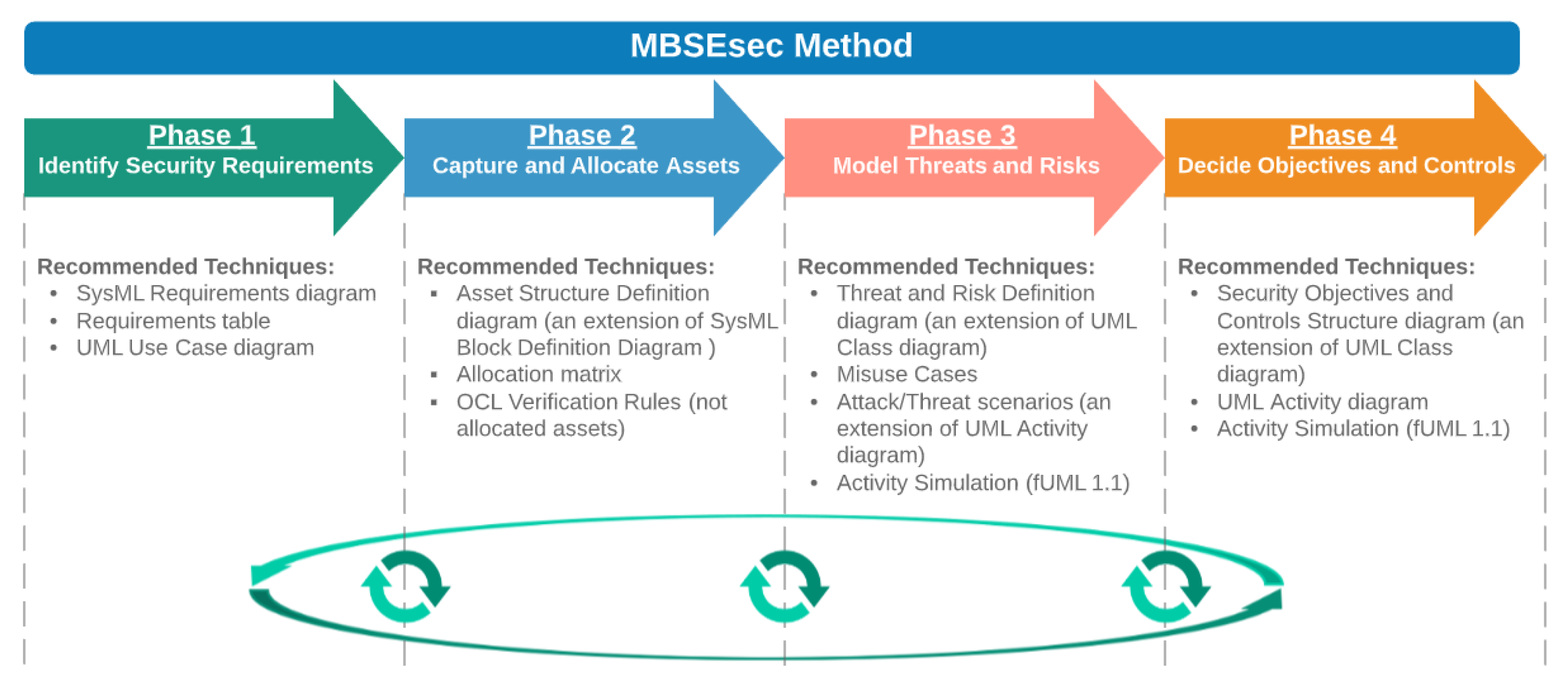
Figure 3 shows the phases and underlying security techniques of the MBSEsec method. Some of the activities that are suggested in the MBSEsec method directly match the name and definition of the security technique from the analysis part (e.g., Misuse Cases, SysML Requirements Diagram); some of them are derived (e.g., Asset Structure Definition, Threat and Risk Definition). The third part of the techniques falls into the MBSE features category (e.g., verification rules, activity simulation, allocation matrix). In order to apply these techniques, we regrouped and expanded the SysML Security profile (see
Figure 4), which originally was introduced in [
12].
Phase 1—Identify Security Requirements. The starting point of the MBSEsec method is to identify the security requirements as an additional part of the functional and non-functional requirements that are usually captured at an early stage of SE model creation. We have expanded the initial security profile with the “Security Requirement” stereotype, which is a subtype of the SysML Requirement (see
Figure 4). We recommend using the standard SysML Requirements diagram or Requirements table for capturing security requirements. The further security requirement refinement can be additionally done with the SysML/UML Use Case diagram.
Phase 2—Capture and Allocate Assets. The second phase is dedicated to defining the objects that the organization should secure and allocate them to the system’s parts. The SysML language has two concepts for defining system structural elements: Blocks that define types, and Parts that represent the usage of these blocks in a specific context. Similarly, the assets definition can be performed in both ways; however, the goal of this phase is to represent the structure, not the usage or internal connections. As a result, we recommend using a new diagram type of Asset Structure Definition, which should be an extension of the Block Definition Diagram. After the identification of the assets, Systems Blocks and Assets should be linked with the SysML Allocation relationship. This would allow us to create expressions based on Object Constraint Language (OCL) or other programming languages for running quantitative model verification, i.e., finding all the system blocks that are not allocated to any asset element.
Phase 3—Model Threats and Risks. This phase consists of two parts: behavioral and structural security specification. For the behavioral risk and threat definition, we recommend the extended Use Case diagram for identifying Misuse Cases and the UML Activity diagram for modeling Attack Scenarios. The Dolev–Yao attacker model was mentioned in the literature analysis; however, this technique is too detailed for an early phase, and we do not include it in the MBSEsec method. The Dolev–Yao attacker model can be applied in the later phases or when formal verification is needed. For the structural risk definition, we recommend the new Threat and Risk Definition diagram, which should be based on the UML Class diagram. In this diagram, the following elements should be created and linked: Risk; Risk Treatment; Risk Impact; Threat; and Vulnerability. Alternatively, a HAZOP style table can be used to summarize risk-related information.
Phase 4—Decide Objectives and Controls. The final phase helps us to define security control objectives and controls. We recommend using a new Security Objectives and Controls Structure diagram (an extension of the UML Class diagram) for defining elements of security objectives and controls. The standard UML Activity Diagram could be used for identifying workflow or algorithm for security control. We recommend modeling security workflow by following fUML1.1. standard; this would allow security engineers to simulate and verify security controls.
The phases of the MBSEsec approach should not necessarily be conducted consecutively. We suggest following the PDCA model, in which the outcomes of MBSEsec phases should be continuously reviewed and updated after each phase; i.e., it is recommended to update the Risk Treatment in the Threat and Risk Definition diagram (in Phase 3) after identifying the Security Controls in Phase 4.
The next section presents how the MBSEsec method can be applied in the real-world SysML model.
4. Applying the MBSEsec Method
To demonstrate the MBSEsec method usage, we selected the Hybrid Sport Utility Vehicle (HSUV) model from the OMG SysML specification [
21,
22]. A modern vehicle is subject to cyber attacks through its various network interfaces to the public network infrastructure as well as its direct exposure to the open physical environment [
23]. As identified by [
24], there are many vehicle parts and components that can be attacked (see
Figure 5); nevertheless, in our case study, we are focusing on the Power Control Electronic Control Unit (ECU) and presenting how the security issues for this component can be identified, analyzed, and mitigated.
Before starting a security analysis, security engineers should ensure that the risk assessment methodology and criteria for accepting risks are set. The methodology can be captured in the “Risk Assessment Configuration” model element as documentation or link to the document. The “Criteria for Accepting Risks” should be set as an integer number.
The first phase of “Identify Security Requirements” suggests that the security requirements should be identified, captured, and refined in the MBSE model. Ideally, engineers who are working in the security requirements engineering discipline should combine expertise in security, domain, and requirements engineering fields to provide a foundation for developing a secure system [
25]. Depending on the novelty of the system, the expertise of the security engineer, and the security requirements engineering methodology, the security requirements can be very precise or more abstract. For the Power Control ECU part, we capture explicit security requirements, which dictates that external access to the ECU shall be limited (see
Figure 6). If there is a need, the security requirements can be refined with the SysML Use Case diagram.
In the second phase of “Capture and Allocate Assets”, we identify Power Control ECU Hardware, Embedded Software, and its Interface as assets that must be secured. As mentioned in the previous section, the assets should be created in Asset Definition Diagram. In the follow-up step, we should link these assets with the systems blocks with the SysML Allocate relationship. The relation map diagram (see
Figure 7) presents the system structure (as columns) and assets (as rows), while the arrow in the intersection represents either direct or indirect allocation.
In the “Model Risks and Threats” phase, we reflect an experiment conducted by [
22], in which a long-range wireless cyber attack was physically tested using a real vehicle and malicious mobile application in a connected car environment. Initially, we need to model the high-level attack steps and the involved actors with the Misuse Case diagram, as shown in
Figure 8.
Then, we can model the more detailed attack scenario with the SysML Activity diagram (see
Figure 9). The first swimlane presents a sequence of actions performed by the malicious app, and other swimlanes represent the parts of the HSUV and what actions are invoked in each partition. As a result of this attack scenario, the vehicle has a possible fatal malfunction caused by the abnormal control data that was transmitted from the malicious app. If the activity diagram is modeled according to the fUML1.1. standard, then the correctness of the attack scenario can be verified by running activity simulation (i.e., using MagicDraw modeling tool with the Simulation toolkit plugin).
For the final step in the “Model Risks and Threats” phase, we need to create the
Threat and Risk Definition diagram in which Risk, Risk Impact, Threat, and Vulnerability should be modeled. Respectively, we capture the risk of “An attacker is able to take over a Power Control ECU via the OBD-II port, reprogram it, and execute functions of Power Subsystem”, which has the risk impact of “Lost control of HSUV acceleration”. The possible threat is “Fault injection on automotive diagnostic protocols” that potentially uses the vulnerability of “Control Area Network (CAN) protocol”. The Threat and Risk definition diagram with all the relevant security elements and relations is presented in
Figure 10.
The “Decide Objectives and Controls” phase allows us to identify objectives for the security controls and define the risk mitigation controls. In our case, the possible objective can be Prevent Unauthorized Access to Power Control ECU. The security control, in the form of an activity diagram, should present a preventive algorithm and specific actions that would allow fulfilling the security control objective. As is shown in
Figure 11, the activity diagram presents multilayered protection that can be reused for the different ECUs. When we finish modeling the appropriate security control, we should not forget to create the Risk Treatment element and link it with Risk and Security Control.
Finally, when both MBSE and security elements are created and linked in the MBSE model, we can take advantage of the modeling tool and run an automated analysis. We provide possible questions for the security model completeness and supporting algorithms in
Table 2. These algorithms can be formatted to a specific programming language syntax (e.g., OCL 2.0, Javascript) and used as metrics or verification rules to evaluate the current state of the model.
The next automated assistance of MBSE is impact analysis. We can analyze which system and security elements shall be reviewed if the initial system requirement of “Power” is being changed. In
Figure 12, we present the relation map diagram that presents such traceability from requirements to the system and software assets.
5. Evaluation
In order to evaluate the feasibility of the MBSEsec method, we asked MBSE and security practitioners to answer questions related to their experience, work principles, and the security method itself. The questions were answered by various engineering organizations representatives (in total 15) and academic representatives (in total 4). The respondents’ disciplines were as follows: Systems Engineering (in total 9), Software Engineering (in total 6), Requirements Engineering (in total 3), and Mechanical Engineering (in total 1). All the respondents were aware of MBSE, and over half of the respondents were practicing MBSE for more than 5 years. The results are provided in
Figure 13.
Primarily, we wanted to find out the participants’ current work principles related to system development. For this, we asked if the respondents followed agile modeling practices with fast learning and validation cycles or if they preferred a linear approach (e.g., waterfall methodology). Most (68%) of respondents use agile methods, 22% used a hybrid approach, and 10% preferred the waterfall methodology. As the suggested MBSEsec method is based on the PDCA model, it should suit the majority of respondents’ practices. The next question in this group was related to checking if the security requirements are captured together with the functional and non-functional requirements in the MBSE model. Most (63%) respondents do this, and this leads to the conclusion that the considerations of system security are quite commonly made at the early stage of system development.
Next, we asked our respondents to evaluate the importance of security mitigation phases. Most of the participants said that the identification of parts of the system that could be vulnerable is very important or important. More than half of the participants agreed that all the other mentioned security phases are important or very important, too. All the results are provided in
Figure 14.
Furthermore, we asked if the respondents see any other security phases/activities (not mentioned in the previous question) that should be conducted at the early stage of system development; here are the opinions:
It’s not only important to identify parts themselves that could be vulnerable but also their interaction/communication/links with other parts.
Information exchange analysis.
Embed security controls into the processes at all levels.
Calculate vulnerability scores (e.g., CVSS), link security aspects with rest of the design.
In terms of MBSE tools that would be the most suitable for running combined Systems and Security Engineering analysis, participants tended to agree that Representing information in different views (Diagrams, tables, matrices) and the Single source of truth are the most important. According to the respondents, the least important tool is Automated document generation. The detailed answers are provided in
Figure 15.
We also asked if the respondents could compare their efficiency when they moved from document-based system engineering to model-based system engineering. Most (63%) respondents said that their productivity increased, and the remaining said that productivity did not change, or it decreased. All the results are provided in
Figure 16.
Our next question was, “Did your work quality improve when you moved from document-based system engineering to model-based system engineering?” The majority of participants agreed that all the factors (Completeness; Consistency; Communication; Less defects) were improved. All the results are provided in
Figure 17.
The last evaluation objective was to find out the learning time required to start using the MBSEsec method. For this, we asked the following question: Can you approximately estimate how long it would take to learn to model 5 new UML/SysML-based diagrams that have 13 custom elements and 6 relations (assumption: you know domain knowledge very well, i.e., you do such analysis in Excel in your daily work)? More than half (53%) of respondents answered that it should take 2 to 5 days, while 26% indicated that it would take less than 2 days. Other participants had a different opinion; here are their answers:
It depends on how closely those new elements of the language map to the customer domain.
Assuming mastery in SysML, it will take 2 months to learn and use the new elements in production.
To summarize, our experiment showed that systems engineers see an importance in mitigating security risks with MBSE tools at an early stage of the system development life cycle. All the phases from the MBSEsec method (with some additions) are relevant and important for the respondents. The required learning time to learn additional security concepts is relatively low for practicing MBSE users, and it also brings bigger efficiency and better work quality.
6. Conclusions and Future Works
One way to increase the certainty in a complex system creation is to remove silos between systems engineering and security teams and tackle security risks during the systems engineering lifecycle. The literature analysis, previous research, and feasibility study showed that systems engineers and security engineers recognize the value of integrating security and system design processes; also, they agree that detecting security issues at the early stages of the development lifecycle helps to reduce the cost and risk of the engineering project.
This paper proposes the MBSEsec method for combining systems engineering and security engineering disciplines at an early stage in an efficient and model-based way. The MBSEsec method consists of the SysML/UML-based profile, security process definition, and recommendations on how the specific security technique should be implemented. The method covers phases starting from security requirements identification, continuing capturing assets and modeling threats and risks, and finally deciding security control objectives and appropriate controls. Furthermore, the MBSEsec method is aligned to the ISO/IEC 27001 information security standard.
The MBSEsec method usage was presented by extending the Hybrid Sport Utility Vehicle (HSUV) model from the OMG SysML specification. There was created the HSUV security model for the Power Control ECU that represented the phases from the MBSEsec method. The HSUV application case study proved that all the necessary security artifacts could be created in the SysML model (security requirements, misuse cases, asset structure definition, attack scenarios, threat and risk definition, security controls, and supporting matrices, relation maps, verification rules). The MBSEsec method principles and expectations were validated with system and security engineering practitioners. The participants agreed that the MBSEsec method could bring a better work quality in terms of completeness, consistency, and communication with comparatively small training effort.
We are planning to expand and update the MBSEsec approach according to the users’ feedback as well as research whether our method is appropriate for security issues identification while rebuilding legacy software systems.


