Article

Magnetoelectric Plasma Preparation of Silicon-Carbon Nanocomposite as Anode Material for Lithium Ion Batteries

1
College of Chemical Engineering, Fuzhou University, Fuzhou 350108, China
2
School of Engineering and Physical Sciences, Heriot-Watt University, Edinburgh EH14 4AS, UK
*
Author to whom correspondence should be addressed.
Appl. Sci. 2020, 10(8), 2672; https://doi.org/10.3390/app10082672
Submission received: 3 March 2020 / Revised: 27 March 2020 / Accepted: 1 April 2020 / Published: 13 April 2020
(This article belongs to the Special Issue Nanocomposite Materials: Synthesis, Properties and Applications)

Abstract

:
A high-performance silicon-carbon nanocomposite facilely prepared by one-step magnetoelectric plasma pyrolysis of the mixture of methane, silane, and hydrogen is proposed for lithium-ion batteries. The ratio of silane, methane, and hydrogen was studied to optimize the properties of the composite. When the ratio of hydrogen/silane/methane is 1:1:3, the composite is composed of spherical Si nanoparticles that uniformly attach to the surface of the tremelliform carbon nanosheets framework, in which the tremelliform carbon nanosheets can effectively resist the volumetric change of the Si nanoparticles during the cycles and serve as electronic channels. The silicon-carbon nanocomposite exhibits a high reversible capacity (1007 mAh g−1 after 50 cycles), a low charge transfer resistance, and an excellent rate performance. In addition, the proposed process for synthesizing silicon-carbon nanocomposite without expensive materials or toxic reagents is an environmentally friendly and cost-effective method for mass production.

1. Introduction

Nowadays, lithium-ion batteries (LIB) are the fastest developing energy storage systems, and have widespread application in mobile phones, laptops, electric vehicles, etc. [1,2,3]. However, the commercial graphite anode material has a limited theoretical capacity of 372 mAh g−1, which cannot meet the energy density requirements in certain applications [4,5]. Various studies have been carried out to find new high energy density materials, such as Sn- [6,7] or Si-based anodes [8,9,10], and transition metal oxides [11,12]. Among these, Si-based material is considered as a promising candidate owing to its high theoretical capacity of 4200 mAh g−1 [13,14]. At present, the main challenge is the enormous volumetric change of the Si during the cycle process, leading to structural failure and pulverization [15,16], and the low electronic conductivity of silicon also induces severe irreversible capacity loss.
At present, research has mainly focused on finding new Si-based structures to solve the problems of the volumetric changes. The utility of nanoparticles, nanosheets, nanohollows, nanowires, and nano-core-shells has been studied as well [17,18,19,20,21]. Among them, silicon/carbon composites are regarded as effective structures to alleviate the volumetric changes of the silicon. In them, the silicon acts as the active material to provide lithium storage capacity, and the carbon material acts as a buffer to resist the volumetric changes of silicon during the cycle process. In addition, the drastic capacity fading of the Si-based anode corresponds to the solid electrolyte interphase (SEI) films repeatedly formed during the cycles. It has been proved that the surrounding carbon material avoids direct contact between the silicon and the electrolyte, preventing repeated SEI formation [22,23,24].
To develop a high-performance anode material, Park et al. [25] synthesized a Si/carbon/graphite composite, and the Si nanoparticles were encapsulated by the carbonized coal-tar pitch and attached to the surface of graphite; the amorphous carbon layer avoided the direct contact between the Si nanoparticles and electrolyte and alleviated the volumetric changes of the Si nanoparticles during the cycles. The specific capacity of the composite was 712 mAh g−1 at a current density of 130 mA g−1, with a capacity retention of 80% after 100 cycles [25]. Wang et al. [26] proposed a sandwich-structured silicon nanoparticle/hollow graphite fiber/carbon-coated composite. In this work, the volume expansion of the Si nanoparticles was effectively controlled by the new sandwich-structure, and the specific capacity of the composite was maintained at 910.1 mA h g−1 after the 50th cycle.
Most silicon-carbon nanocomposites are embedded structures and are prepared by high-temperature pyrolysis of carbon materials, in which the Si nanoparticles are encapsulated by amorphous carbon layers to resists the volumetric change and enhance electrode conductivity. However, the further improvement of the electrochemical performance is limited by the non-uniform thickness of carbon coating and serious agglomeration of Si nanoparticles [27,28]. Moreover, the complex process, reagent pollution, and high cost make it difficult for industrialization.
Recently, plasma technology has been introduced to prepare silicon-carbon nanocomposites due to the rapid synthesis process without expensive materials or toxic reagents. However, the traditional plasma technology for the preparation of silicon-carbon nanocomposite is inadequate to achieve mass production. Herein we proposed a novel plasma process with a magnetron plasma generator, in which the addition of magnetic force increases the volume and density of the plasma reaction region and reduces energy consumption. Thus, it lays a good foundation for mass production. The silicon-carbon nanocomposite was prepared by one-step magnetoelectric plasma pyrolysis of the mixture of methane, silane, and hydrogen, in which methane acts as the carbon source, silane as the silicon source, hydrogen as the reducing gas, and argon as the carrier gas. Finally, a new composite structure was obtained in which the evenly dispersed Si nanoparticles were adsorbed on the surface of tremelliform carbon nanosheets, effectively preventing the aggregation and volume expansion of the Si nanoparticles and showing excellent electrochemical performance.

2. Experimental

2.1. Material Preparation

In order to achieve mass production of the silicon-carbon nanocomposite, a new magnetron plasma device was designed to expand the plasma region (Figure 1a). The device consists of a high-voltage DC external power supply, a cylindrical high-temperature insulated reactor, and a separation device. In the reactor, the tungsten electrode (positive electrode) is attached to the top with an insulation plug, and the graphite ring electrode (negative electrode) is fixed vertically with respect to the tungsten electrode. The separation device is connected to the reactor, which can separate the product from tail gas. In the experiment, an easy-to-ionized gas (argon) was used as the carrier gas, methane as the carbon source, silane as the silicon source, hydrogen as the reducing gas, and the tangential air inlet is used for gas to rotate after entering the plasma discharge device. A probe unit was used to detect the leakage of gas pipeline to ensure the airtightness.
After cleaning the reaction system with argon, the mixture of methane, silane, and hydrogen was injected into the plasma reactor in a certain proportion under carrier gas. When the DC high-voltage (8000 V) power supply was turned on, the arc was triggered between the positive and negative electrodes. Under the magnetic field, the arc rotates in the wide range of the plasma region as show in Figure 1b. Plasma actions as the high-heat source and chemically active particle in the preparation of nanomaterials. The methane and silane break into many electriferous intermediates in the high-intensity electric field, and some of the intermediates are the precursors for tremelliform carbon nanosheets and Si nanoparticles. The powdered material was produced instantly and collected in the separation device. After the reaction, the silane pipeline was purged with argon gas, and the unreacted silane in the tail gas was absorbed by the alkali lye.
The plasma device has the following advantages: (1) The arc rotation is controlled by the magnet field to produce a high volume full of plasma; at the same time, the rotation of the arc makes the temperature and intensity distribution of the plasma uniform as well as a sustainable reaction. All these improve the conversion and yield. (2) The electrode temperature is decreased, and the possibility of damaging the electrode can be alleviated by the rotation of the arc. (3) The tail gas can be recycled.

2.2. Material Characterization

The morphology of the material was characterized with a scanning electron microscope (SEM S-4800, Hitachi, Tokyo, Japan) using an accelerating voltage of 10 kV. The crystal structure of the material was obtained by X-ray powder diffraction (XRD DY5261/Xpert3, PANalytical B.V., Almelo, The Netherlands) with Cu Kα radiation; the scan range was 10 to 90°, and the scanning speed was 0.2°/s. Raman spectroscopy (inVia Refelx, ReniShawn, London, English) was performed at the excitation wavelength of 457.9 nm, and the scan range was 400 to 2000 cm−1.

2.3. Electrochemical Characterization

To evaluate the electrochemical performance of the silicon-carbon nanocomposite, the CR2025 coin cells were assembled in an argon-filled glove box. The working electrodes consisted of 80 wt% active material (silicon-carbon nanocomposite), 10 wt% carbon black (Super-P), and 10 wt% sodium alginate. A uniform and stable slurry was obtained by ball milling, which was then spread onto the copper foil and dried at 120 °C for 8 h under vacuum until the distilled water was entirely removed. The lithium foil was the counter electrode, the polypropylene membrane (Celgard 2400) was the separator, and the electrolyte was 1 M LiPF6 in a mixture of ethylene carbonate (EC) and dimethyl carbonate (DMC) (1:1 by volume).
The cycling experiments were performed in the voltage range between 0.01 and 1.5 V (vs. Li/Li+) on CT2001A (LAND, Bart Rui Tech. Co., Ltd., Beijing, Chian) battery testers. Electrochemical impedance spectroscopy (EIS) tests were performed from 1 MHz to 0.1 Hz with a 5-mV amplitude signal range, and the cyclic voltammetry (CV) measurements were performed at a scan rate of 0.1 mV s−1 between 0 and 2.0 V (vs. Li/Li+). Both were recorded using the Gamry electrochemical system (Interface1010E).

3. Results and Discussion

3.1. Yields under Different Carrier Gas Flow

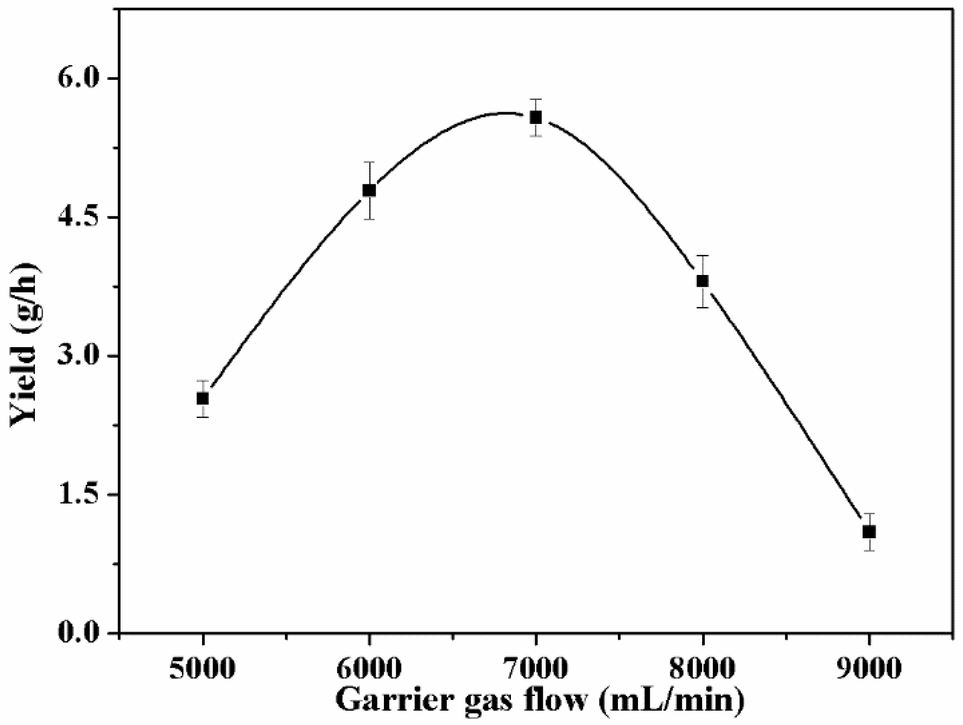
Figure 2 shows the yield of nanosized composite under different carrier gas (argon) flows with a certain flow of reaction gas (methane and silane). All the samples were collected under the same experimental conditions and tested by parallel experiments. When the mixture enters the plasma region under the carrier gas, it first breaks into many electriferous intermediates in the electric field, and these intermediates polymerize at the molecular scale and then nucleate and grow. Finally, the product is carried out of the plasma by the carrier gas. When the carrier gas flow is very low (<4000 mL/min), it is difficult to rotate the arc, resulting in high concentration of plasma and high temperature of the arc. Excessive temperature will cause the free radicals obtained by pyrolysis of silane and methane to reform into gaseous products instead of solid products. As the carrier gas flow increases, the arc starts to rotate, and the reaction gas/carrier gas ratio is more suitable for pyrolysis. The optimum carrier gas flow appears at 7000 mL/min. Under this condition, the maximum yield reaches 5.6 g/h. However, further increase of the carrier gas flow would lead to a decrease in yield. This is because a higher carrier gas flow shortens the residence time of methane or silane in the plasma [29]. Because of that, methane or silane cannot be pyrolyzed effectively. The experimental results in this work are consistent with previous studies [30].

3.2. Effect of Silane/Methane Ratio on Silicon-Carbon Nanocomposite

The Si nanoparticles act as a high energy store, and the carbon materials are expected to prevent the pulverization of the Si nanoparticles. Low silicon content will reduce the theoretical capacity of the composite, and low carbon content cannot restrain the volume changes of the silicon well. Therefore, the appropriate silicon-carbon ratio directly affects the electrochemical properties of the composite. Under the condition with a voltage of 8000 V, carrier gas flow of 6000 mL/min, and methane flow of 360 mL/min, the silicon-carbon nanocomposite was prepared with different silane and methane ratios. The ratio of silane to methane was 0:1, 1:10, 1:5, 1:3, 1:2, and 1:0, respectively, and the optimal ratio of silane to methane was determined to be 1:3.
Figure 3 shows the cycling stability of these six composites at a current of 150 mA g−1. It can be seen that the discharge capacity generally improves rapidly as the silane ratio increases, and then tends to decline. In terms of pure tremelliform carbon nanosheets, the specific capacity of the electrode is stabilized at 343 mAh g−1 after 50 cycles. With the addition of the silane, the specific capacity of the silicon-carbon nanocomposite increases significantly. As the ratio of silane to methane increases from 1:10 to 1:3, the specific capacity of the composite changes from 539 to 948 mAh g−1 after 50 cycles. However, when the ratio of silane to methane increases to 1:2, the discharge-specific capacity tends to decline. This may be because the amount of carbon materials is not sufficient to alleviate the volume change of the Si nanoparticles during the cycles, and the electrolyte decomposition repeatedly forms the SEI film on the Si nanoparticles surface during the cycles, which consumes a large amount of Li+ and leads to a decrease in the specific capacity (831 mAh g−1 after 50 cycles). A quick capacity fading is observed in the pure Si nanoparticles, which further suggests that the Si nanoparticles rapidly pulverize without the buffering effect of carbon materials. Above all, the optimal ratio of silane to methane is 1:3, and under this condition, the composite exhibits a higher stable specific capacity.

3.3. Effect of Hydrogen on Silicon-Carbon Nanocomposite

According to previous research, carbon black can be obtained by plasma pyrolysis of methane [31], while graphene can be further prepared by adding an appropriate ratio of hydrogen [32]. As for the effect of hydrogen, our research group has carried out in-depth research [32], through simulation, it was found that the addition of hydrogen can generate a large number of hydrogen atoms, which can form C-H bonds with carbon atoms on the edge of the carbon cluster, resulting in the decrease of carbon dangling bonds, and delaying the formation of spherical particles in the carbon cluster. Related studies have reported that the formed hydrogen atoms can react with the carbon cluster and form bonds, terminating the carbon-centered free radical to form sheet-like carbon materials [33]. On this basis, adding hydrogen is expected to prepare a new composite structure containing tremelliform carbon nanosheets, which could effectively buffer the volumetric changes of Si nanoparticles. Therefore, the influence of the hydrogen flow rate on the properties of the silicon-carbon nanocomposite was investigated under the conditions of a DC input voltage of 8000 V, a carrier gas flow of 6000 mL/min, silane flow rate of 120 mL/min, and methane flow rate of 360 mL/min.
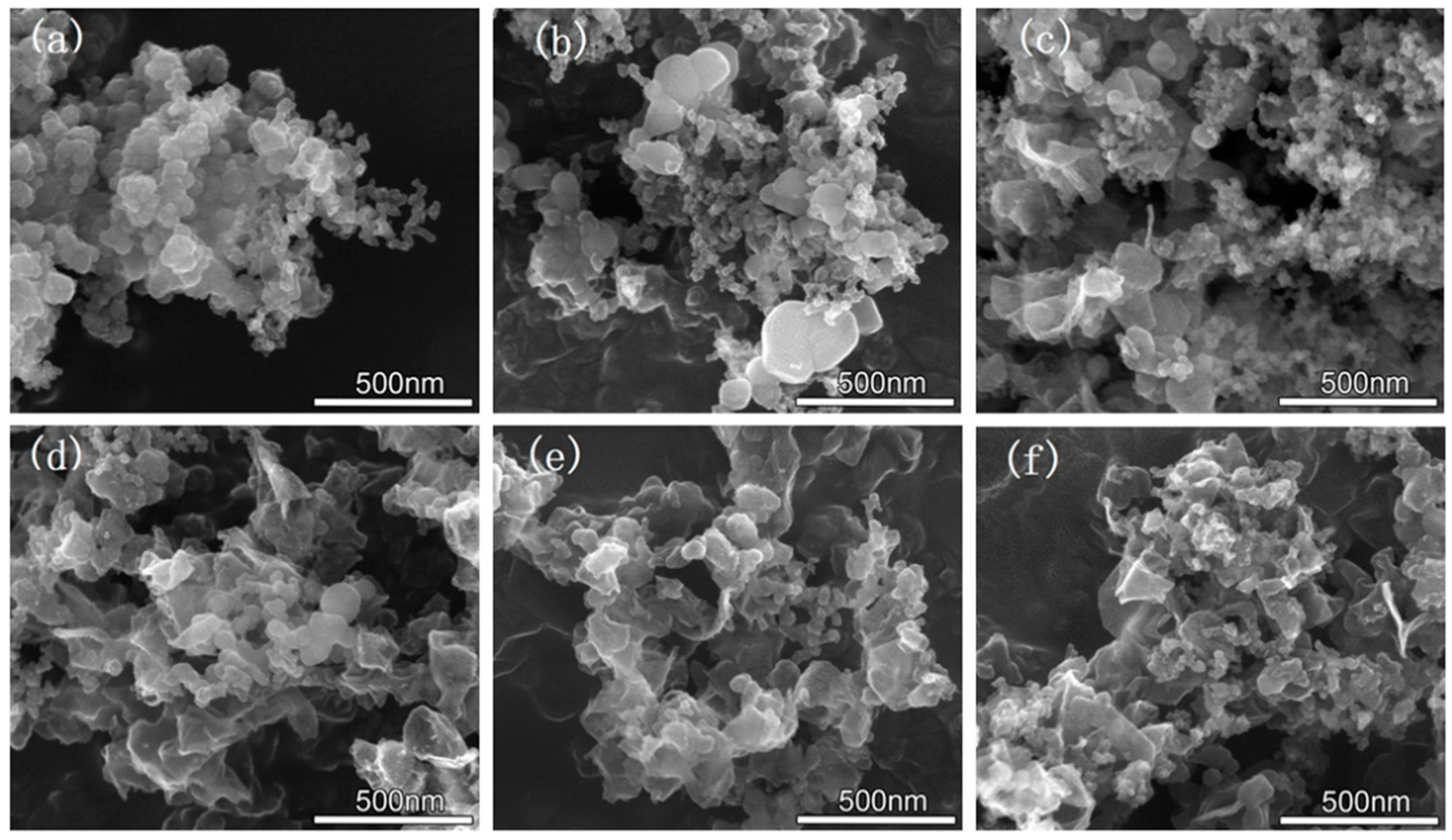
Figure 4 shows the SEM images of the composites prepared under the different rates of hydrogen to methane (0:1, 1:20, 1:10, 1:5, 1:3, and 1:2). As shown in Figure 4a, without the addition of hydrogen, the products are mainly spherical carbon and silicon nanoparticles with uneven dispersion. After the hydrogen is injected, the spherical carbon material becomes significantly larger and tends to tremelliform. Meanwhile, the Si nanoparticles and carbon materials are dispersed well (Figure 4b). When the ratio of hydrogen to methane increases, the proportion of the tremelliform carbon increases dramatically (Figure 4c,d). When the ratio of hydrogen to methane increases to 1:3 (Figure 4e), almost all of the carbon materials are tremelliform nanosheets, as the carbon changes from a spherical to a tremelliform nanosheet structure, the Si nanoparticles are dispersed much better among the tremelliform carbon nanosheets. The volume changes of Si nanoparticles can be effectively restrained by the tremelliform carbon nanosheets during the cycles. As the ratio of hydrogen to methane increases from 1:3 (Figure 4e) to 1:2 (Figure 4f), the structure of the composite remains basically unchanged. Because of that, the optimal ratio of hydrogen to methane is 1:3.

3.4. Characterization of the Silicon-Carbon Nanocomposite

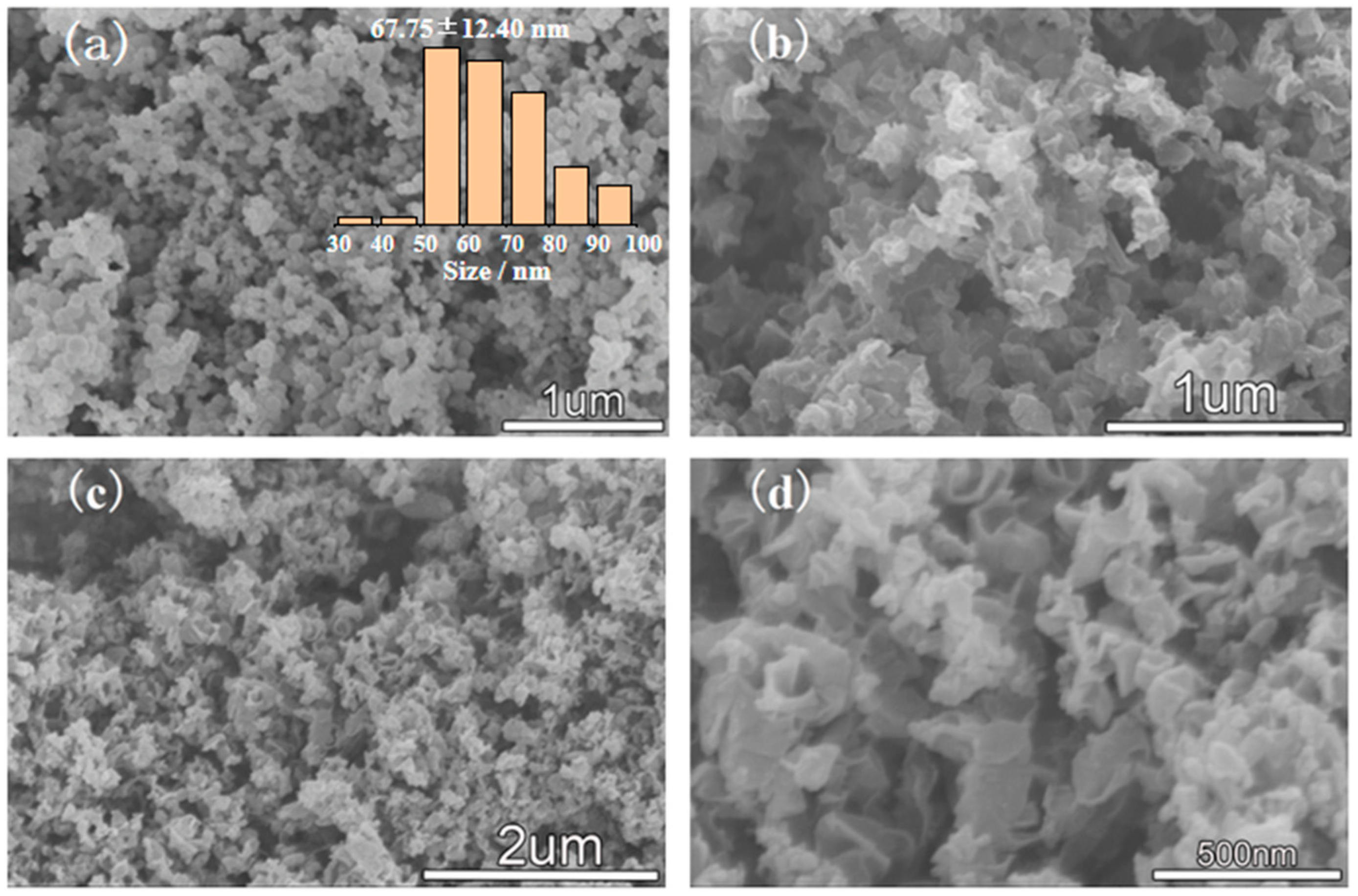
The detailed morphology, structure, and composition of the silicon-carbon nanocomposite prepared under the optimal conditions in this work were characterized. Figure 5 shows the SEM images of the different products prepared by the DC magnetoelectric plasma system. Figure 5a shows the spherical pure Si nanoparticles (size is in the range of 50–100 nm, under the ratio of hydrogen/silane of 1:1), the size distribution of the Si nanoparticles (inset) was obtained by analyzing the SEM image using SigmaScan software. Figure 5b shows the pure tremelliform carbon nanosheets (with a size of 200–400 nm, ratio of hydrogen/methane of 1:3). Figure 5c,d show the SEM images of the silicon-carbon nanocomposite prepared under the optimal condition (ratio of hydrogen/silane/methane of 1:1:3). It is obvious that the spherical Si nanoparticles are evenly dispersed among the tremelliform carbon nanosheets., which can effectively alleviate the agglomeration and volumetric change of Si nanoparticles during the cycles.
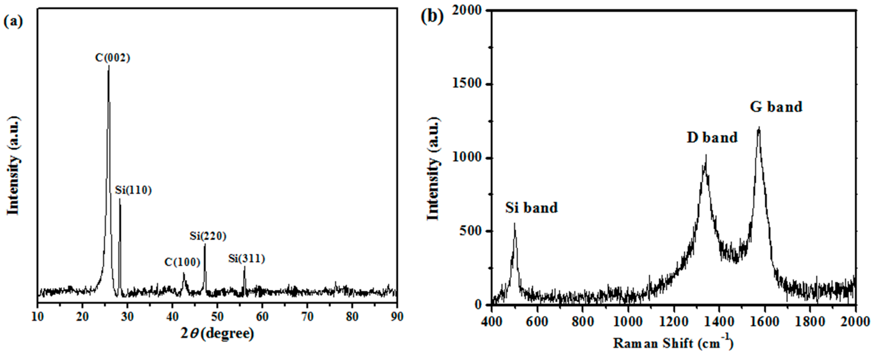
The XRD spectra of the silicon-carbon nanocomposite are shown in Figure 6a. The diffraction peaks at 28.4°, 47.3°, and 56.1° correspond to the (110), (220), and (311) crystal planes of Si nanoparticles, respectively [34,35,36,37]. Graphite (002) and (100) crystal planes were also found at 26.4° and 42.2°, which indicates that a part of carbon in the silicon-carbon nanocomposite was graphitized [38]. The diffraction peaks of SiC were not found in the spectra, indicating that the composite prepared by plasma was composed of only Si nanoparticles and tremelliform carbon nanosheets, and the silicon and carbon are physically bound together, which is completely consistent with the SEM image of the silicon-carbon nanocomposite (Figure 4). Figure 6b shows the Raman spectra of the silicon-carbon nanocomposite. A well-defined D band (1343 cm−1) is attributed to the amorphous structure of carbon, and the G band (1573 cm−1) associates with sp2-bonded corresponding to the graphitized carbon in the silicon-carbon nanocomposite [39]. The characteristic peak at 504 cm−1 corresponds to the crystalline Si. However, there is no typical peak of SiO2 (SiO2 has a asymmetric peak at 460 cm−1, a sharp peak at 490 cm−1, and two broad features peaks at 800 and 1050 cm−1) [40], further indicating that the silicon-carbon nanocomposite prepared by the plasma method is mainly composed of tremelliform carbon nanosheets and Si nanoparticles.

3.5. Electrochemical Performance of Silicon-Carbon Nanocomposite

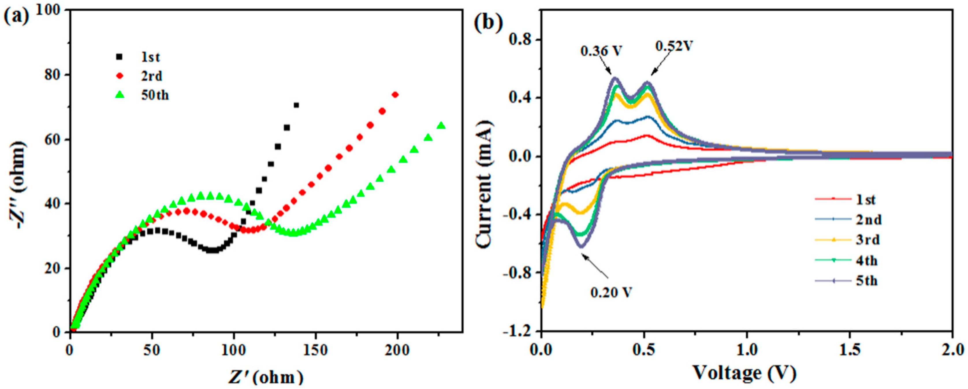
The electrochemical properties of the electrodes were measured by the EIS and CV measurements. Figure 7a shows the EIS of the electrodes after different cycles. The impedance spectrum consists of a semicircle, which is related to the charge-transfer impedance at the electrode-electrolyte interface in the high-frequency region, and a straight line, which implies the lithium diffusion impedance in the low frequency region. As the number of charge/discharge cycles increases, the diameter of the semicircle in the high-frequency region tends to increase. This is mainly due to the volume expansion of Si nanocomposite during the charge/discharge progress, which leads to the destruction of SEI film and the exposure of the Si nanocomposite surface. The formation of new SEI film consumes the electrolyte and thus increases the impedance. However, there is no significant difference among the three curves after 50 cycles. This indicates that the increase of interface impedance is limited during the cycles, and the SEI film formed is relatively stable [41], proving that the composite structure can efficiently alleviate the volumetric changes of Si nanocomposite.
Figure 7b shows the initial five CV curves of the composite. In the cathodic scan of the first cycle curve (discharge processes), a cathodic peak located at 0.1 V (vs. Li/Li+) is related to the LixSi (amorphous) alloy formation from Si (crystalline) and a phase transition from LixSi (amorphous) to Li15Si4 (crystalline); a broad reductive peak at about 0.25~0.9 V (vs. Li/Li+) corresponds to the decomposition reaction of electrolyte and the SEI film formation on the surface of the composite, which disappeared from the second cycle. Correspondingly, during the anodic scan (charge processes), the two anodic peaks at 0.36 and 0.52 V (vs. Li/Li+) are ascribed to the dealloying reactions from LixSi (amorphous) or Li15Si4 (crystalline) to Si (amorphous). From the second cycle, a cathodic peak at about 0.2 V and the two anodic peak (0.36 and 0.52 V) are characteristic of the phase transition between Li15Si4 (crystalline) and Si (amorphous) [42,43,44]. The increase in peak current is due to the continuous reaction of Si (crystalline) in the inner of the nanoparticles with Li during the repeated lithiation/delithiation [45,46]. The conclusion seems reasonable that the Si nanocomposite is the main reactant with Li and the main provider of Li storage capacity in the silicon-carbon nanocomposite.
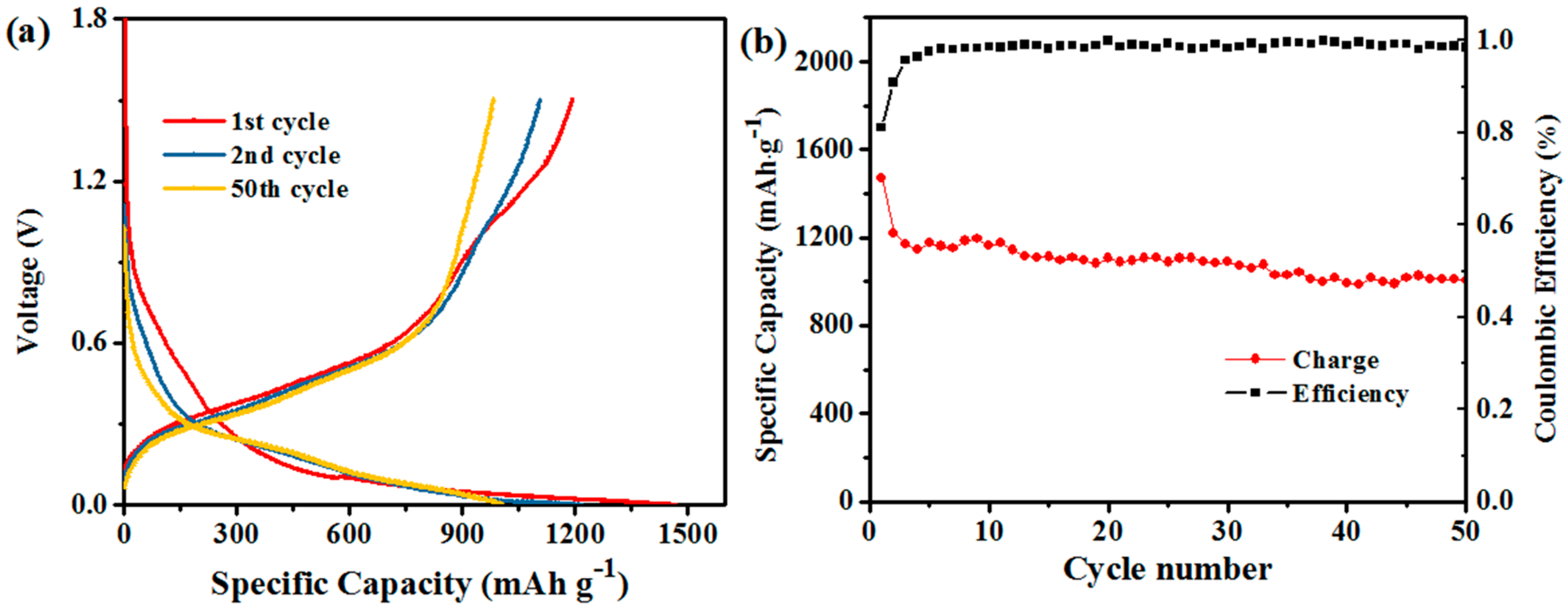
Figure 8a displays the charge/discharge profiles of the silicon-carbon nanocomposite for 1st, 2nd, and 50th cycle, respectively. The galvanostatic cycling was carried out at a current density of 150 mA g−1. The initial discharge and charge capacities of the silicon-carbon nanocomposite are 1469 and 1193 mAh g−1, respectively, and the coulombic efficiency of the first cycle is 81.2%. The initial irreversible capacity is mainly due to the SEI film formation on the composite, and the irreversible process disappeared during the subsequent cycles. For the second cycle, the discharge and charge capacities of the electrode are 1217 and 1106 mAh g−1, respectively, and the coulombic efficiency increases to 90.8%. After the second cycle, the coulombic efficiency rapidly reaches 99% and remains stable for 50 cycles. After 50 cycles, the discharge-specific capacity of the composite electrode is 1007 mAh g−1 with a high capacity retention of 68.6 % as shown in Figure 8b, and the good cycling stability attributed to the silicon-carbon nanocomposite structure effectively alleviates the volumetric expansion during the cycles.
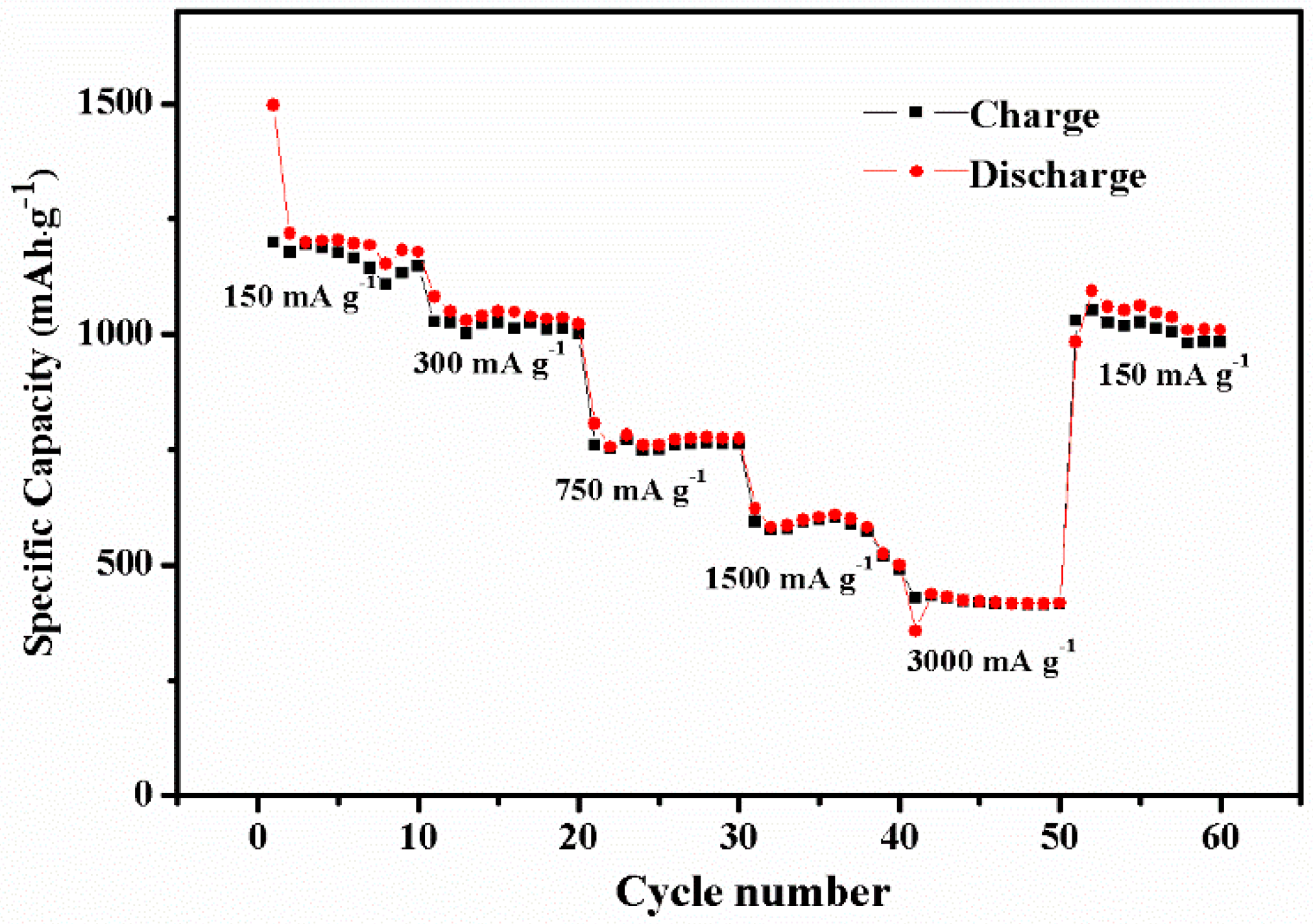
Figure 9 shows the rate performance of the silicon-carbon nanocomposite at different current densities from 150 to 3000 mA g−1. It can be seen that the silicon-carbon nanocomposite delivered the reversible capacities of 1118, 1035, 775, 600, and 414 mAh g−1 at the current densities of 150, 300, 750, 1500, and 3000 mA g−1, respectively. The reversible capacity quickly restores to 1010 mAh g−1, when the current density drops to 150 mA g−1, indicating the silicon-carbon composite has a good rate performance.

4. Conclusions

In summary, the silicon-carbon nanocomposite was facilely synthesized by the one-step magnetoelectric plasma pyrolysis method. The effects of the ratio of silane, methane, and hydrogen on the properties of the composites were investigated in this paper. Under the optimized ratio of hydrogen/silane/methane (1:1:3), the silicon-carbon nanocomposite is composed of tremelliform carbon nanosheets and spherical Si nanoparticles and without SiO2 and SiC according to the XRD and Raman spectroscopy analysis. As anodes for LIBs, the tremelliform carbon nanosheets of silicon-carbon nanocomposite can efficiently alleviate the volume changes of Si nanoparticles during the cycles. The initial specific capacity of the silicon-carbon composite is 1469 mAh g−1 at a current density of 150 mA g−1 with a coulombic efficiency of 68.3%, and the reversible capacity is stable at 1007 mAh g−1 after 50 cycles. Furthermore, in the rate performance test, when the current density returned from 3000 to 150 mA g−1, the specific capacity increased rapidly from 400 to 1010 mAh g−1. The good specific capacity, cycling stability, and rate performance may be attributed to the efficient structure of the silicon-carbon nanocomposite.

Author Contributions

Conceptualization, R.H.; Data Curation, M.G.; Formal Analysis, F.W.; Funding Acquisition, R.H.; Investigation, F.W.; Methodology, F.W.; Project Administration, R.H.; Software, M.G.; Supervision, R.H.; Validation, R.H.; Visualization, M.G.; Writing–Original Draft, F.W.; Writing–Review & Editing, X.L. All authors have read and agreed to the published version of the manuscript.

Funding

This research was financially supported by the National Natural Science Foundation of China (NSFC, No. 21246002), Minjiang Scholarship of Fujian Province (No. Min-Gaojiao[2010]-117), Central-government Guided Fund for Local Economic Development (No. 830170778), R&D Fund for Strategic Emerging Industry of Fujian Province (No. 82918001), and International Cooperation Project of Fujian Science and Technology Department (No. 830170771).

Conflicts of Interest

The authors declare no conflict of interest.

References

  1. Choi, J.W.; Aurbach, D. Promise and reality of post-lithium-ion batteries with high energy densities. Nat. Rev. Mater. 2016, 1, 1–13. [Google Scholar] [CrossRef]
  2. Bruce, P.; Scrosati, B.; Tarascon, J.M. Nanomaterials for rechargeable lithium batteries. Angew. Chem. Int. Ed. 2008, 47, 2930–2946. [Google Scholar] [CrossRef] [PubMed]
  3. Dunn, B.; Kamath, H.; Tarascon, J.M. Electrical Energy Storage for the Grid: A Battery of Choices. Science 2011, 334, 928–935. [Google Scholar] [CrossRef] [PubMed] [Green Version]
  4. Winter, M.; Jürgen, O.B.; Spahr, M.E.; Novak, P. Insertion electrode materials for rechargeable lithium batteries. Adv. Mater. 1998, 10, 725–763. [Google Scholar] [CrossRef]
  5. Endo, M.; Kim, C.; Nishimura, K.; Fujino, T.; Miyashita, K. Recent Development of Carbon Materials for Li Ion Batteries. Carbon 2000, 38, 183–197. [Google Scholar] [CrossRef]
  6. Zhou, M.; Liu, Y.; Chen, J.; Yang, X.; Mater, J. Double shelled hollow SnO2/polymer microsphere as a high-capacity anode material for superior reversible lithium ion storage. J. Mater. Chem. A 2015, 3, 1068–1076. [Google Scholar] [CrossRef]
  7. Zhu., Z.; Wang, S.; Du, J.; Jin, Q.; Zhang, T.; Cheng, F. Ultrasmall sn nanoparticles embedded in nitrogen-doped porous carbon as high-performance anode for lithium-ion batteries. Nano Lett. 2014, 14, 153–157. [Google Scholar] [CrossRef]
  8. Huang, X.; Yang, J.; Mao, S.; Chang, J.; Hallac, P.B.; Fell, C.R.; Metz, B.; Jiang, J.; Hurley, P.T.; Chen, J. Controllable synthesis of hollow Si anode for long-cycle-life lithium-ion batteries. Adv. Mater. 2014, 26, 4326–4332. [Google Scholar] [CrossRef]
  9. Zhou, X.; Guo, Y.G. A peo-assisted electrospun silicon-graphene composite as an anode material for lithium-ion batteries. J. Mater. Chem. A 2013, 1, 9019–9023. [Google Scholar] [CrossRef]
  10. Yang, X.Y.; Tachikawa, N.; Katayama, Y.; Li, L.; Yan, J.W. Effect of the pillar size on the electrochemical performance of laser-induced silicon micropillars as anodes for lithium-ion batteries. Appl. Sci. 2019, 9, 3623. [Google Scholar] [CrossRef] [Green Version]
  11. Poizot, P.; Laruelle, S.; Grugeon, S.; Dupont, L.; Tarascon, J.M. Nano-sized transition-metal oxides as negative-electrode materials for lithium-ion batteries. Nature 2000, 407, 496–499. [Google Scholar] [CrossRef] [PubMed]
  12. Peng, L.; Zhang, H.J.; Bai, Y.J.; Zhang, Y.; Wang, Y. A self-supported peapod-like mesoporous TiO2-C array with excellent anode performance in lithium-ion batteries. Nanoscale 2015, 7, 8758–8765. [Google Scholar] [CrossRef]
  13. Wang, B.; Li, X.; Zhang, X.; Luo, B.; Jin, M.; Liang, M.; Dayeh, S.A.; Picraux, S.T.; Zhi, L. Adaptable silicon-carbon nanocables sandwiched between reduced graphene oxide sheets as lithium ion battery anodes. Acs Nano 2013, 7, 1437–1445. [Google Scholar] [CrossRef] [PubMed]
  14. Jia, H.P.; Zheng, J.M.; Song, J.K.; Luo, L.L.; Zhang, J.-G. A novel approach to synthesize micrometer-sized porous silicon as a high performance anode for lithium-ion batteries. Nano Energy 2018, 50, 589–597. [Google Scholar] [CrossRef]
  15. Yu, Y.; Gu, L.; Zhu, C.; Tsukimoto, S.; van Aken, P.A.; Maier, J. Reversible storage of lithium in silver-coated three-dimensional macroporous silicon. Adv. Mater. 2010, 22, 2247–2250. [Google Scholar] [CrossRef] [PubMed]
  16. Li, H.; Lu, C.; Zhang, B. A straightforward approach towards Si@C/graphene nanocomposite and its superior lithium storage performance. Electrochim. Acta 2014, 120, 96–101. [Google Scholar] [CrossRef]
  17. Feng, K.; Li, M.; Liu, W.W.; Kashkooli, A.G.; Chen, Z.W. Silicon-based anodes for lithium-ion batteries: From fundamentals to practical applications. Small 2018, 14, 1702737–1702769. [Google Scholar] [CrossRef]
  18. Liu, X.; Du, Y.; Hu, L.; Zhou, X.; Li, Y.; Dai, Z.; Bao, J. Understanding the effect of different polymeric surfactants on enhancing the silicon/reduced graphene oxide anode performance. J. Phys. Chem. C 2015, 119, 5848–5854. [Google Scholar] [CrossRef]
  19. Kim, J.; Yang, S.Y.; Kim, K.Y. Improving the microstructure and electrochemical performance of carbon nano-fibers containing graphene-wrapped silicon nanoparticles as a li-ion battery anode. J. Power Sources 2015, 273, 404–412. [Google Scholar] [CrossRef]
  20. Park, M.S.; Park, E.; Lee, J.; Jeong, G.; Kim, K.J.; Kim, J.H.; Kim, Y.J.; Kim, H. Hydrogen silsequioxane-derived Si/SiOx nano-spheres for high-capacity lithium storage materials. Acs Appl. Mater. Inter. 2014, 6, 9608–9613. [Google Scholar] [CrossRef]
  21. Kim, S.Y.; Kim, B.H.; Yang, K.Y. Preparation and electrochemical characteristics of a polyvinyl pyrrolidone-Stabilized Si/carbon composite nanofiber anode for a lithium ion battery. J. Electroanal. Chem. 2013, 705, 52–56. [Google Scholar] [CrossRef]
  22. Liu, N.; Wu, H.; McDowell, M.T.; Yao, Y.; Wang, C.; Cui, Y. A yolk-shell design for stabilized and scalable li-ion battery alloy anodes. Nano Lett. 2012, 12, 3315–3321. [Google Scholar] [CrossRef] [PubMed] [Green Version]
  23. Pan, L.; Wang, H.; Gao, D.; Chen, S.; Tan, L.; Li, L. Facile synthesis of yolk-shell structured Si-C nanocomposites as anodes for lithium-ion batteries. Chem. Commun. 2014, 50, 5878–5880. [Google Scholar] [CrossRef] [Green Version]
  24. Ng, S.H.; Wang, J.; Wexler, D.; Konstantinov, K.; Guo, Z.P.; Liu, H.K. Highly reversible lithium storage in spheroidal carbon-coated silicon nanocomposites as anodes for lithium-ion batteries. Angew. Chem. Int. Ed. 2006, 45, 6896–6899. [Google Scholar] [CrossRef] [PubMed]
  25. Kim, S.Y.; Lee, J.; Kim, B.H.; Kim, Y.J.; Yang, K.S.; Park, M. A facile synthesis of carbon-coated silicon/graphite spherical composites for high-performance lithium-ion Batteries. Acs Appl. Mater. Inter. 2016, 8, 12109–12117. [Google Scholar] [CrossRef]
  26. Wang, L.Y.; Liu, Z.J.; Guo, Q.G.; Guo, X.H.; Gu, J.J. Electrochemical properties of a silicon nanoparticle/hollow graphite fiber/carbon coating composite as an anode for lithium-ion batteries. Rsc Adv. 2017, 7, 36735–36743. [Google Scholar] [CrossRef] [Green Version]
  27. Saint, J.; Morcrette, M.; Larcher, D.; Laffont, L.; Beattie, S.; Pérès, J.P.; Talaga, D.; Couzi, M.; Tarascon, J.M. Towards a fundamental understanding of the improved electrochemical performance of silicon-carbon composites. Adv. Funct. Mater. 2007, 17, 1765–1774. [Google Scholar] [CrossRef]
  28. Ng, S.H.; Wang, J.; Wexler, D.; Chew, S.Y.; Liu, H.K. Amorphous carbon-coated silicon nanocomposites: A low-temperature synthesis via spray pyrolysis and their application as high-capacity anodes for lithium-ion batteries. J. Phys. Chem. C 2007, 111, 11131–11138. [Google Scholar] [CrossRef] [Green Version]
  29. Wang, F.; Hong, R.Y. Continuous preparation of structure-controlled carbon nanoparticle via arc plasma and the reinforcement of polymeric composites. Chem. Eng. J. 2017, 328, 1098–1111. [Google Scholar] [CrossRef]
  30. Park, J.; Heberlein, J.; Pfender, E.; Candler, G.; Chang, C.H. Two-dimensional numerical modeling of direct-current electric arcs in nonequilibrium. Plasma Chem. PlasmaP. 2008, 28, 213–231. [Google Scholar] [CrossRef]
  31. Wang, F.; Sun, D.L.; Hong, R.Y.; Kumar, M.R. Preparation of carbon nanoparticles by plasma arc discharge under fluidized dynamic equilibrium. J. Nanopart. Res. 2006, 18, 148–162. [Google Scholar] [CrossRef]
  32. Zhong, R.P.; Hong, R.Y. Continuous preparation and formation mechanism of few-layer graphene by gliding arc plasma. Chem. Eng. J. 2020, 387, 124102–124111. [Google Scholar] [CrossRef]
  33. Li, B.; Nan, Y.L.; Cao, H.; Yan, P.; Zhao, S.R.; Zhao, X.; Song, X.L. Arc plasma-assisted hydrogenation of few-layer graphene in methane hydrogen atmospheres. Diam. Relat. Mater. 2017, 76, 44–49. [Google Scholar] [CrossRef]
  34. Doğan, İ.; Weeks, S.L.; Agarwal, S.; van de Sanden, M.C.M. Nucleation of silicon nanocrystals in a remote plasma without subsequent coagulation. J. Appl. Phys. 2014, 115, 244301–244309. [Google Scholar] [CrossRef] [Green Version]
  35. Seo, M.H.; Park, M.; Lee, K.T.; Kim, K.; Kim, J.; Cho, J. High performance Ge nanowire anode sheathed with carbon for lithium rechargeable batteries. Energ. Environ. Sci. 2011, 4, 425–428. [Google Scholar] [CrossRef] [Green Version]
  36. Lee, J.I.; Choi, N.S.; Park, S. Highly stable Si-based multicomponent anodes for practical use in lithium-ion batteries. Energ. Environ. Sci. 2012, 5, 7878–7882. [Google Scholar] [CrossRef] [Green Version]
  37. Li, Z.; Huang, J.J.; Zhang, Z.Z.; Zhao, F.X.; Wu, Y. Preparation of high purity nano-silicon powders by direct current arc plasma evaporation method. Mater. Sci. Eng. B 2018, 229, 6–12. [Google Scholar] [CrossRef]
  38. Lu, S.; Blanco, C.; Appleyard, S.; Hammond, C.; Rand, B. Texture studies of carbon and graphite tapes by XRD texture goniometry. J. Mater. Sci. 2002, 37, 5283–5290. [Google Scholar] [CrossRef]
  39. Yin, L.; Wang, J.; Lin, F.; Yang, J.; Nuli, Y. Polyacrylonitrile/graphene composite as a precursor to a sulfur-based cathode material for high-rate rechargeable Li-S batteries. Energ. Environ. Sci. 2012, 5, 6966–6972. [Google Scholar] [CrossRef]
  40. Li, B.; Yu, D.; Zhang, S.L. Raman spectral study of silicon nanowires. Phys. Rev. B 1999, 59, 1645–1648. [Google Scholar] [CrossRef]
  41. Guo, J.C.; Sun, A.; Chen, X.L.; Wang, C.S.; Manivannan, A. Cyclability study of silicon-carbon composite anodes for lithium-ion batteries using electrochemical impedance spectroscopy. Electrochim. Acta 2011, 56, 3981–3987. [Google Scholar] [CrossRef]
  42. Hu, R.Z.; Sun, W.; Liu, H.; Zeng, M.; Zhu, M. The fast filling of nano-SnO2 in CNTs by vacuum absorption: A new approach to realize cyclic durable anodes for lithium ion batteries. Nanoscale 2013, 5, 11971–11979. [Google Scholar] [CrossRef] [PubMed]
  43. Hassoun, J.; Lee, K.S.; Sun, Y.K.; Scrosati, B. An advanced lithium ion battery based on high performance electrode materials. J. Am. Chem. Soc. 2011, 133, 3139–3143. [Google Scholar] [CrossRef]
  44. Sun, W.; Hu, R.Z.; Zhang, H.Y.; Wang, Y.K.; Yang, L.C.; Liu, J.W.; Zhu, M. A long-life nano-silicon anode for lithium ion batteries: Supporting of graphene nanosheets exfoliated from expanded graphite by plasma-assisted milling. Electrochim. Acta 2016, 187, 1–10. [Google Scholar] [CrossRef]
  45. Wu, J.X.; Qin, X.Y.; Zhang, H.R.; He, Y.B.; Li, B.H.; Ke, L.; Lv, W.; Du, H.D.; Yang, Q.H.; Kang, F.Y. Multilayered silicon embedded porous carbon/graphene hybrid film as a high performance anode. Carbon 2015, 84, 434–443. [Google Scholar] [CrossRef]
  46. Zhang, Y.Y.; Li, K.; Ji, P.Y.; Chen, D.Q.; Zeng, J.; Sun, Y.Z.; Zhang, P.; Zhao, J.B. Silicon-multi-walled carbon nanotubes-carbon microspherical composite as high-performance anode for lithium-ion batteries. J. Mater. Sci. 2016, 52, 1–12. [Google Scholar] [CrossRef]
Figure 1. DC magnetoelectric plasma installation. (a) Schematic diagram, (b) Discharge device.
Applsci 10 02672 g001
Figure 2. Yield of solid products under different carrier gas flows.
Applsci 10 02672 g002
Figure 3. Cyclic performance of the silicon-carbon nanocomposite prepared under different silane/methane ratios at 150 mA g−1 between 0.01 and 1.5 V.
Applsci 10 02672 g003
Figure 4. SEM images of the silicon-carbon nanocomposite prepared with different hydrogen/methane ratios. (a) No hydrogen, (b) 1:20, (c) 1:10, (d) 1:5, (e) 1:3, (f) 1:2.
Applsci 10 02672 g004
Figure 5. SEM images of the pure Si nanoparticles (a), pure tremelliform carbon nanosheets (b), silicon-carbon nanocomposite (c,d) prepared by DC magnetoelectric plasma under optimal conditions. Inset: size distribution of the Si nanoparticles.
Applsci 10 02672 g005
Figure 6. XRD pattern (a) and Raman pattern (b) of the silicon-carbon nanocomposite prepared by DC magnetoelectric plasma under optimal conditions.
Applsci 10 02672 g006
Figure 7. (a) Electrochemical impedance spectroscopy (EIS) of the silicon-carbon nanocomposite after different cycles, (b) cyclic voltammetry (CV) curves of the silicon-carbon nanocomposite from 0.01 to 2.0 V at a scanning rate of 0.1 mV s−1.
Applsci 10 02672 g007
Figure 8. Charge/discharge profiles (a) and cycling performance (b) of the silicon-carbon nanocomposite at 150 mA g−1 between 0.01 and 1.5 V.
Applsci 10 02672 g008
Figure 9. Rate capability of the silicon-carbon nanocomposite at different current densities between 0.01 and 1.5 V.
Applsci 10 02672 g009