3.1. Oscillation Characteristics of Weld Pool in P-GMAW
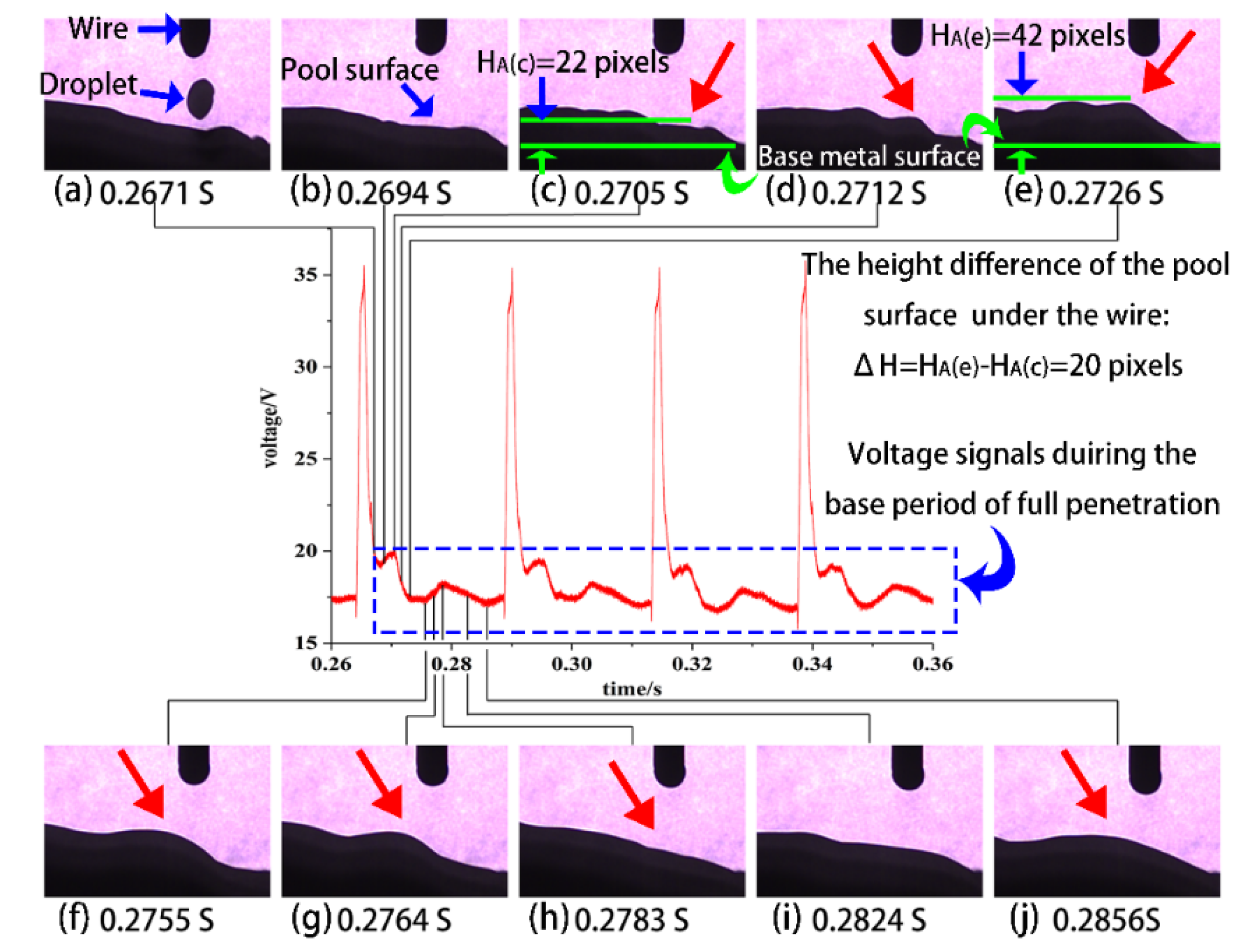
P-GMAW has the advantages of directional metal transfer and no spatter over wide ranges of heat and mass input levels. It uses a low base current to maintain the arc and a high peak current to melt the electrode wire and detach the droplet. The impact force of the droplet was the main factor to trigger the oscillation behavior of the weld pool.
Figure 4 and
Figure 5 show the dynamic behavior of the weld pool during base current under full and partial penetration.
Figure 4 and
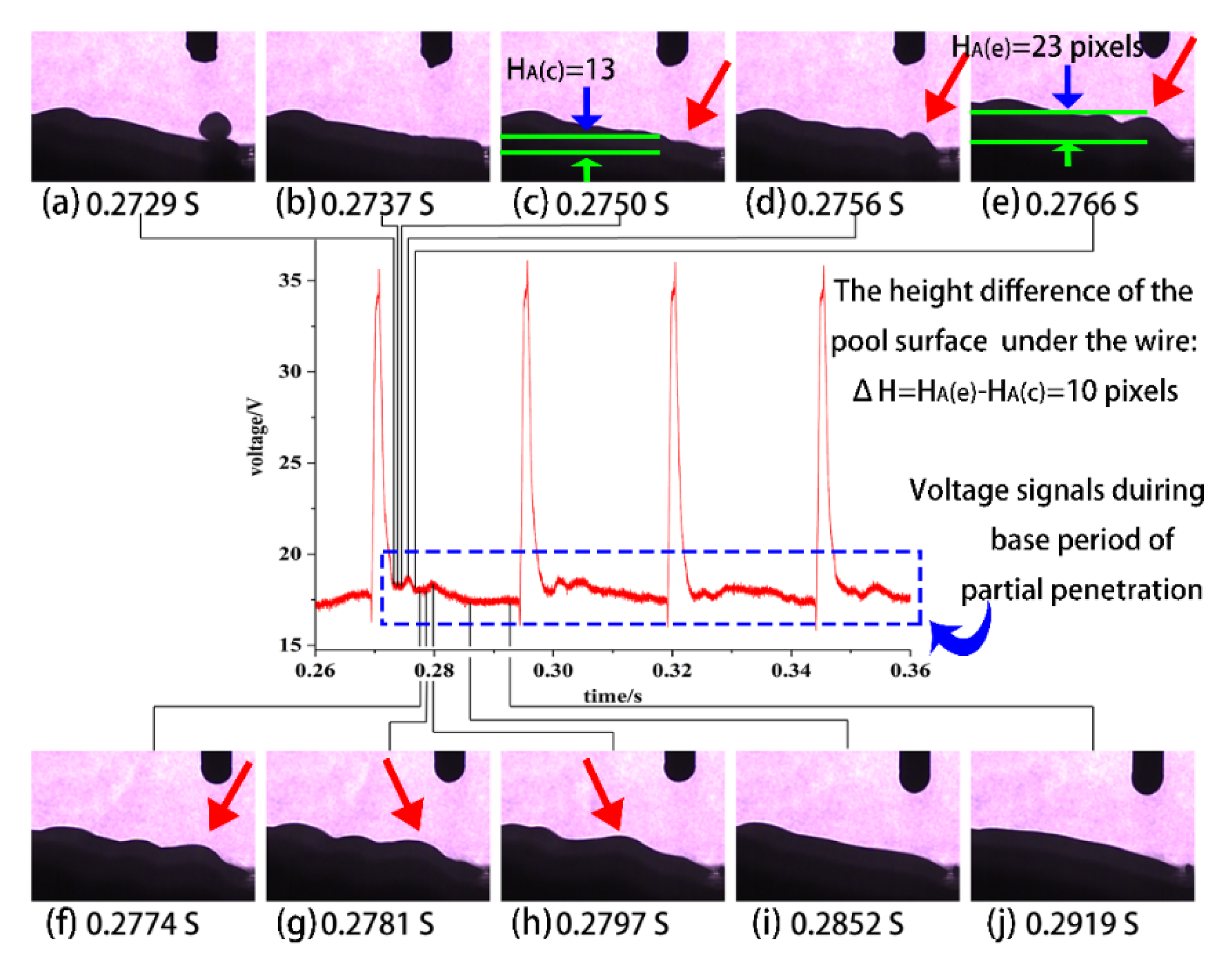
Figure 5 show that the weld pool surface below the wire was depressed due to the impact of the droplet, then the surface of the weld pool bounces to form waves. The red arrow of
Figure 4 and
Figure 5 show the positions of wave peaks on the weld pool surface at different times. Under the same pulse parameters, the impacts of the droplets on the pool were similar [
15], while the fully penetrated weld pool and the partly penetrated weld pool have a distinct difference in the oscillation behavior. Compared with the oscillation amplitude of the partial penetrated pool (according to the ΔH = 20 pixels in
Figure 4), the oscillation amplitude of the fully penetrated weld pool was larger (according to the ΔH = 10 pixels in
Figure 5). The difference in the oscillation behavior of the weld pool leads to the difference in the arc length, which resulted the difference from the voltage signals (as shown from the blue boxes in
Figure 4 and
Figure 5).
To further study the relationship between penetration status and oscillation behavior of the weld pool, the welding joints with different penetration status were manufactured under different welding travel speeds with the same welding parameters. Analysis of the weld pool dynamics was carried out by measuring the Y-coordinate of the reference point A on the pool surface with time, as described in
Section 2.1. The results of the analysis for weld pools with different penetration status are presented in
Figure 6a–g respectively.
The start time in
Figure 6 is the moment at the droplet entered the pool completely. The test was repeated 3–4 times to verify the repeatability of the weld pool oscillation behavior for each parameter. The weld pool was agitated, and waves were generated due to the impact of the droplets after the droplet impacts the weld pool. In this paper, the first wave peak was called the initial wave peak, the amplitude of each curve was measured in this paper, as shown in
Figure 6a. The energy of which was derived from the momentum carried by the droplet. After the liquid surface falls back, the amplitude of the subsequent wave peak was smaller than that of the first wave peak due to the energy loss of the oscillation [
11]. The weld pool penetration gradually changed from full penetration to critical penetration with the welding speed increased, and the amplitude of the wave peak decreased gradually while the number of subsequent wave peak increased, as shown in
Figure 6a–d. However, only one wave peak occurred on the curves for the partly penetrated weld pools, as shown in
Figure 6e–g. In this paper, all weld joints were manufactured under the same parameters, welding speed was the only variable parameters, so the impact force applied to all weld pools were consistent. The geometry and boundary conditions of the weld pool under different penetration status were the main factors causing different motion behaviors.
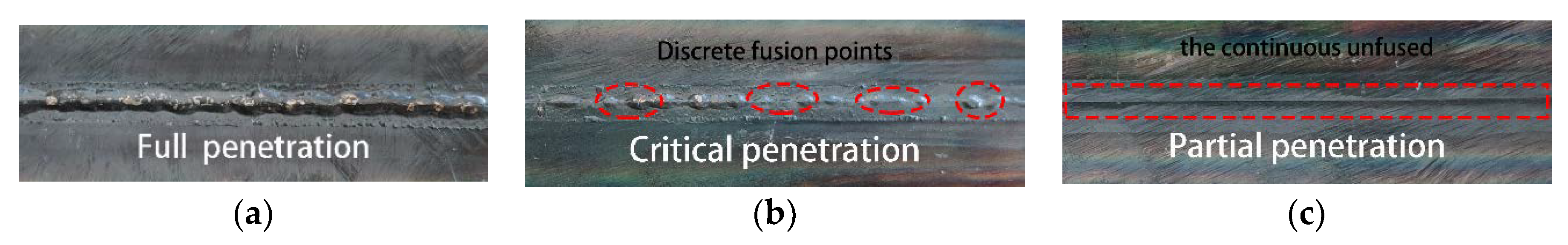
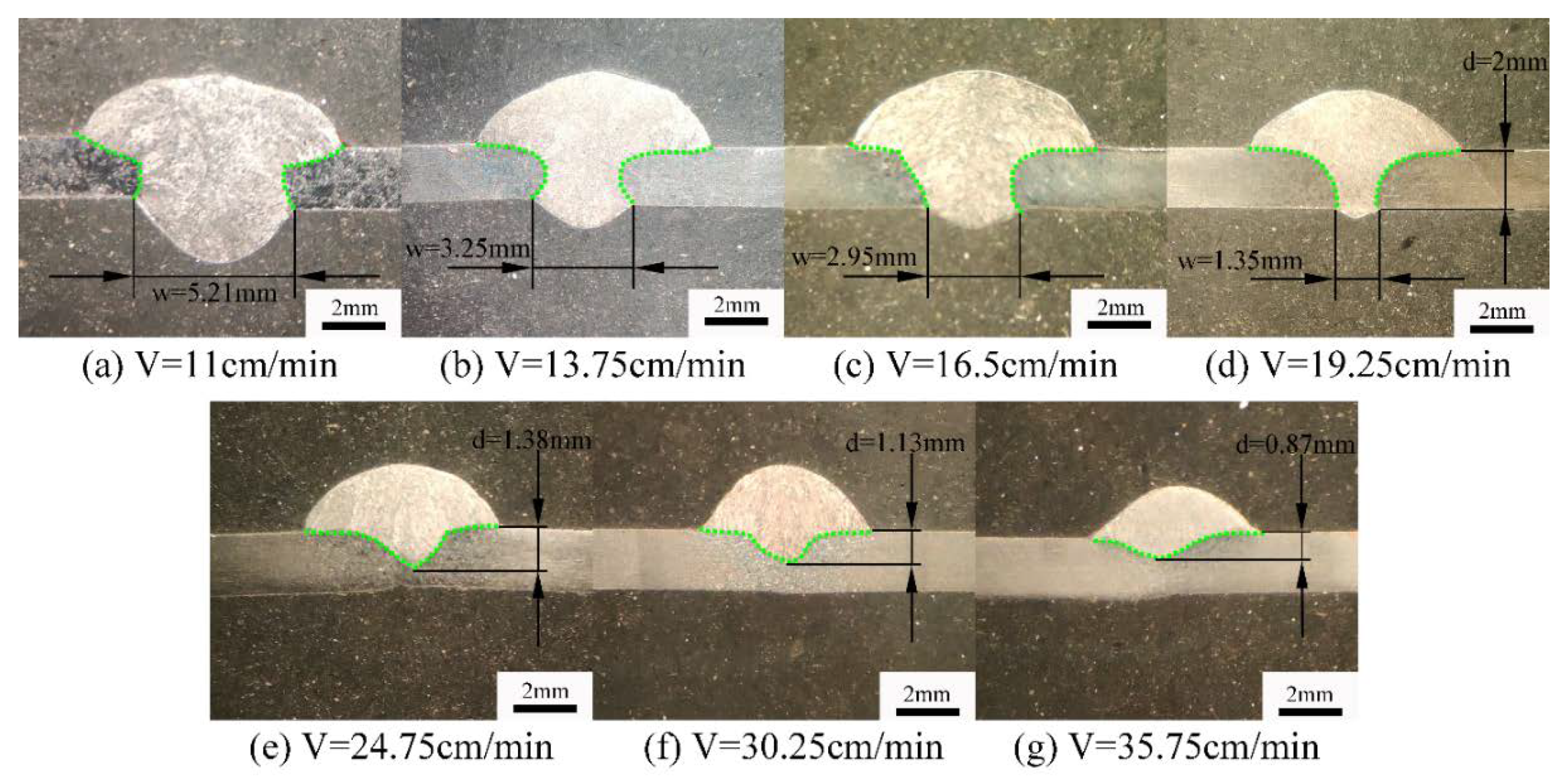
Figure 7 shows the geometry of the weld joints under different penetration status, and the effective throat thickness and the width of the back weld were calibrated according to ISO-17695.
As shown in
Figure 7, the cross-sectional area and penetration depth of the weld decreased with the acceleration of the welding speed. As for full penetration status, the effective thickness (d) of the weld was 2 mm, and the width of the back weld (w) decreases with the increase of the welding speed as shown in
Figure 7a–c. The effective thickness of the critical penetration was 2 mm, and the width of the back weld (w) was 1.35 mm as shown in
Figure 7d. As for partial penetration. Effective weld thickness (d) decreased with the increase of welding speed, as shown in
Figure 7e–g.
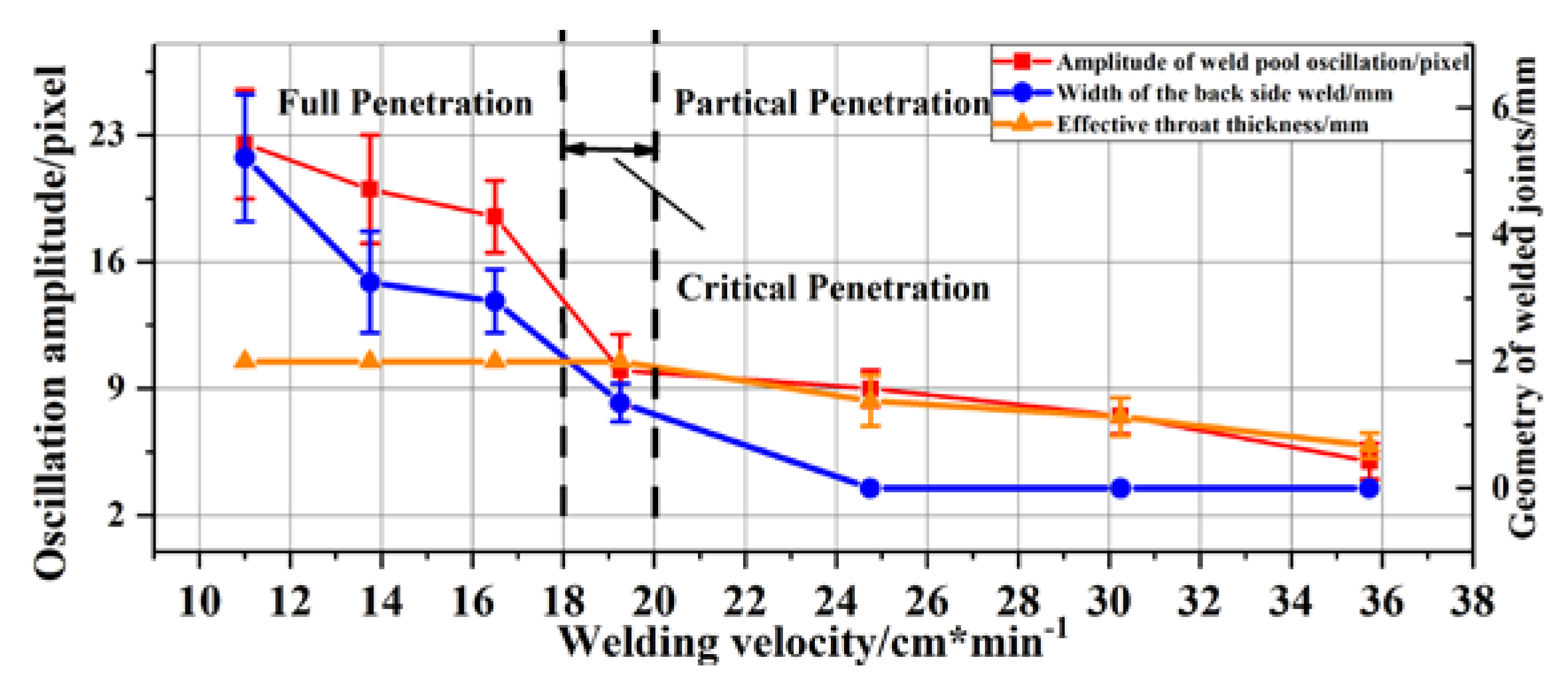
Figure 8 shows the amplitude of the initial oscillation peak and the geometry of the weld joints under different penetration status.
Figure 8 shows the curves of oscillation amplitude and the geometry of weld joints with different welding speeds. The oscillation amplitude decreased with increasing welding speed and an abrupt change occurred in the amplitude of weld pool oscillation with the transition from full to partial penetration status. Different boundary conditions between partly and fully penetrated weld pool led to different oscillation modes and amplitude.
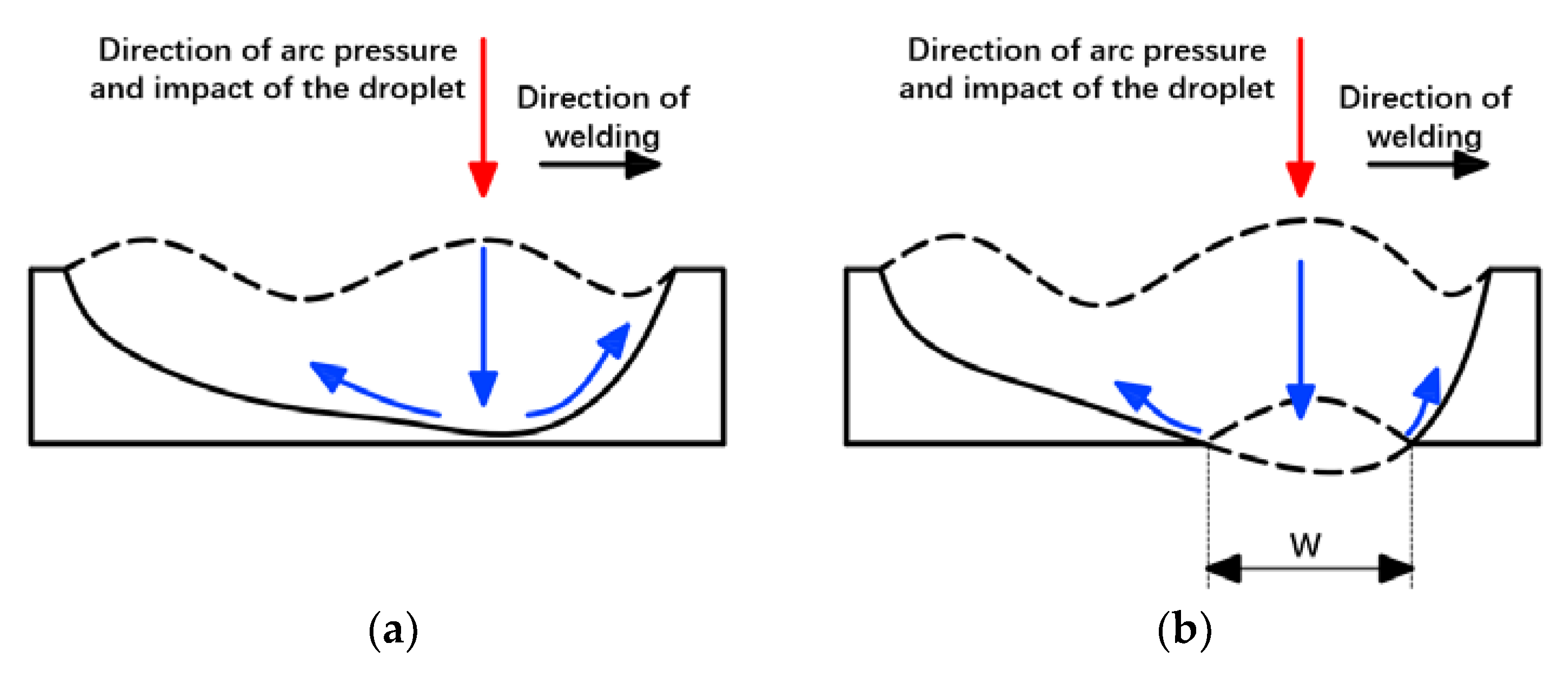
Figure 9 shows the oscillation mode with different penetration status. For partly penetrated weld pool, the bottom of the weld pool was supported by the solid material, which obstructed the downward movement of the molten metal. It led to a greater loss of energy in the process of oscillation, resulting in a lower amplitude. As for critical penetration status, the main part of the pool was supported by the solid metal with relatively small W, leading to the similar oscillation behavior as the partial penetration, as shown in
Figure 6d,e. As for full penetration, W was relatively larger. The weld pool was only supported by the surface tension of the molten metal within the range of W. In this case, a new free surface and degree of freedom were generated in the weld pool, which led to a change in the oscillation mode of the weld pool. Zacksenhouse and Hardt established an analytical model based on the theory of stretch membrane and studied the oscillatory behavior of the fully penetrated pool [
16]. It was found that the oscillation amplitude of the stationary full penetration pool was more intense than that of the partial and critical penetration due to the lack of solid boundary constraint at the weld pool bottom.
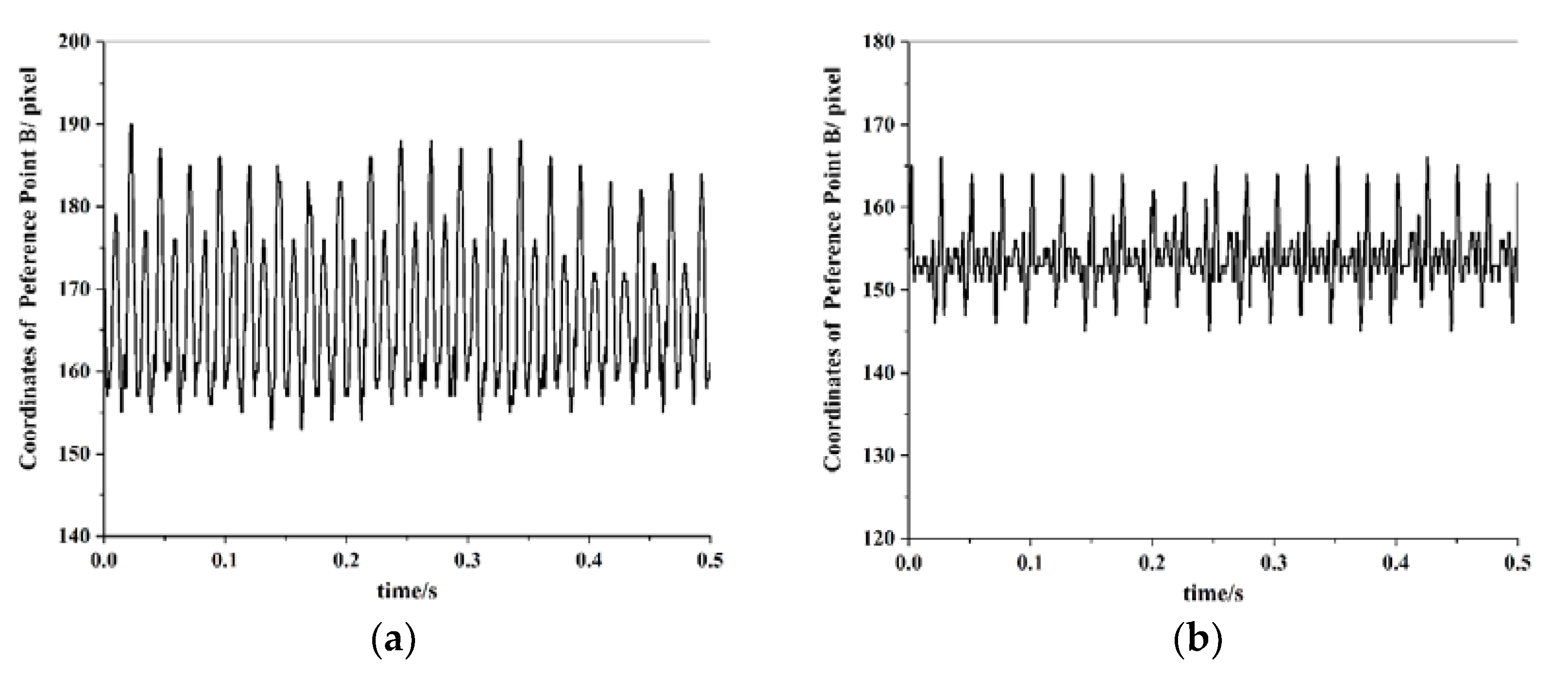
The change of oscillation mode leads to the different oscillation frequency characteristics of the weld pool. The location information of reference point A cannot be continuously extracted because the droplet impinged on the weld pool there. In this experiment, the measured height of reference point B (H
B) for partial and full penetration status are plotted as a function of time in
Figure 10.
The oscillation signal of the weld pool was a nonlinear time-varying signal. The Continuous Wavelet Transform (CWT) can analyze time-varying signals in the time domain and frequency domain simultaneously. In this paper, Morlet wavelet was used as the square-integrable function of CWT, also known as the wavelet basis function, as shown in Equation (1):
In Equation (1),
is the scale vector;
is the translation parameter;
is the center frequency of the wavelet; The center frequency of the wavelet used in this paper is 0.796. The square of the number modulus of the signal wavelet transform system (
) reflects the energy density distribution of the signal in the timescale plane. The energy of the signal is mainly concentrated around the wavelet ridge curve in the timescale plane, which can determine the instantaneous frequency of the signal. As for the Morlet continuous wavelet transform, the scale vector
at the wavelet ridge has a relationship with the signal frequency and sampling frequency [
17], as shown in Equation (2):
In Equation (2),
is the sampling frequency of the signal: 10,000 Hz.
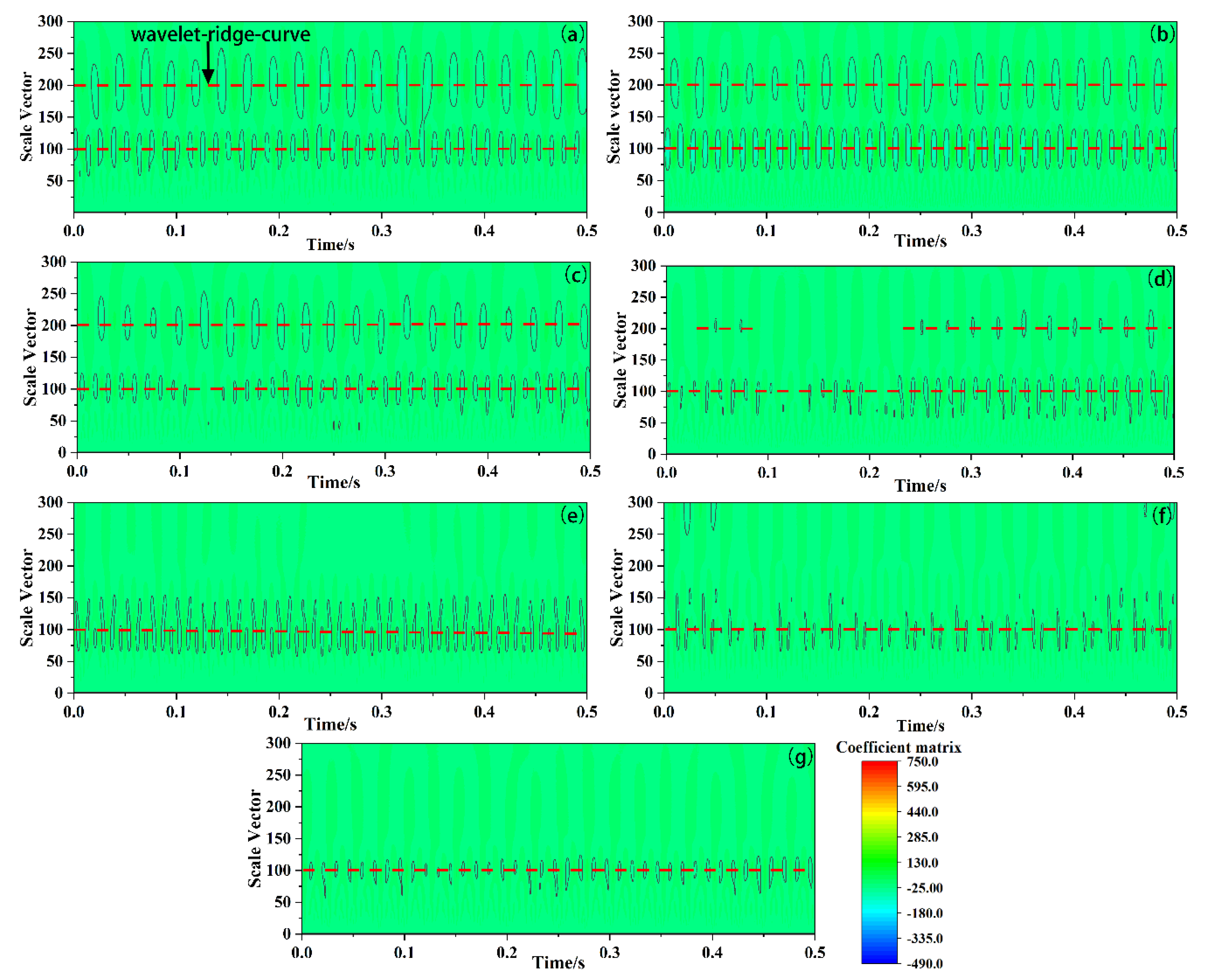
Figure 11 is the contour diagram of continuous wavelet transform coefficient of P-GMAW weld pool oscillation signal with different penetration status.
As shown in
Figure 11a–c, there were two continuous wavelet ridges in the contour diagram of the transform coefficient of oscillation of the full penetration pool. The scale vectors were 200 and 100, respectively, and with the Equation (2), the corresponding oscillation frequencies of the weld pool were 40 Hz and 80 Hz, respectively. As indicated by paper [
18]. The pool was a dynamic system excited by periodic signals under the impact of a fixed frequency, oscillating at the same or integer multiple of the pulse frequency (40 Hz). There were also two wavelet ridges with the same scale vector in the wavelets of the oscillating signals in the weld pool, but the wavelet ridge with the scale vector of 200 was inconsecutive as shown in
Figure 11d. As for partial penetration, only one wavelet ridge curve with the scale vector of 100 occurred in the contour diagram of transform coefficient, as shown in
Figure 11e–g, and the corresponding oscillation of the partly penetrated weld pool was 80 Hz. The corresponding wavelet skeleton at the wavelet ridge curves was the composition of the weld pool oscillation signal at this frequency [
17].
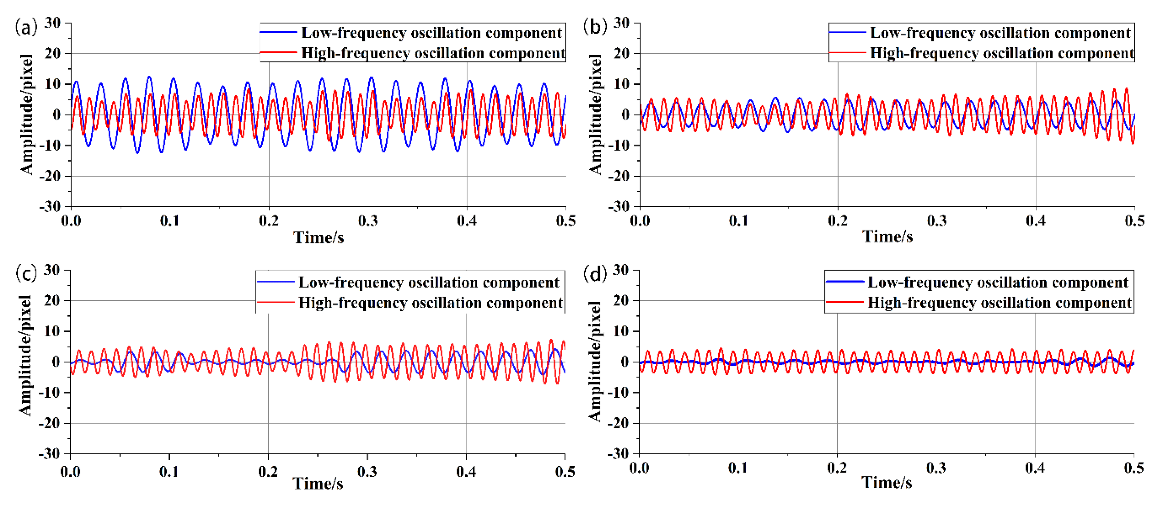
Figure 12 shows the composition of the weld pool oscillation signal at 40 Hz and 80 Hz with different penetration status.
As shown in
Figure 12, the amplitude of the component curve of the weld pool oscillation signal at 40 Hz and 80 Hz gradually decreased with the weld pool translated from full to partial penetration. The curves at 40 Hz fluctuated only in full and critical penetration. The oscillating signals of the full penetrated weld pool appeared low-frequency components (40 Hz) with large amplitude due to the lack of solid boundary constraint at the weld pool bottom, while the oscillating signals of the partly penetrated weld pools were only composed of high-frequency signals (80 Hz). As for critical penetration, the high-frequency component of the oscillation signal persisted, while the high-frequency component was not stable due to the variational boundary conditions.
These results suggest that different penetration status significantly affected the oscillation motion of the weld pool under the same impact. However, it was impossible to use the high-speed camera to extract the oscillation characteristic of the weld pool in practical production. The weld pool oscillation could change the arc length, thus affecting the voltage signal during the base time. Therefore, it was necessary to study the relationship between the voltage signal and the behavior of the weld pool during the base time.
3.2. The Link between the Voltage Signal and the Weld Pool Behavior
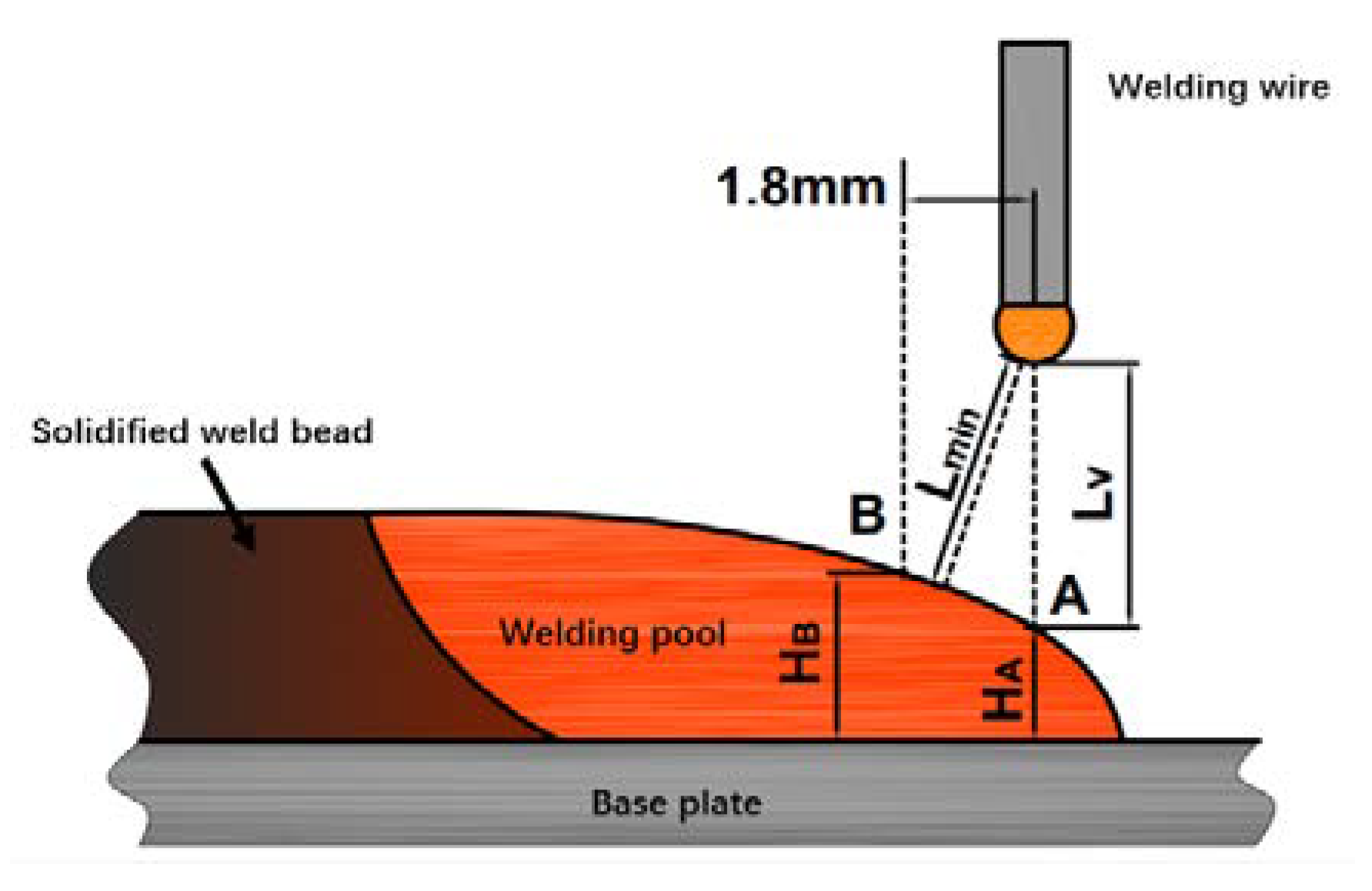
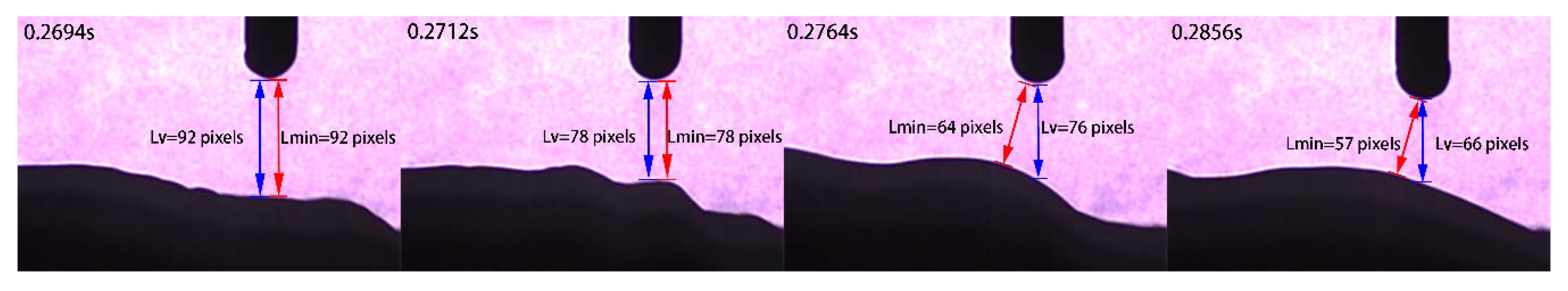
High-speed photographic images showed that the weld pool oscillation changed the relative position between the tip of the welding wire and the surface of the weld pool. It affected the arc length and caused the voltage signal fluctuation during the base time, as shown in
Figure 13. The shortest distance (L
V) and vertical distance (L
min) between the droplet and the pool during the base time were measured by image processing algorithm (as shown in
Section 2.1), and the relationship between the pool behavior and the voltage was analyzed.
As shown in
Figure 13, two main factors affected the relative position between the wire tip and the pool surface: (1) wire extension variation; (2) changes in height and curvature of weld pool surface. During the base time, the wire feeding speed was constant, while the wire could not melt, and the length of stick-out wire increased. The increased length of stick-out wire could lead to the arc length compression and the voltage drop over the wire increase, but the conclusion given in papers [
13,
19] shows that the change in the voltage drop over the wire extension during the base current time did little contribution to the voltage signal. It is commonly accepted that the arc voltage is proportional to the arc length. Each of the above exceptions could lead to arc voltage variation.
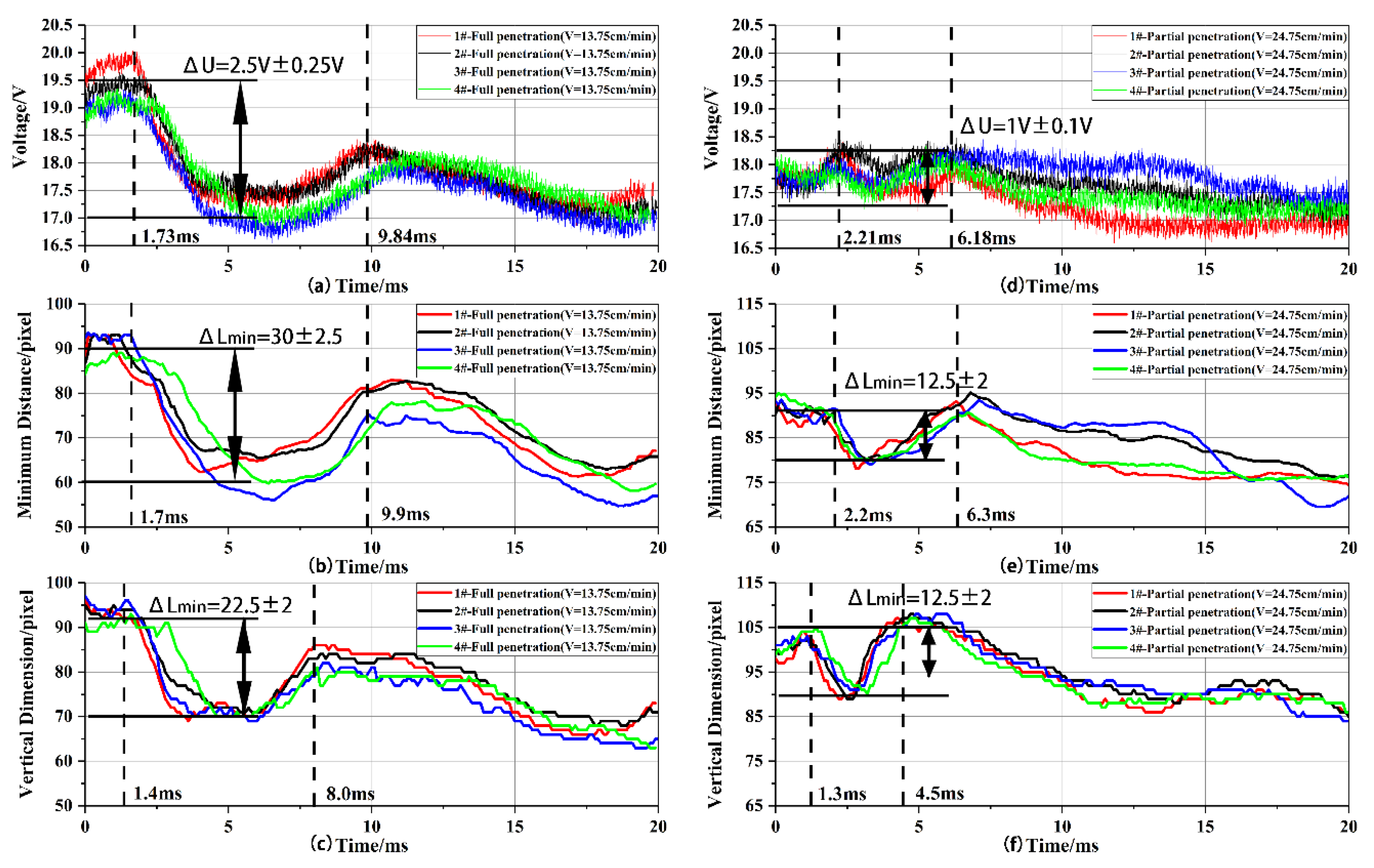
Figure 14 shows the synchronous curves of the voltage signal, the minimum distance (L
min) and the vertical dimension (L
V).
As shown in
Figure 14, the voltage signal curve, the minimum distance (L
min) curve and the vertical dimension (L
V) curve all showed an obvious trough for all penetration status. It was caused by the initial wave peak of the weld pool during the base time. The vertical dimension curve is the direct response to the weld pool motion (as shown in
Figure 2). The voltage signal curve had good consistency with the minimum distance curve. The starting and ending time of both troughs and shape of the curves were the similar as shown in
Figure 14a,b,d,e. It illustrates that the change of the shortest distance between the weld pool surface and the tip of the wire, which is the effective length of the arc, is the major factor of voltage fluctuation. However, the end time of the trough of the minimum distance curves and the voltage curves acted lag behind which of the voltage signal curves. It was caused by the transfer process of wave peaks on the surface of the weld pool. With the impact of the molten drop, a surface wave peak was formed and moved to the rear part of the weld pool. When the wave peak moved backwards and the pool under the welding wire fall back, the vertical dimension increased, while the minimum distance did not increase synchronously, as shown in
Figure 13. The minimum distance curve and the voltage signal curve lost the frequency characteristics of the pool oscillation due to the hysteresis of ending time of the trough, so the pool oscillation frequency cannot be extracted from the voltage signal.
As shown in
Figure 13 and
Figure 14, due to the curvature of the weld pool surface, there was some difference between ΔL
min and ΔL
V. while it could not be denied that ΔL
min had evident positive correlation with ΔL
V. Similarly, researchers have previously reported the non-proportional relationship between arc voltage and arc length [
19,
20,
21], while there were also significant positive correlations between arc voltage and arc length. Therefore, it can be inferred that the change of voltage during the base time (ΔU) can be used to sense the penetration status which is similar to the amplitude of the weld pool oscillation (described in
Section 3.1).
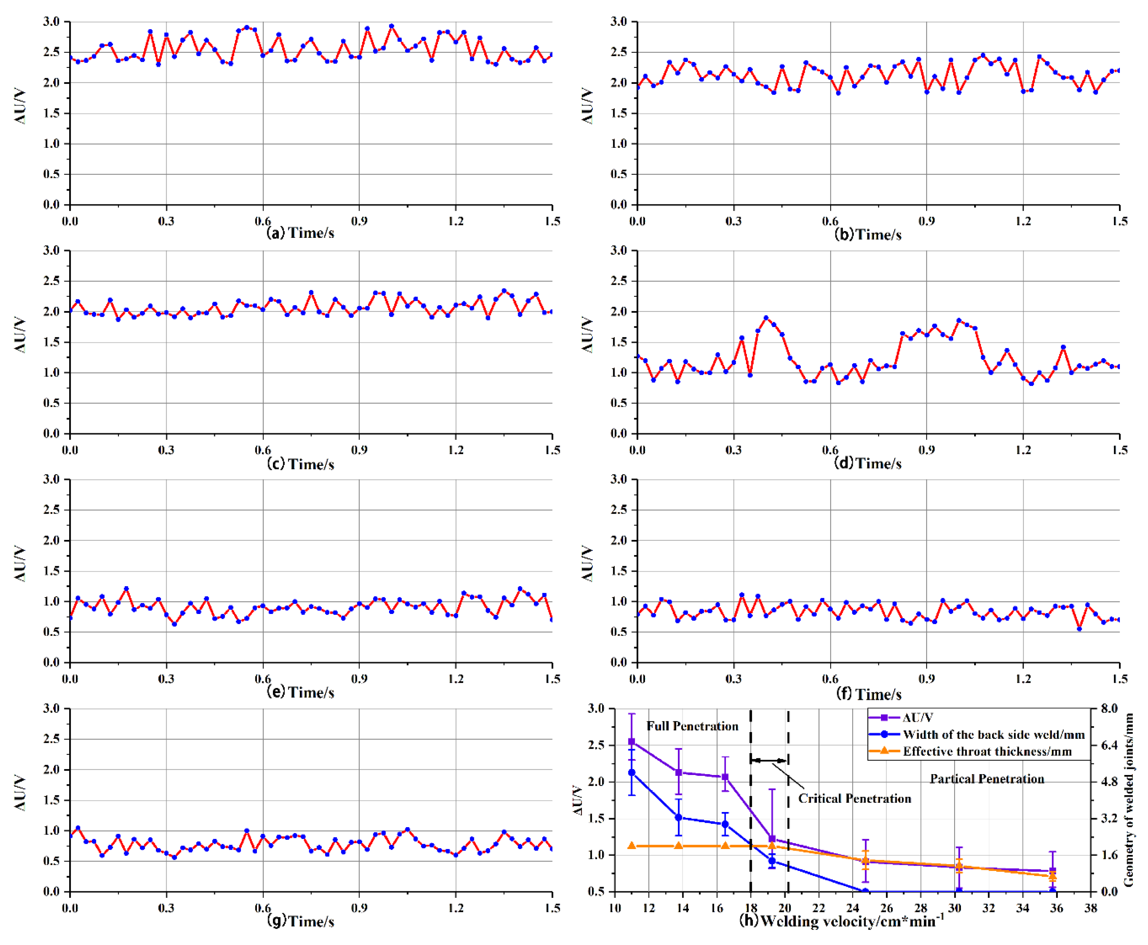
Figure 15 shows the curves of ΔU with time with different penetration statues.
ΔU was plotted with welding time at different penetration status, as shown in
Figure 15a–g. The trend of mean value and the error analysis of ΔUs at different penetration status are shown in
Figure 15g. With the decrease in ΔU, the status transform from the full penetration to the partial penetration, and an abrupt transition occurred of ΔU in the transition from full to critical penetration status which was similar to the trend of the oscillation amplitude. ΔU of full penetration was all greater than 2 V, while which of partial penetration was less than 1 V. As for critical penetration, the uncertainty of ΔU was the maxima relative to which of full penetration and partial penetration as shown in
Figure 15h. The range of ΔU was from 0.8 V–2 V due to nonconstant weld pool boundary conditions. The fluctuation amplitude of the arc voltage in the base duration (ΔU) reflects the penetration status. And ΔU occurs in every pulse base phase, which indicates that the curve of time and ΔU was a good indicator to sense weld penetration status. Under the experimental conditions in the present work, ΔU persistently greater than 2 V can be the threshold for full penetration. From the analyses made above, the constant watch of the curve of time and ΔU during P-GMAW was an efficient way to sensor the weld pool penetration status.


