Article

Reduction of Coupling Interface Degrees of Freedom in Mixed-Interface Component Mode Synthesis

1
School of Hydraulic Engineering, Dalian University of Technology, Dalian 116024, China
2
School of Civil Engineering, Dalian University of Technology, Dalian 116024, China
*
Author to whom correspondence should be addressed.
Appl. Sci. 2020, 10(8), 2759; https://doi.org/10.3390/app10082759
Submission received: 27 February 2020 / Revised: 4 April 2020 / Accepted: 14 April 2020 / Published: 16 April 2020

Abstract

:
A new coupling interface degrees of freedom (DOFs) reduction technique for the mixed-interface component mode synthesis (MCMS) method is proposed, which referred to as the MCMS-rid method. This approach employs a set of shape functions via the linear interpolation (LI) in finite element method (FEM) to realize interface nodal coordinate transformations for each substructure, and then only a small number of interpolation basic nodes (IBNs) will be involved in mode synthesis and the following dynamic analysis. Unlike the majority of available CMS methods that retain a full dimension of the coupling interface DOFs, the MCMS-rid method allows to reduce the coupling interface DOFs significantly and enhance the computational efficiency. Three numerical models, including a rectangular beam with two ends fixed, a non-rectangular beam with the button fixed and a simplified dam-foundation system with different material properties, are presented to demonstrate the computational accuracy and efficiency of the proposed method. The results indicate that favourable accuracy with a least number of retained DOFs involved in mode synthesis can be obtained for solving eigenvalue problems when compared with other MCMS methods. The optimal number and distribution of the IBNs are discussed on structural dynamic analysis as well. It is shown that the more the IBNs are involved in mode synthesis, the better the precision that will be received. Furthermore, when the sub-regions are nearly square, the precision is best.

1. Introduction

The finite element method (FEM) is one of the most effective way of solving structural dynamic problems. With a rapid increasing of computation capability, the demand for large scale FE models with huge number of degrees-of-freedom (DOFs) has raised even more quickly, which makes structural dynamic calculations much time-consuming. Hence, it is crucial to reduce computational cost, especially when physical structures are large and complex. A variety of model reduction methods have been developed during the last decades, and the focus in model reduction is mainly on reducing computational cost without too much accuracy being lost [1,2,3,4,5,6,7,8]. One of the most well known model reduction methods is component modes synthesis (CMS).
CMS was firstly proposed by Hurty, and it is an efficient method for analysing the dynamics of large, complex structures which are often described by separate interconnected components/substructures [9]. Hurty used three displacement modes (i.e., rigid-body, constraint and normal modes) to form a complete set of modes for each substructure, and he constructed a transformation relating component coordinates to system coordinates [10]. Craig and Bampoton improved the approach by Hurty, and they employed two forms of generalized coordinates: one is interface generalized coordinates that is related to constraint modes, the other is normal modes that is related to the free vibration modes of the substructures [11]. As completely restrained interfaces are imposed on each component at the connections, this approach can be classified as constrained-interface CMS (CCMS). Hou provided a new modal synthesis technique, in which the interface conditions used for determining component vibration modes were free-free and both compatibility and equilibrium at boundaries were satisfied for modal coupling [12]. This approach can be classified as free-interface CMS (FCMS). Benfield and Hruda developed a comprehensive method of component modal substitution that is applicable to redundant complex structures [13]. Using this method, the natural modes of vibration for each component are determined with both free-free and constrained interface conditions (known as MCMS). In general, CMS methods have relied on a bottom-up approach, which can be described by the following steps. First, partition the original structure into several substructures with same or different interface conditions; second, carry out the eigenvalue problem in each substructure, and generalized mass, stiffness, damping matrices are determined; third, transform the component physical coordinates to the modal coordinates by reduced normal modes; forth, assemble all the components based on the displacement-compatibility or/and force-equilibrium at the connections; fifth, carry out the reduced global eigenvalue problem. As the number of the retained component modes is substantially smaller than the global physical DOFs, the computational size of modal synthesis is greatly reduced [14].
In any type of the CMS methods, the most important and difficult task is choosing an appropriate reduced component modes involving modal reduction and mode synthesis, and this continues to be an area of research [15,16,17,18,19,20,21,22]. Lots of work have been done to make improvements on modal reduction of internal DOFs [23,24,25,26,27], but no order reduction is performed on the boundary. Though the internal DOFs dominate the FE models of substructures, they are greatly reduced by the process of coordinate transformations based on traditional CMS theory, as only a small number of low-frequency modes are truncated. However, if the number of substructures is increasing, or if the coupling interface is large and the FE mesh is fine, the coupling interface DOFs will rule the following works, and retaining a full dimension of the coupling interface DOFs will definitely lower the computational efficiency of mode synthesis. Thus, it is necessary to establish an approach to reduce the number of interface DOFs without too much accuracy diminished, and this will result in incomplete boundary conditions [28]. To date, different interface reduction methods have been proposed by various researchers, and most of them can be classified by two categories. One is to replace full size of constrain modes by a subset of interface modes via performing a second modal analysis related to the interface DOFs [29,30,31]; the other is to introduce additional variables such as Lagrange multipliers that represent the interface generalized vectors [32,33,34,35,36]. However, in general, the validity of these methods are heavily rely on a good selection of special interface modes, and they may be time-consuming by performing supplementary modal analysis for the interface modes.
In this work, a new coupling interface degrees of freedom reduction technique for the MCMS method (referred to as the MCMS-rid method) is established properly. In MCMS-rid, a set of interpolation functions via the linear interpolation (LI) [37,38] suitable for both nodal displacements and nodal forces are built, and then the corresponding coordinate transformation matrices for constrained interfaces and free interfaces are derived respectively. Different from the methods aforementioned, the interpolation functions representing the reduced interface DOFs are established based on the initial interface DOFs of substructures, in which no additional variables or supplementary modal analysis are needed. Therefore, the corresponding coordinate transformation can be carried out within each substructure before assembling or even in individual processors of a parallel computer. The other advantage of this method is that the number of the retained interface DOFs are distributed between the separate substructures in an optimal sense.
It should be noted that we seek a consistently reduced model for MCMS, whose size depends exclusively on the physics of the problem rather than the FE models. Thus, the presented work is aimed to propose a coupling interface DOFs reduction procedure which has to satisfy the following two conditions: (i) the numerical precision with respect to the full interface dimension model should be kept in an acceptable level, and (ii) the interface modes selection shall be based on a robust criterion. The efficiency of the approach is demonstrated by eigenvalue analyses of three typical numerical examples, including a rectangular beam with two ends fixed, a non-rectangular beam with the button fixed and a simplified dam-foundation system. The optimal number and distribution of the interpolation nodes are discussed on structural dynamic analysis as well.

2. A Brief Review of the Traditional MCMS

This section provides a brief review of the traditional MCMS proposed by Benfield and Hruda (also called the B-H method for short) [13]. In a global domain, the linear equation of motion (EOM) of a N-DOFs structure is written as
M u ¨ + C u ˙ + K u = f
where M , C and K are the mass matrix, the damping matrix and the stiffness matrix of the global structure, respectively; u ¨ , u ˙ and u are the acceleration vector, the velocity vector and the displacement vector, respectively; f is the external force vector.
In the B-H method, the original system is divided into two groups: master substructures and slave substructures. All the substructures are non-overlapping so that each node belongs to exactly one substructure except for the nodes on the coupling interface. In Figure 1, only one master substructure and one slave substructure are shown as demonstration. Different interconnection conditions are imposed on each part, where the interconnection of the master substructure is constrained while that of the slave substructure is free. Then, Equation (1) can be rewritten in block matrices as
M f I 0 0 0 M B 0 0 0 M c I u ¨ f I u ¨ B u ¨ c I + C f I 0 0 0 C B 0 0 0 C c I u ˙ f I u ˙ B u ˙ c I + K f I 0 0 0 K B 0 0 0 K c I u f I u B u c I = f f I f B f c I
in which, subscripts c and f indicate the master substructure with constrained interconnections and the slave substructure with free interconnections, respectively; superscripts I and B indicate the internal DOFs and the interface DOFs. The linear equations of motion of each structure are,
M f I 0 0 M f B u ¨ f I u ¨ f B + C f I 0 0 C f B u ˙ f I u ˙ f B + K f I 0 0 K f B u f I u f B = f f I f f B + 0 g f
M c I 0 0 M c B u ¨ c I u ¨ c B + C c I 0 0 C c B u ˙ c I u ˙ c B + K c I 0 0 K c B u c I u c B = f c I f c B + 0 g c
where, g is the reaction force vector relative to the coupling DOFs of the substructure.
The first coordinate transformations that transforming the physical coordinates u to generalized coordinates q are done in each substructure according to the different interconnection conditions. That is,
u f = u f I u f B = Φ k I Φ k B q k = T f 1 q k
u c = u c I u c B = Φ m Φ c 0 I q m u c B = T c 1 q m u c B
where Φ k and Φ m are the truncated normal mode involving in mode synthesis; Φ c is the constrained mode; T 1 is the first coordinate transformation matrix. The corresponding generalized stiffness and mass matrix can be written as
K f ( 1 ) = T f 1 T K f T f 1 , M f ( 1 ) = T f 1 T M f T f 1
and
K c ( 1 ) = T c 1 T K c T c 1 , M c ( 1 ) = T c 1 T M c T c 1
In the B-H method, only the displacement-compatibility is involved in mode synthesis. That is,
u f B = Φ k B q k = u c B
Substituting Equation (9) into Equation (6), the second coordinate transformation for the slave substructure and the corresponding generalized stiffness and mass matrix can be expressed as
q m u c B = I m 0 0 Φ k B q m q k = T c 2 q m q k
K c ( 2 ) = T c 2 T K c ( 1 ) T c 2 , M c ( 2 ) = T c 2 T M c ( 1 ) T c 2
Assembling all the generalized stiffness and mass matrices of the master and slave substructures, the global reduced stiffness and mass matrices are
K ¯ = K f ( 1 ) + K c ( 2 ) , M ¯ = M f ( 1 ) + M c ( 2 )
The uncoupled eigenvalue problem is shown in Equation (13), and the order number of the eigenvalue problem equals to ( m + k ) .
K ¯ ω 2 M ¯ q m q k = 0

3. Normal Mode Correction for the Master Substructure

As the effect of the slave substructure on the normal modes of the master substructure is ignored in B-H method, the calculation accuracy of system dynamic characteristics is unsatisfactory. Some revised methods [39,40,41] are then proposed for MCMS method, and most of them focus on correcting the normal modes of the master substructure.

3.1. Static Condensation of the Slave Substructure

One way of normal mode correction is static condensation [39], which imposes the effect of the slave substructure on the coupling interface of the master substructure. The coordinate transformation of static condensation can be written as
u c = u c I u c B = Φ c I u c B = Ψ c u c B
Then, the generalized stiffness and mass matrices of the slave substructure are
K c * = Ψ c T K c Ψ c , M c * = Ψ c T M c Ψ c
Adding K c * and M c * on the original stiffness and mass matrices of the master substructure that corresponds to the coupling interface, i.e., K f B B and M f B B . The revised stiffness and mass matrices of the master substructure and the eigenvalue problem are,
K f * = K f + K c * , M f * = M f + M c *
K f * ω 2 M f * ϕ = 0
In this case, the order number of the eigenvalue problem is totally as same as the master substructure.

3.2. Partition of the Master Substructure

Another way to correct normal modes is partitioning the master substructure by the fundamental concept of FCMS method [12]. For a free-interface substructure, the modal transformation consists of two groups of modes, including the normal modes Φ and the residual attachment mode Ψ d . The normal mode Φ can also be partitioned into two categories: the truncated normal mode Φ k that is kept for modal analysis and the higher abandoned mode Φ d that will not involve in mode synthesis. Thus, the first coordinate transformation can be rewritten as
u f = Φ k Ψ d q k g f = T f 1 q k g f
Ψ d = Φ d Λ d 1 Φ d B T
where, Φ d B and Λ d are the abandoned normal mode corresponding to the coupling interface DOFs and the remaining eigenvalue, respectively.
The revised generalized stiffness and mass matrices of the master substructure then can be obtained as follows
K f ( 1 ) = T f 1 T K f T f 1 , M f ( 1 ) = T f 1 T M T f 1
Assembling all the generalized stiffness and mass matrices of the master substructure Equation (20) and that of the slave substructure Equation (8), the eigenvalue problem for the reduced global system will be done. However, as the generalized coordinates here consist of four categories: q k , q m , g f and u c B , an extra coordinate transformation is needed to eliminate the independent ones in the truncated normal modes.

3.3. Mode Synthesis in the Revised MCMS Method [40]

Mode synthesis process for the revised MCMS method is much more complicate than the CCMS method and FCMS method as two different kinds of interface (i.e., constrained-interface and the free-interface) should be coupled. In this case, the coordinate transformation modes contain truncated mode Φ , including Φ m for the constrained-interface substructure and Φ k for the free-interface substructure, constrained mode Φ c and residual attachment mode Ψ d simultaneously. The displacement-coordination and force-equilibrium between adjacent substructure can be written as
u f B = u c B
g f + g c = 0
When describing u f B by the generalized coordinates, the displacement-coordination in Equation (21) can be stated as follows:
u c B = Φ k B q k + Ψ d B g f
where, Φ k B and Ψ d B are the truncated modal matrix and the remaining adherent mode relating to all the interface DOFs for the master substructure. Multiplying the both sides of Equation (23) by Ψ d B 1 , then g f can be written as
g f = Ψ d B 1 u c B Ψ d B 1 Φ k B q k
For the slave substructure, the following equation of motion is used to obtain the pseudo static matrix Φ c ,
K c I I K c I B K c B I K c B B u c I u c B = 0 g c
The interface force g c can be obtained from the second equation in Equation (25),
g c = K c B B + K c B I · Φ c u c B + K c B I Φ m q m
Substituting Equations (24) and (26) into Equation (22) leads to
u c B = P 1 P 2 q k q m
where,
P 1 = I + Ψ d B · K c B B + Ψ d B · K c B I · Φ c 1 · Φ k B
P 2 = Ψ d B 1 + K c B B + K c B I · Φ c 1 · K c B I · Φ m
Substituting Equation (27) into Equation (24), then g f becomes
g f = Q 1 Q 2 q k q m
where,
Q 1 = Ψ d B 1 · P 1 Φ k B
Q 2 = Ψ d B 1 · P 2
Thus, the second coordinate transformation for the two substructures are
q k g f = I k 0 Q 1 Q 2 q k q m = T f 2 q k q m
q m u c B = 0 I m P 1 P 2 q k q m = T c 2 q k q m
After the second coordinate transformation, the generalised stiffness and mass matrices of each substructure are written as follows:
K f ( 2 ) = T f 2 T K f ( 1 ) T f 2 , M f ( 2 ) = T f 2 T M f ( 1 ) T f 2
and
K c ( 2 ) = T c 2 T K c ( 1 ) T c 2 , M c ( 2 ) = T c 2 T M c ( 1 ) T c 2
The generalized stiffness and mass matrices of the global system can be assembled directly from Equations (37) and (38), and then eigenvalue problems can be solved by Equation (39).
K = K f ( 2 ) + K c ( 2 )
M = M f ( 2 ) + M c ( 2 )
K ω 2 M q = 0
From above discussions we can see that, the coordinate transformations for mode synthesis can be done in each substructure separately, and then it is easy to assemble the component generalized stiffness and mass matrices into the global ones according to the truncated normal modes.

4. Reduction of the Coupling Interface DOFs

4.1. Formulation

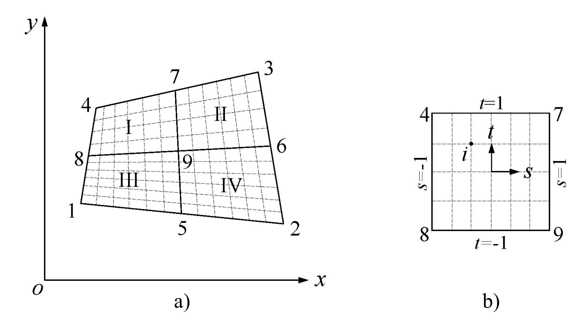
During the aforementioned coordinate transformations, the component physical coordinates are represented by modal coordinates for both master and slave substructures. The generalized DOFs involving in modal analysis consist of the full dimension of the coupling interface DOFs and a small part of the truncated internal DOFs. The number of the generalized DOFs can still be large when the coupling interface of the substructure is huge and complex. On the one hand, a large number of DOFs involving in modal analysis will lower the computational efficiency; on the other hand, it is impossible to load on each DOF on the connections in a structural testing. Therefore, reducing the coupling interface DOFs of substructures is quite necessary. In this section, the displacement interpolation formulation in FEM is utilized to reduce the coupling interface DOFs. Without loss of generality, a two-dimensional interface, a plane as shown in Figure 2a, is taken as an example to set up interpolation functions and formulations, which can be easily extended to solve three-dimension problems.
Dividing the coupling interface into four sub-regions (I ∼ IV), as shown in Figure 2a. The nodes 1∼9 is defined as interpolation basic nodes (IBNs), and then the force and displacement of each node i (Figure 2b) can be described approximately by that of the IBNs by a set of shape functions N s , t [42]. The displacement or force interpolation formulations of the rectangular element are
g x i = n = 1 4 N n ( s i , t i ) g x n g y i = n = 1 4 N n ( s i , t i ) g y n g z i = n = 1 4 N n ( s i , t i ) g z n o r u x i = n = 1 4 N n ( s i , t i ) u x n u y i = n = 1 4 N n ( s i , t i ) u y n u z i = n = 1 4 N n ( s i , t i ) u z n
where, u i and g i are force and displacement vectors of node i in the global coordinate system; x, y and z are the x, y and z-direction; n is the number of IBNs in the sub-region that node i is in; N n ( s i , t i ) is the shape function. Based on the rectangular element theory in FEM, linear interpolation of finite elements is stated more clearly by a natural coordinate system, and interpolation functions can be expressed as follows
N 1 = 1 4 ( 1 s i ) ( 1 t i ) N 2 = 1 4 ( 1 + s i ) ( 1 t i ) N 3 = 1 4 ( 1 + s i ) ( 1 + t i ) N 4 = 1 4 ( 1 s i ) ( 1 + t i ) , s i = ( x i X 0 ) / m t i = ( y i Y 0 ) / n X 0 = ( X 1 + X 3 ) Y 0 = ( Y 1 + Y 3 ) m = | X 1 X 3 | / 2 n = | Y 1 Y 3 | / 2
where, ( X i , Y i ) , ( i = 0 , 1 , 2 , 3 , 4 ) are the coordinates of the central node and IBNs in x-y coordinate plane.
The nodal displacement or force vector relative to the coupling interface DOFs of the constrained-interface or the free-interface substructure can be obtained from assembling the interpolation transformation of all re-regions. There are
g f = A g f n o r u c B = B u c n
in which, u n and g n are the displacement and force vectors relative to the IBNs of the coupling interface; A and B are transformation matrices that represent the relations between all the interface nodes and the IBNs.
Then the coordinate transformations for the constrained-interface or free-interface substructure can be written in vectorized form, and the generalized stiffness and mass matrices are computed as followings:
q k g f = I k 0 0 A q k g f n = T f r η k o r q m u c B = I m 0 0 B q m u c n = T c r η c
K f r = T f r T K f ( 1 ) T f r o r K c r = T c r T K c ( 1 ) T c r
M f r = T f r T M f ( 1 ) T f r o r M c r = T c r T M c ( 1 ) T c r
It is clearly that the coordinate transformation for reducing the interface DOFs in Equation (43) can be conducted within each substructure before assembling. The interpolation functions ( A and B ) chosen for the reduction only lies on the coupling conditions of the substructure, so that the proposed method can be easily extended to other situations such as non-contact interface or systems with connection substructure.

4.2. Mode Synthesis with Reduced Coupling Interface DOFs

The process of mode synthesis with reduced coupling interface DOFs is basically as same as mentioned above (i.e., Equations (21)–(34)), except that the coordinates involving in docking are u n and g n instead of u B and g . Assuming that the shape function and the number of IBNs chosen for all the substructures are same, so that A = B . Substituting Equation (42) into Equations (21) and (22) leads to
u f n = u c n
g f n + g c n = 0
And then, u c n in Equation (27) and g f n in Equation (30) can be rewritten as
u c n = P 1 r P 2 r q k q m
g f n = Q 1 r Q 2 r q k q m
where,
P 1 r = K c B B · A · A T · K c B I · Φ c · A + A · Ψ d n 1 A T · A 1 · A · Ψ d n 1 · Φ k n
P 2 r = K c B B · A · A T · K c B I · Φ c · A + A · Ψ d n 1 A T · A 1 · K c B I · Φ m
Q 1 r = Ψ d n 1 A T · A · P 1 r
Q 2 r = Ψ d n 1 A T · A · P 2 r Ψ d n 1 · Φ k n
Thus, the coordinate transformations with reduced coupling interface DOFs for each substructure are
q k g f n = 0 I k Q 1 r Q 2 r q k q m = T f 3 q k q m
q m u c n = I m 0 P 1 r P 2 r q k q m = T c 3 q k q m
After the third coordinate transformation, the generalised stiffness and mass matrices of each substructure are written as follows:
K f ( 3 ) = T f 3 T K f r T f 3 , M f ( 3 ) = T f 3 T M f r T f 3
and
K c ( 3 ) = T c 3 T K c r T c 3 , M c ( 3 ) = T c 3 T M c r T c 3
The generalised stiffness and mass matrices of the global system can be assembled directly as follows, and then eigenvalue problems can be solved by Equation (60).
K = K f ( 3 ) + K c ( 3 )
M = M f ( 3 ) + M c ( 3 )
K ω 2 M q = 0

5. Numerical Examples

In this section, we evaluate the performance of the MCMS-rid method using three numerical examples: a rectangular beam, a non-rectangular beam and a dam-foundation system.

5.1. Example 1

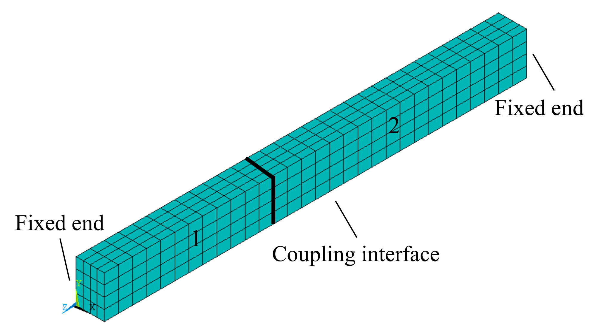
A beam (length = 6 m, width = 0.6 m and height = 0.4 m) with two fixed ends is taken as example 1. The three-dimensional elastic FE model with 725 nodes and 2175 DOFs is shown in Figure 3. The material properties of the beam are: ρ = 2500 kg/m 3 , E = 30 GPa and ν = 0.3.
We divide the beam into two components (numbered “1” and “2”), and constrain the coupling interface of the component 1 while set free that of the component 2. As shown in Figure 4a, the coupling interface is a rectangular with 25 nodes and 75 DOFs. In the following modal analysis based on MCMS method, the number of truncated normal modes is 10 for component 1 and 5 for component 2, respectively.
We firstly compare eigenvalue features of the MCMS-rid method with other three existing MCMS methods, including the B-H method, B-H method with normal mode correction (BHC) and the revised MCMS method with full coupling interface DOFs (MCMS-fid) [43]. For the MCMS-rid method, the coupling interface is divided into four sub-regions (Figure 4b) and the corner nodes of each sub-region are chosen as IBNs. Thus, the number of the coupling interface DOFs are reduced from 75 to 27. The first eight natural frequencies calculated by each method are listed in Table 1, where “FEM” indicates the exact numerical solutions of the whole beam. The relative errors of the natural frequencies for MCMS methods are also done by Equation (61), and the “Method” in the equation refers to “B-H, BHC, MCMS-fid and MCMS-rid”. The numbers of the retained DOFs involved in docking and mode synthesis for each method are also shown in Table 1 (in parenthesis).
e i = f Method i f FEM i f FEM i × 100 % , ( i = 1 , 2 , . . . , 8 )
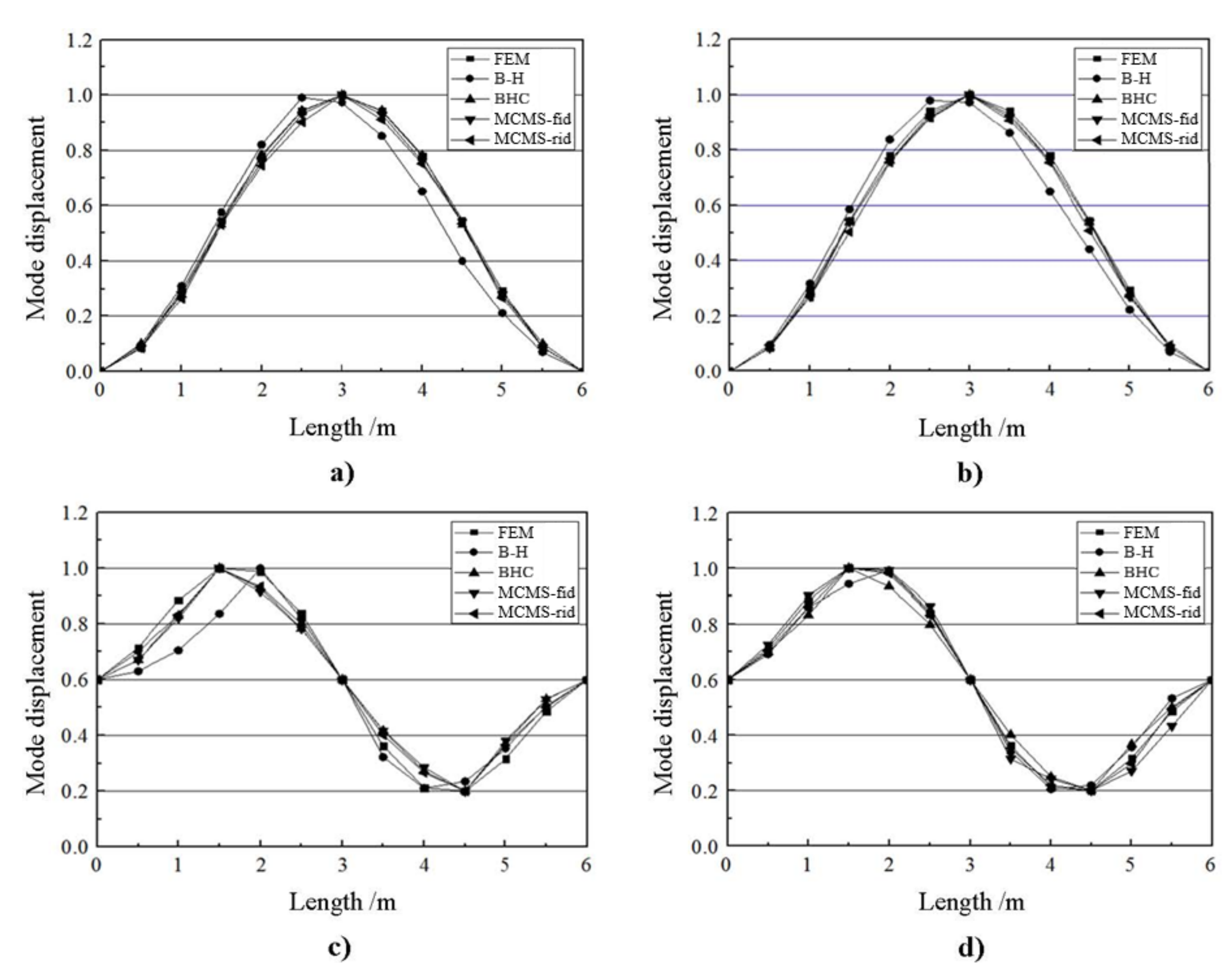
From Table 1 we can see that, the accuracy of the B-H method is worst of all. It is because the B-H method ignores the influence of higher-order of the master substructure on the modal synthesis. The accuracy of the BHC method has been improved by considering the effect of normal modes correction on the dynamic characteristics of the system. Though the MCMS-rid method is less accurate than the MCMS-fid method, it improves the computational efficiency enormously by using only 69 DOFs. Also, the relative errors for the MCMS-rid method are less than 10%, which ensures the accuracy and reasonableness of the modal analysis. Figure 5 gives the first four mode shapes of the beam by using different methods.
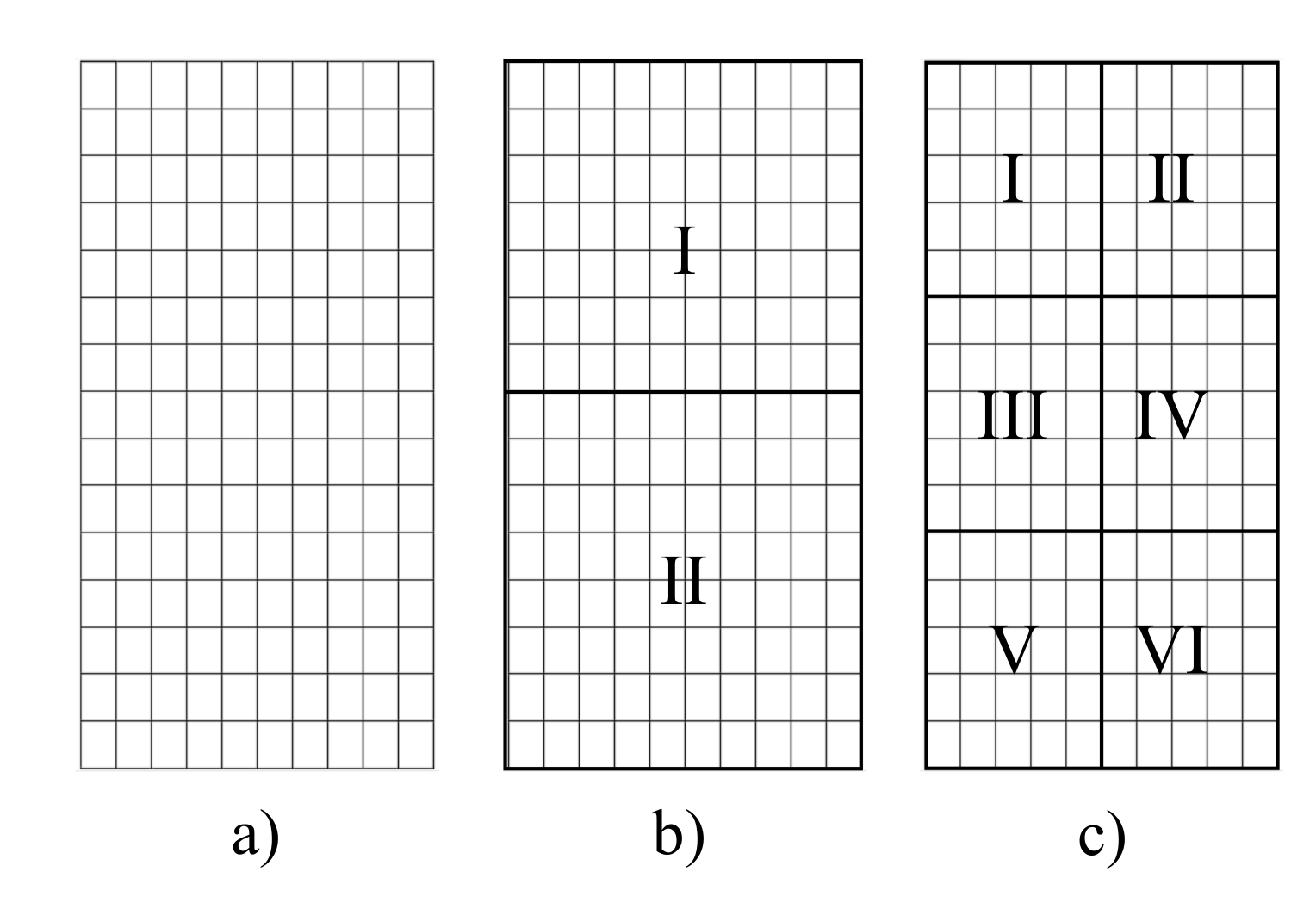
The effect of the number and distribution of the IBNs on the eigenvalue performance of the MCMS-rid method is studied as well. As shown in Figure 4, four interpolation schemes are considered for mode synthesis. For scheme (a), all the coupling interface nodes are involved in docking of substructures, i.e., MCMS-fid. For case (c), the four corner nodes of the coupling interface are assigned as the IBNs (only one sub-region). In case (b) and (d), the coupling interface is divided into four sub-regions with different shape, and all the corner nodes of the sub-regions are assigned as the IBNs. Scheme (a) is taken as exact solutions, and the relative errors for other schemes are calculated by Equation (62), where “Scheme” in the equation indicates “(b), (c) and (d)”.
e i = f Scheme i f ( a ) i f ( a ) i × 100 % , ( i = 1 , 2 , . . . , 8 )
The first eight natural frequencies of the beam are listed in Table 2. The results indicates that both the number and distribution of the interpolation basic nodes have great influence on the accuracy of the MCMS-rid method. The accuracy is improved as the number of the IBNs chosen for mode synthesis are increasing. Meanwhile, the shape of sub-regions are also a key factor for precision. Though the number of the IBNs in scheme (b) is nine while that in scheme (d) is 10, the numerical precision of (b) is better. That is, the precision is better when the sub-regions divide the coupling interface evenly and the shape of sub-regions are nearly square. The validity of the MCMS-rid method is also verified by using the Modal Assurance Criterion (MAC) and the Frequency Response Functions (FRF) comparisons. The equation of MAC is,
MAC = ϕ M C M S r i d T ϕ M C M S f i d 2 ( ϕ M C M S r i d T ϕ M C M S r i d ) ( ϕ M C M S f i d T ϕ M C M S f i d )
where ϕ M C M S f i d and ϕ M C M S r i d are the physical partitions of the eigenvectors by the MCMS-fid method and the MCMS-rid method, respectively.
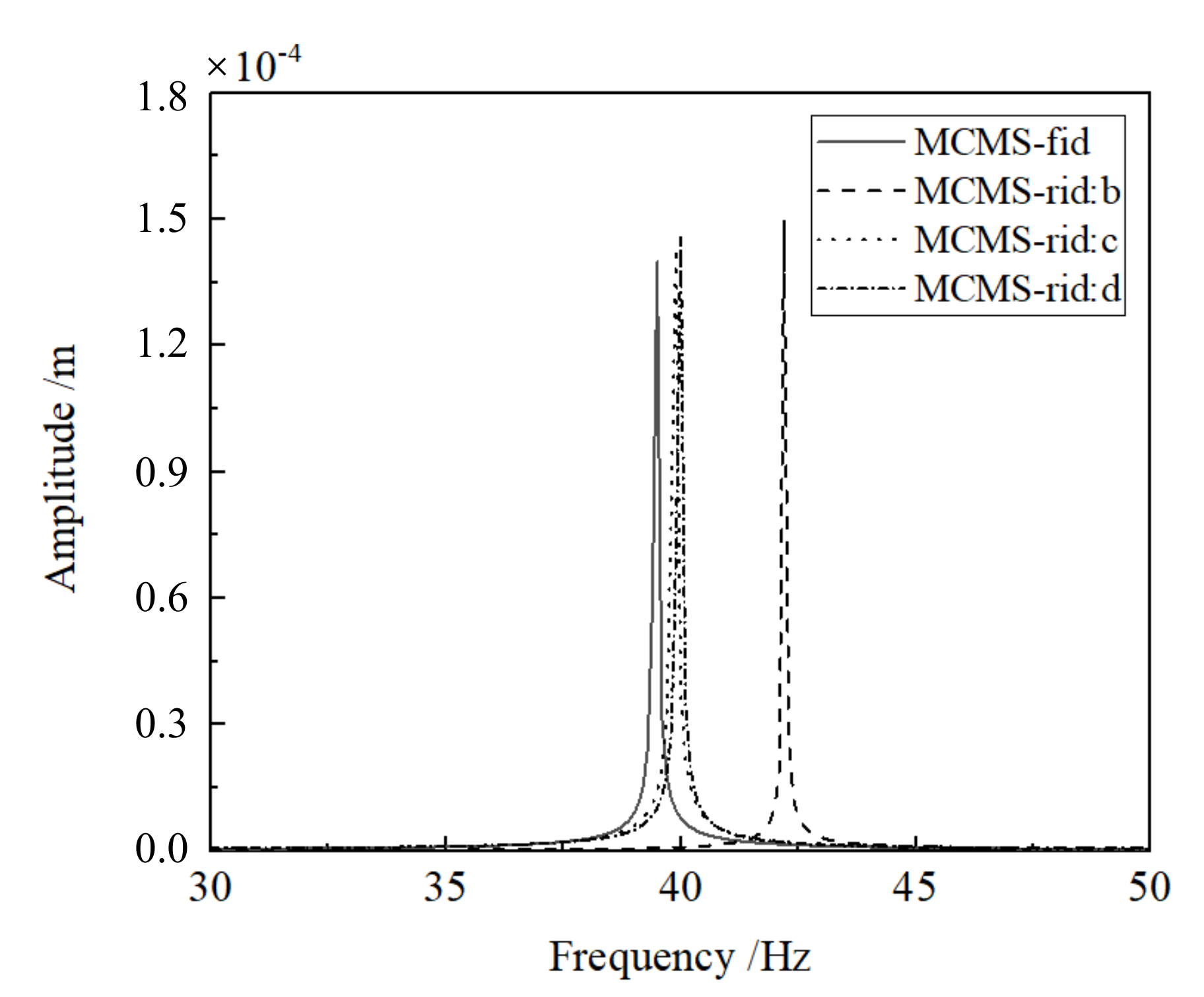
The MAC between the modes by the MCMS-fid method and the MCMS-rid method with different interpolation schemes are plotted in Figure 6. It is seen that the mods of the MCMS-fid method and the MCMS-rid method are identical to each other, which gives confidence in the MCMS-rid method. The FRF comparisons, shown in Figure 7, are conducted by applying a harmonic excitation at excitation level of 1N in the Y direction in the middle of the beam. It illustrates that the MCMS-rid method with nine and 10 IBNs have better capability to capture the dynamic responses of the beam than the MCMS-rid method with four IBNs in terms of both the resonance frequency and its corresponding amplitude, confirming that both the number and distribution of the IBNs have a huge effect on the validity of the proposed method.

5.2. Example 2

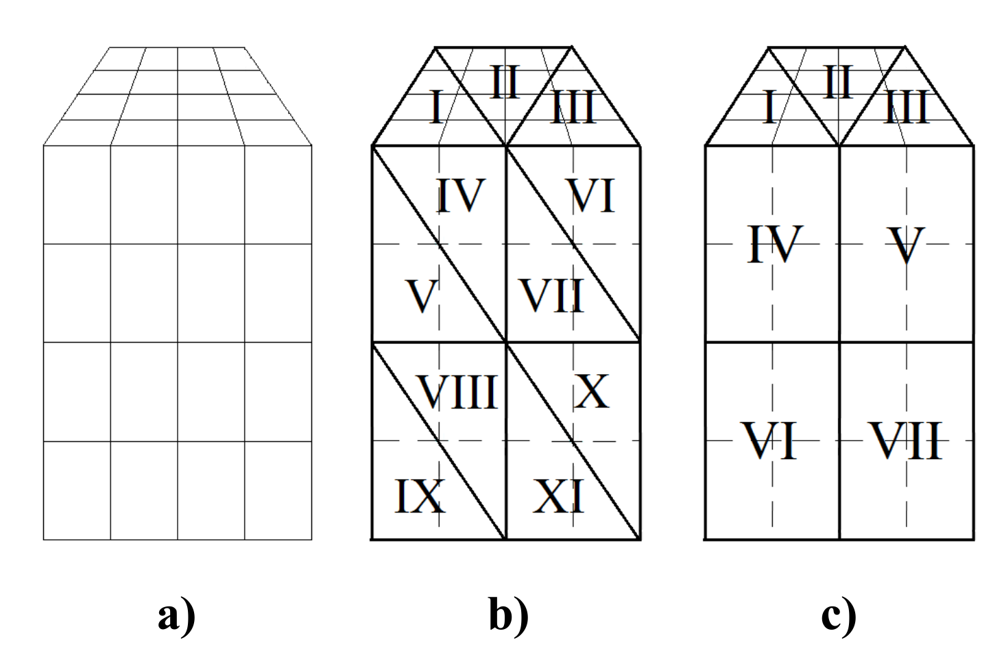
The second example is a three-dimensional elastic body with a polygon section (H = 7 m, W = 4 m and L = 12 m). The material properties of the beam are: ρ = 1800 kg/m 3 , E = 10 MPa and ν = 0.3. The nodes on the base of the model are fixed. The FE model with 315 nodes and 945 DOFs in total is shown in Figure 8. The overall model is divided into two components numbered “1” and “2”, and two interpolating schemes (Figure 9c) are adopted. In scheme (b), only triangular interpolation sub-regions are introduced. While in scheme (c), both quadrangle and triangular interpolation sub-regions are used. All the corner nodes of the sub-regions for scheme (b) and (c) are assigned as the IBNs, with the number of 11.
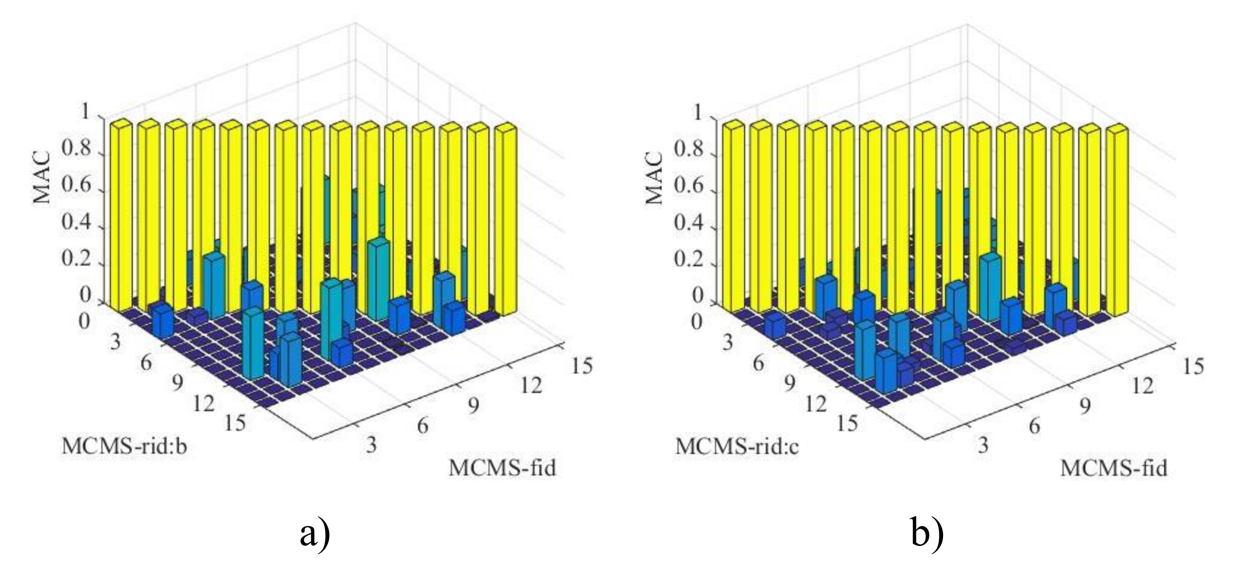
Based on the results by the MCMS-fid method (scheme (a)), the relative errors of the first eight natural frequencies of the elastic body FE model are listed in Table 3. Figure 10 shows the MAC between the modes of the MCMS-fid method and the MCMS-rid method (schemes (b) and (c)). The FRF comparisons are conducted by applying a harmonic excitation at excitation level of 1N in the X direction in the middle of the beam, and the results for the first mode are plotted in Figure 11. All these results indicate that, the MCMS-rid method developed in this paper is still effective and suitable for the non-rectangle beam. Though the same number of the IBNs are kept in the two schemes, the numerical precision of (c) is better than that of (b), which means that the shape of the sub-region has important influence on the numerical precision. In general, quadrangle interpolation sub-regions are more suitable for interface DOFs reduction. However, triangular interpolation sub-regions are still needed especially when the coupling interface is irregular.

5.3. Example 3

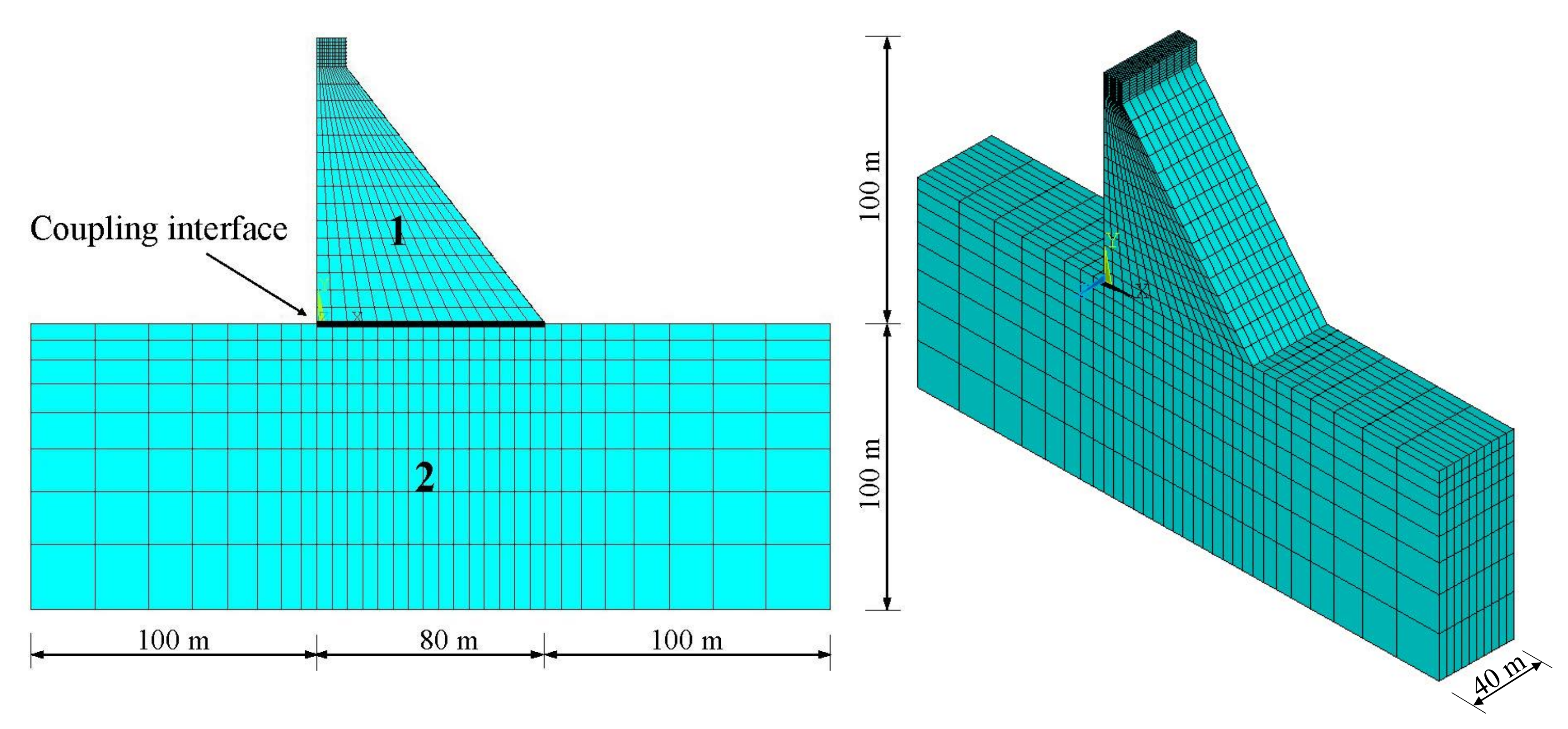
A simplified dam-foundation system is introduced here to study the accuracy and computational efficiency of the MCMS-rid method when the DOFs of the FE model is huge and the material properties of the substructures are different. The dimensions of the FE model are shown in Figure 12, and the dam is defined as constrained substructure “1” while the foundation is free substructure “2”. The material properties and the numbers of elements, nodes and DOFs of the substructures are listed in Table 4 and Table 5 respectively. Figure 13 shows the shape of the coupling interface and two interpolating schemes are adopted, in which 6 IBNs with 18 coupling interface DOFs (Figure 13b) and 12 IBNs with 36 coupling interface DOFs (Figure 13c) are chosen for substructure docking.
The number of the truncated normal modes for substructure “1” is 100 while for substructure “2” is 200, so that the DOFs kept for mode synthesis are reduced down to 828 (MCMS-fid), 318 (MCMS-rid:b) and 336 (MCMS-rid:c) respectively, which are almost the 4.15%, 1.60% and 1.69% of the original FE models size. The computational costs for the MCMS-fid, MCMS-rid:b and MCMS-rid:c method are shown in Table 6, which indicate that reducing the number of interface DOFs is responsible for the further saving of computational efforts when compared to FEM.
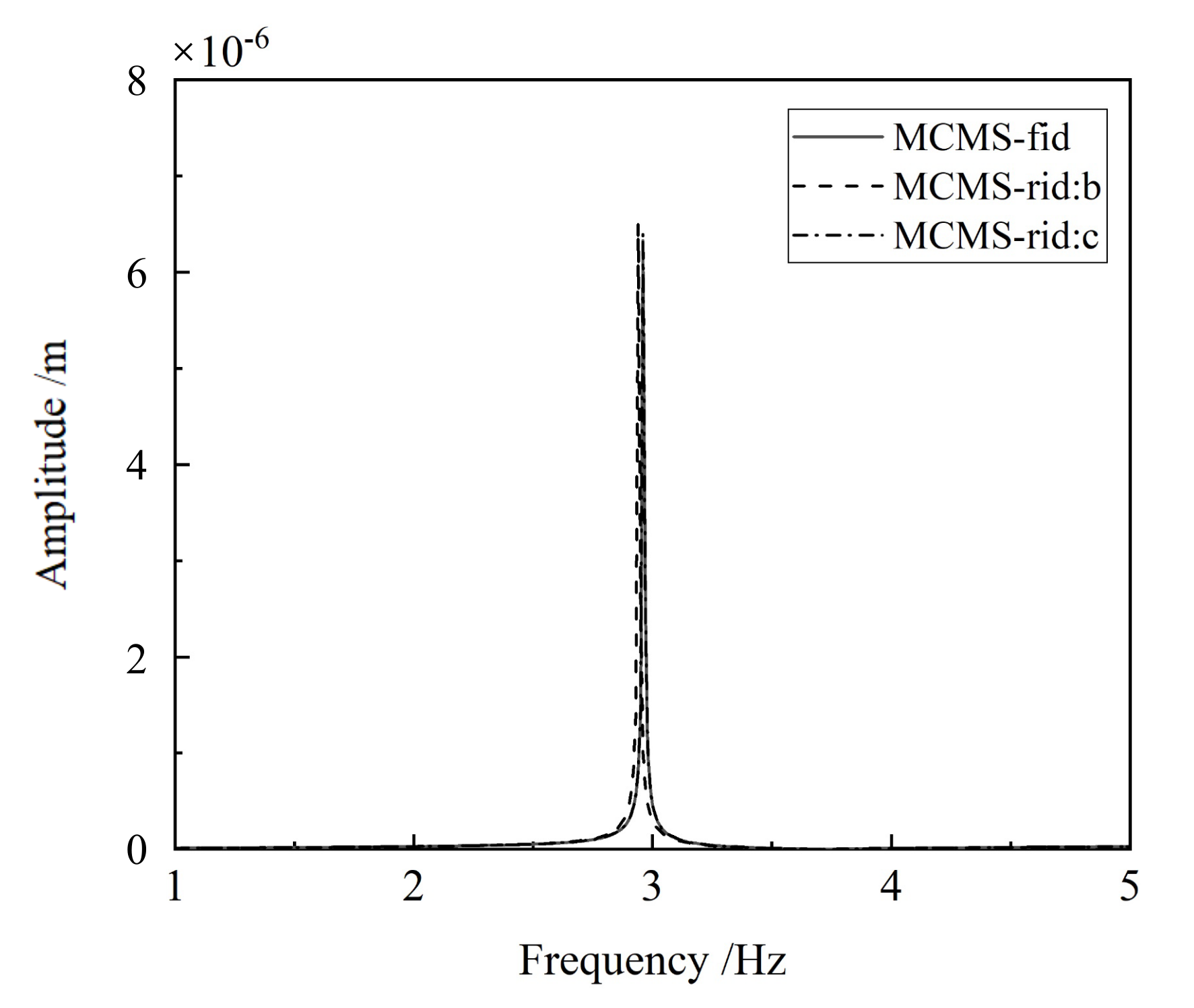
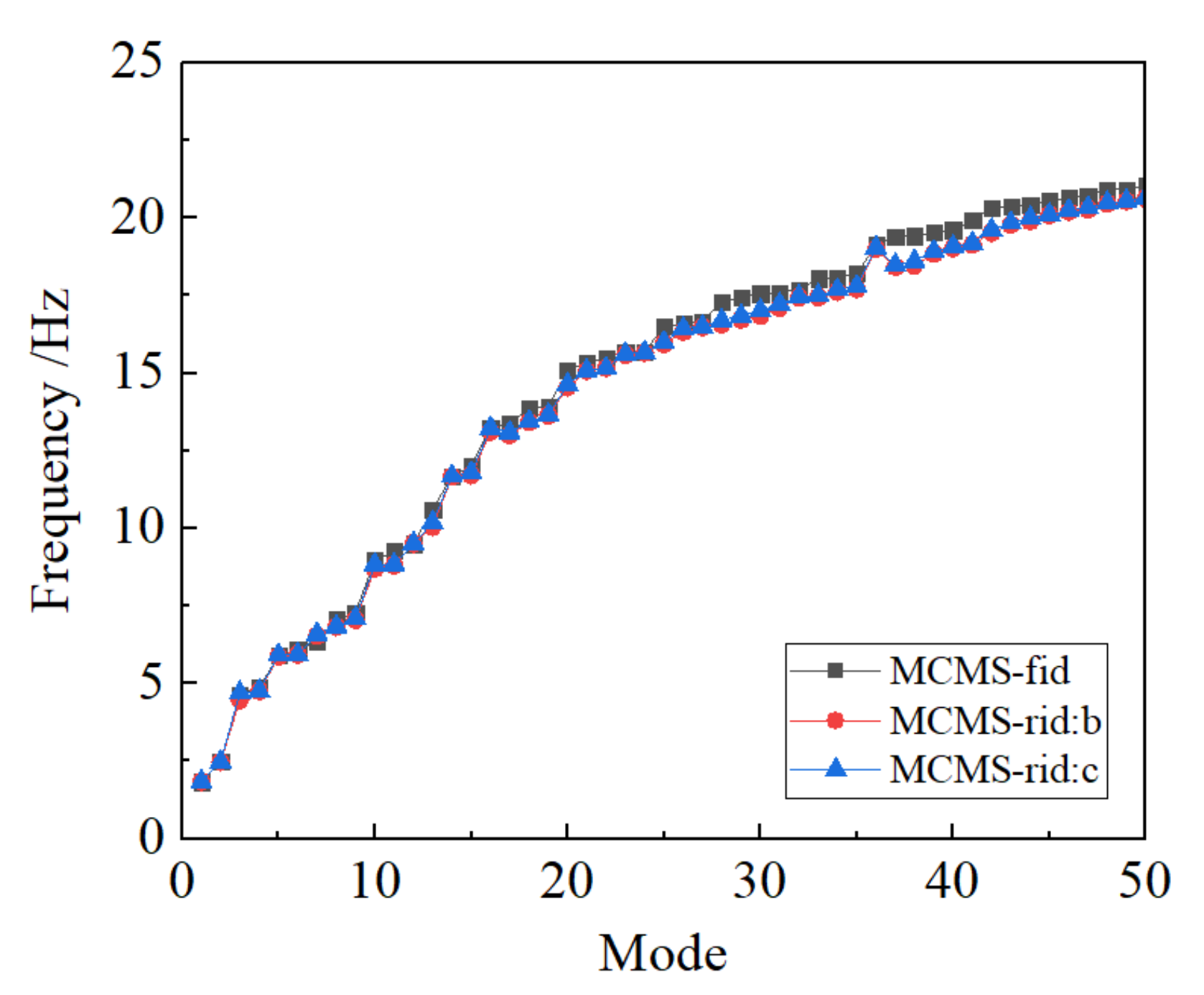
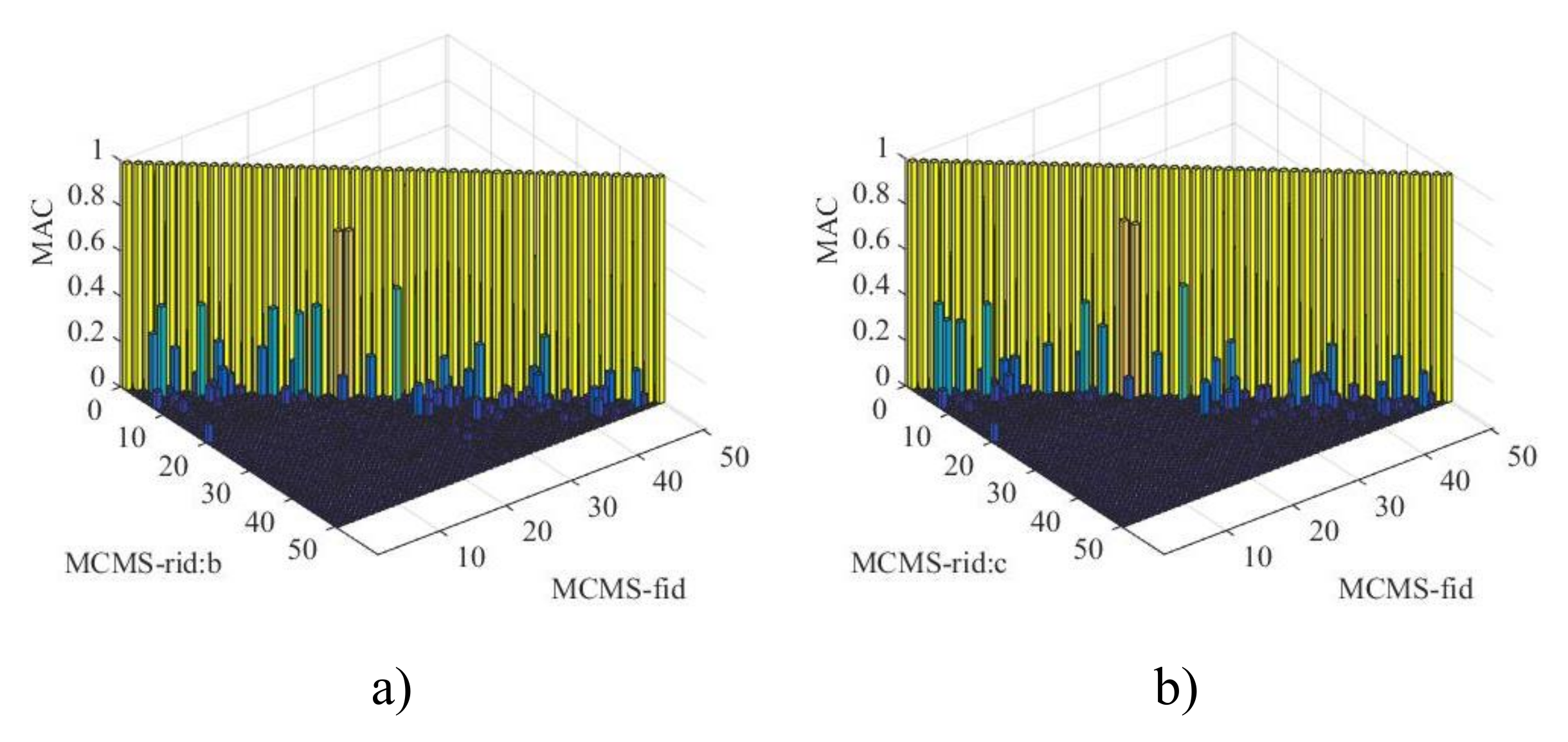
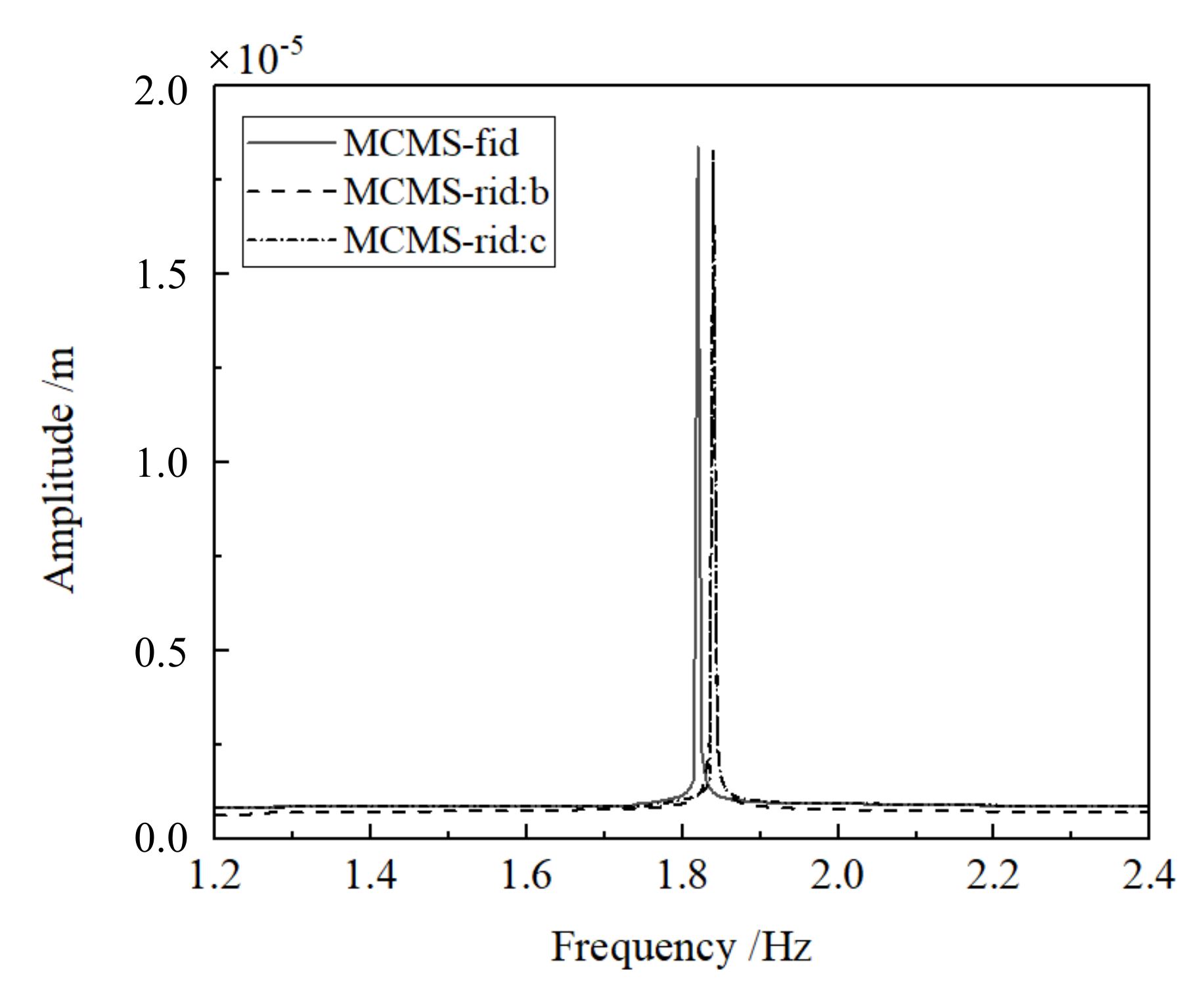
The first fifty natural frequencies and their relative errors between the MCMS-fid and MCMS-rid method are plotted in Figure 14 and Figure 15, respectively. It is illustrated that the values of errors are less than 5% and no upward trend of the relative errors occurs as the mode increases. The MAC between the modes by the MCMS-fid method and the MCMS-rid method is investigated as shown in Figure 16, and the unitary values on the main diagonal of the plot indicate a good matching of these two methods. The FRF comparisons are conducted by applying a harmonic excitation at excitation level of 1N in the X direction at the top of the dam, and the results for the first mode are plotted in Figure 17. All the results of relative errors, MAC and FRF verify the feasibility and validity of the MCMS-rid method when the FE model is huge and the substructures have different material properties. Meanwhile, similar conclusions can be drawn that the accuracy of the MCMS-rid method will be improved as the number of the IBNs is increasing and the sub-regions are evenly distributed and nearly square.

6. Conclusions

The CMS method is one of the well-developed modal order reduction technique that describes the whole structure with several independent components/substructures. Modal analysis are carried out in each component and then mode synthesis are done based on the displacement-coordination or/and force-equilibrium at the interfaces of substructures. As the internal DOFs are greatly reduced by the first coordinate transformation, the number of the coupling interface DOFs involved in mode synthesis will rule the following computational efficiency and accuracy. In this paper, we focus on reducing the coupling interface DOFs to solve the problems of docking difficulties and incomplete boundary conditions. The following conclusions may be drawn:
(a) Displacement and force interpolation functions of the coupling interface DOFs using nodal displacement interpolation formulations based on FEM are set up for the MCMS method. The corresponding interpolation transformation is done before mode synthesis, and only a small number of IBNs are kept so that the proposed method is very computationally efficient for solving eigenvalue problems.
(b) The numerical performance of the MCMS-rid method is demonstrated by three different examples, where different structural properties and FE model size are discussed properly. The results indicate that favourable accuracy with a least number of the retained DOFs involved in modal synthesis can be obtained when compared with other MCMS methods.
(c) The number and distribution of IBNs chosen for mode synthesis have significant influence on the numerical precision. It is noticed that the more the IBNs involved, the higher the calculation accuracy will be obtained. And when the IBNs uniformly distribute on the coupling interface, the accuracy is the best.
(d) The shape of sub-regions also greatly effects the computational accuracy. Dividing the interface with quadrangular interpolation sub-regions may receive a better accuracy than that with triangle ones. However, the triangle interpolation sub-regions show advantages when the coupling interface is irregular.

Author Contributions

Conceptualization, Y.T. and H.Q.; methodology, Y.T.; software, H.Q.; data curation, Y.T.; writing–original draft preparation, Y.T.; writing–review and editing, H.Q.; funding acquisition, Y.T. and H.Q. All authors have read and agreed to the published version of the manuscript.

Funding

This research was funded by “the National Key R & D Program of China (Grant No. 2017YFC0404900)”, “the National Natural Science Foundation of China (Grant No. 41904095 and 51979027)”, “the Open Fund of Key Laboratory of Geotechnical and Underground Engineering of Ministry of Education at Tongji University (Grant No. KLE-TJGE-B1804)”, “the State Key Laboratory of Mechanical Behavior and System Safety of Traffic Engineering Structures at Shijiazhuang Tiedao University (Grant No. ZZ2020-04)”, and “the Fundamental Research Funds for the Central Universities (Grant No. DUT19JC23/DUT19RC(4)020)”.

Conflicts of Interest

The authors declare no conflict of interest.

References

  1. Rixen, D.J. A dual Craig-Bampton method for dynamic substructuring. J. Comput. Appl. Math. 2004, 168, 383–391. [Google Scholar] [CrossRef]
  2. Cunedioglua, Y.; Mugana, A.; Akay, H. Frequency domain analysis of model order reduction techniques. Finite Elem. Anal. Des. 2006, 42, 367–403. [Google Scholar] [CrossRef]
  3. Klerk, D.D.; Rixen, D.J.; Voormeeren, S.N. General framework for dynamic substructuring: History, review, and classification of techniques. AAIA J. 2008, 46, 1169–1181. [Google Scholar] [CrossRef]
  4. David, A.; Charbel, F.; Carlberg, K.; Farhat, C. A method for interpolating on manifolds structural dynamics reduced-order models. Int. J. Numer. Methods Eng. 2009, 80, 1241–1258. [Google Scholar]
  5. David, A.; Charbel, F.; Carlberg, K.; Farhat, C. An online method for interpolating linear parametric reduced-order models. SIAM J. Sci. Comput. 2011, 33, 2169–2198. [Google Scholar]
  6. David, A.; Charbel, F.; Bernard, H. Special issue on model reduction. Int. J. Numer. Methods Eng. 2015, 102, 931–932. [Google Scholar]
  7. Kim, J.G.; Park, Y.J.; Lee, G.H.; Kim, D.N. A general model reduction with primal assembly in structural dynamics. Comput. Methods Appl. Mech. Eng. 2017, 324, 1–28. [Google Scholar] [CrossRef]
  8. Kim, S.M.; Kim, J.G.; Park, K.; Chae, S.W. A component mode selection method based on a consistent perturbation expansion of interface displacement. Comput. Methods Appl. Mech. Eng. 2018, 330, 578–597. [Google Scholar] [CrossRef]
  9. Hurty, W.C. Vibration of structure systems by component mode synthesis. J. Eng. Mech. Div. 1960, 86, 51–69. [Google Scholar]
  10. Hurty, W.C. Dynamic analysis of structural systems using component modes. AAIA J. 1965, 3, 678–685. [Google Scholar] [CrossRef]
  11. Bampoton, M.C.C.; Craig, R.R. Coupling of substructures for dynamic analysis. AAIA J. 1968, 6, 1313–1319. [Google Scholar]
  12. Hou, S.N. Review of modal synthesis techniques and new approach. Shock Vib. Bull. 1969, 40, 25–399. [Google Scholar]
  13. Benfield, W.A.; Hruda, R.F. Vibration analysis of structures by component mode substitution. AAIA J. 1971, 9, 1225–1261. [Google Scholar] [CrossRef]
  14. Gruber, F.M.; Rixen, D.J. Evaluation of Substructure Reduction Techniques with Fixed and Free Interfaces. Stroj Vestn J. Mech. E 2016, 62, 452–462. [Google Scholar] [CrossRef]
  15. Barbone, P.E.; Givoli, D.; Patlashenko, I. Optimal modal reduction of vibrating substructures. Int. J. Numer. Methods Eng. 2003, 57, 341–369. [Google Scholar] [CrossRef]
  16. Givoli, D.; Barbone, P.E.; Patlashenko, I. Which are the important modes of a subsystem? Int. J. Numer. Methods Eng. 2004, 59, 1657–1678. [Google Scholar] [CrossRef]
  17. Bai, Z.; Liao, B.S. Towards an optimal substructuring method for model reduction. Int. Workshop Appl. Parallel Comput. 2004, 3732, 276–285. [Google Scholar]
  18. Tayeb, S.; Givoli, D. Optimal modal reduction of dynamic subsystems: Extensions and improvements. Int. J. Numer. Methods Eng. 2011, 85, 1–30. [Google Scholar] [CrossRef]
  19. Park, K.C.; Kim, J.G.; Lee, P.S. A mode selection criterion based on flexibility approach in component mode synthesis. In Proceedings of the 53th AIAA/ASME/ASCE/AHS/ASC Structures, Structural Dynamics, and Materials Conference, Honolulu, HI, USA, 23–26 April 2012; pp. 1883–2012. [Google Scholar]
  20. Kim, J.G.; Lee, P.S.; Park, K.C. A mode selection algorithm for the flexibility based component mode synthesis. In Proceedings of the 5th International Conference on Computational Methods in Structural Dynamics and Earthquake Engineering, Crete Island, Greece, 25–27 May 2015; pp. 3162–3171. [Google Scholar]
  21. Kim, S.M.; Kim, J.G.; Chae, S.W.; Park, K.C. Evaluating mode selection methods for component mode synthesis. AIAA J. 2016, 54, 2856–2863. [Google Scholar] [CrossRef]
  22. Roettgen, D.; Seeger, B.; Tai, W.C.; Baek, S.; Dossogne, T.; Allen, M.; Kuether, R.; Brake, M.R.W.; Mayes, R. A Comparison of Reduced Order Modeling Techniques Used in Dynamic Substructuring. Conf. Proc. Soc. Exp. Mech. Ser. 2016, 4, 511–528. [Google Scholar]
  23. Rubin, S. Improved component-mode representation for structural dynamic analysis. AIAA J. 1975, 13, 995–1006. [Google Scholar] [CrossRef]
  24. Majed, A.; Henkel, E.E. Improved method of mixed-boundary component-mode representation for structural dynamic analysis. J. Spacecr. Rocket. 2005, 42, 825–831. [Google Scholar] [CrossRef]
  25. Petrov, E. A high-accuracy model reduction for analysis of nonlinear vibrations in structures with contact interfaces. J. Eng. Gas. Turbines Power 2011, 133, 102503. [Google Scholar] [CrossRef]
  26. Kim, J.G.; Boo, S.H.; Lee, P.S. An enhanced AMLS method and its performance. Comput. Methods Appl. Mech. Eng. 2015, 287, 90–111. [Google Scholar] [CrossRef]
  27. Gruber, F.E.; Gille, M.; Rixen, D.J. A strategy to stabilize the transient analysis and increase the approximation accuracy of dual Craig-Bampton reduced systems. Finite Elem. Anal. Des. 2019, 160, 32–45. [Google Scholar] [CrossRef]
  28. Lou, M.L. Introduction of the component mode synthesis. In Substructue Methods for Dynamic Analysis of Structures; Tongji University Press: Shanghai, China, 1997; pp. 71–103. [Google Scholar]
  29. Becker, J.; Gau, L. CMS Methods for Efficient Damping Prediction for Structures with Friction. In Proceedings of the IMAC-XXVI, Orlando, FL, USA, 9–12 February 2009; pp. 3–13. [Google Scholar]
  30. Gaul, L.; Becker, J. Damping prediction of structures with bolted joints. Shock Vib. 2010, 17, 359–371. [Google Scholar] [CrossRef]
  31. Lee, J. Maenghyo ChobAn interpolation-based parametric reduced order model combined with component mode synthesis. Comput. Methods Appl. Mech. Eng. 2018, 319, 258–286. [Google Scholar] [CrossRef]
  32. Park, K.C.; Park, Y.H. Partitioned component mode synthesis via a flexibility approach. AIAA J. 2004, 42, 1236–1245. [Google Scholar] [CrossRef]
  33. Markovic, D.; Park, K.C.; Ibrahimbegovic, A. Reduction of substructure interface degrees of freedom in flexibility-based component mode synthesis. Int. J. Numer. Methods Eng. 2007, 70, 163–180. [Google Scholar] [CrossRef]
  34. Gruber, F.M.; Burchner, T.L.; Rixen, D.J. Dual Craig-Bampton Method with Reduction of Interface Coordinates. Conf. Proc. Soc. Exp. Mech. Ser. 2017, 4, 143–163. [Google Scholar]
  35. Battiatoa, G.; Firronea, C.M.; Berrutia, T.M.; Epureanu, B.I. Reduction and coupling of substructures via Gram–Schmidt Interface modes. Comput. Methods Appl. Mech. Eng. 2018, 336, 187–212. [Google Scholar] [CrossRef]
  36. Jeong, G.; Song, Y.; Youn, S.; Park, K.C. A new approach for nonmatching interface construction by the method of localized Lagrange multipliers. Comput. Methods Appl. Mech. Eng. 2020, 361, 112728. [Google Scholar] [CrossRef]
  37. Lou, M.L.; Yin, L. Degrees of freedom reduction technique for interface of constrained substructure based on node displacement interpolation. Eng. Mech. 2012, 29, 25–29, 36. [Google Scholar]
  38. Lou, M.L.; Tang, Y.; Yin, L. Degrees of freedom reduction technique for free interface substructure based on nodal force interpolation. J. Tongji Univ. (Nat. Sci.) 2015, 43, 662–667. [Google Scholar]
  39. Guyan, R.J. Reduction of stiffness and mass matrices. AIAA J. 1965, 3, 380. [Google Scholar] [CrossRef]
  40. Yin, X.; Dong, M.; Huang, H. The revised mode method for mix-interface mode synthesis method. Comput. Struct. Mech. Appl. 1997, 4, 89–94. [Google Scholar]
  41. Lou, M.L. Mix-interface component mode synthesis. In Substructue Methods for Dynamic Analysis of Structures; Tongji University Press: Shanghai, China, 1997; pp. 107–165. [Google Scholar]
  42. Bathe, K.J. Finite Element Procedures; Prentice Hall: Upper Saddle River, NJ, USA, 1996. [Google Scholar]
  43. Lou, M.L.; Zhao, Y.L. Substructure method for dynamic analysis of dam-rock foundation interaction. J. Vib. Eng. 1994, 7, 161–166. [Google Scholar]
Figure 1. Scheme of a mixed-substructure.
Applsci 10 02759 g001
Figure 2. The finite element mesh of the interface and the local coordinate of sub-region. (a) global coordinate system; (b) local coordinate system.
Applsci 10 02759 g002
Figure 3. Finite element model of the beam with two ends fixed.
Applsci 10 02759 g003
Figure 4. The coupling interface and interpolating schemes. (a) the coupling interface; (b) scheme with 9 interpolation basic nodes; (c) scheme with 4 interpolation basic nodes; (d) scheme with 10 interpolation basic nodes.
Applsci 10 02759 g004
Figure 5. The first four mode shapes of the beam. (a) 1st mode in x-direction ( f 1 = 39.10 Hz); (b) 1st mode in y-direction ( f 2 = 56.62 Hz); (c) 2nd mode in x-direction ( f 3 = 104.63 Hz); (d) 2nd mode in y-direction ( f 4 = 146.16 Hz).
Applsci 10 02759 g005
Figure 6. Modal assurance criterion between the modes by the MCMS-fid method and MCMS-rid method different interpolation schemes. (a) MCMS-rid:b vs. MCMS-fid; (b) MCMS-rid:c vs. MCMS-fid; (c) MCMS-rid:d vs. MCMS-fid.
Applsci 10 02759 g006
Figure 7. Frequency response functions of the beam by the MCMS-fid method and MCMS-rid method with different interpolation schemes for the first mode.
Applsci 10 02759 g007
Figure 8. Finite element model of elastic body.
Applsci 10 02759 g008
Figure 9. The coupling interface and interpolating schemes. (a) the coupling interface; (b) scheme with triangular interpolation sub-regions; (c) scheme with quadrangle and triangular interpolation sub-regions.
Applsci 10 02759 g009
Figure 10. Modal assurance criterion between the modes by the MCMS-fid method and MCMS-rid method different interpolation schemes. (a) MCMS-rid:b vs. MCMS-fid; (b) MCMS-rid:c vs. MCMS-fid.
Applsci 10 02759 g010
Figure 11. Frequency response functions of the beam by the FE model, MCMS-fid and MCMS-rids with different interpolation schemes for the first mode.
Applsci 10 02759 g011
Figure 12. Finite element model and dimensions of the simplified dam-foundation system.
Applsci 10 02759 g012
Figure 13. The coupling interface and interpolating schemes. (a) the coupling interface; (b) scheme with 6 interpolation basic nodes; (c) scheme with 12 interpolation basic nodes.
Applsci 10 02759 g013
Figure 14. The first fifty natural frequencies (Hz) by the MCMS-fid and MCMS-rid methods.
Applsci 10 02759 g014
Figure 15. Relative errors (%) of the first fifty natural frequencies for Scheme b and c.
Applsci 10 02759 g015
Figure 16. Modal assurance criterion between the modes by the MCMS-fid method and MCMS-rid method different interpolation schemes. (a) MCMS-rid:b vs. MCMS-fid; (b) MCMS-rid:c vs. MCMS-fid.
Applsci 10 02759 g016
Figure 17. Frequency response functions of the beam by FE model, MCMS-fid and MCMS-rids with different interpolation schemes for the first mode.
Applsci 10 02759 g017
Table 1. The first eight natural frequencies of the beam f (Hz) and relative error e (%).
MethodModeDOFs
12345678
FEM39.1056.62104.63146.16157.97197.94266.41290.812175
B-H41.3559.5489.13126.89162.43231.80306.17309.7515
(5.74)(5.16)(14.81)(13.18)(2.82)(17.11)(14.92)(6.51)
BHC39.5156.4485.77121.06159.43224.84293.84299.621500
(1.04)(0.31)(18.03)(17.17)(0.92)(13.59)(10.09)(3.03)
MCMS-fid39.4756.3695.67134.88159.02214.40284.67298.65165
(0.94)(0.46)(8.56)(7.72)(0.66)(8.32)(6.85)(2.70)
MCMS-rid39.8956.2895.05133.63159.97217.61279.00299.9069
(2.02)(0.60)(9.16)(8.57)(1.26)(9.94)(4.72)(3.13)
Table 2. The first eight natural frequencies of the beam f (Hz) and relative error e (%).
SchemeModeDOFs
12345678
a39.4756.3695.67134.88159.02214.40284.67298.65165
b39.8956.2895.05133.63159.97217.61279.00299.9069
(1.06)(0.14)(0.65)(0.93)(0.60)(1.50)(1.99)(0.42)
c42.2358.2288.79132.56165.71226.48293.96307.5239
(6.99)(3.30)(7.19)(1.72)(4.21)(5.63)(3.26)(2.97)
d40.0456.0596.35134.23160.22218.18281.08297.3480
(1.44)(0.55)(0.71)(0.48)(0.75)(1.76)(1.26)(0.44)
Table 3. The first eight natural frequencies of the beam (Hz) and relative error (%).
SchemeModeDOFs
12345678
a2.963.735.135.259.199.4210.2810.75210
b2.943.775.335.279.669.6810.7611.16126
(0.59)(1.12)(3.90)(0.45)(5.11)(2.76)(4.68)(3.83)
c2.963.565.355.269.449.5910.6711.01126
(0.08)(0.14)(4.32)(0.14)(2.77)(1.83)(3.80)(2.46)
Table 4. Material properties of the system.
Density (kg/m 3 )Elastic Modulus (GPa)Passion Ratio
Dam2450200.25
Foundation2700120.17
Table 5. Features of the dam and foundation FE model
FE Model# Node# Element# DOF
Dam4224381012,672
Foundation316827287792
Interface176150528
Table 6. Comparison of CPU time (s).
CPU FEM CPU MCMS fid CPU MCMS rid : b CPU MCMS rid : c CPU MCMS fid CPU FEM CPU MCMS rid : b CPU FEM CPU MCMS rid : c CPU FEM
780.4659.4630.9132.370.07620.03960.0414