Design and Research of a Three-Phase AC Magnetic Separator for Coal Desulfurization and Ash Reduction

Abstract
:1. Introduction
2. Basic Structure and Operating Principle of the Three-Phase AC Magnetic Separator
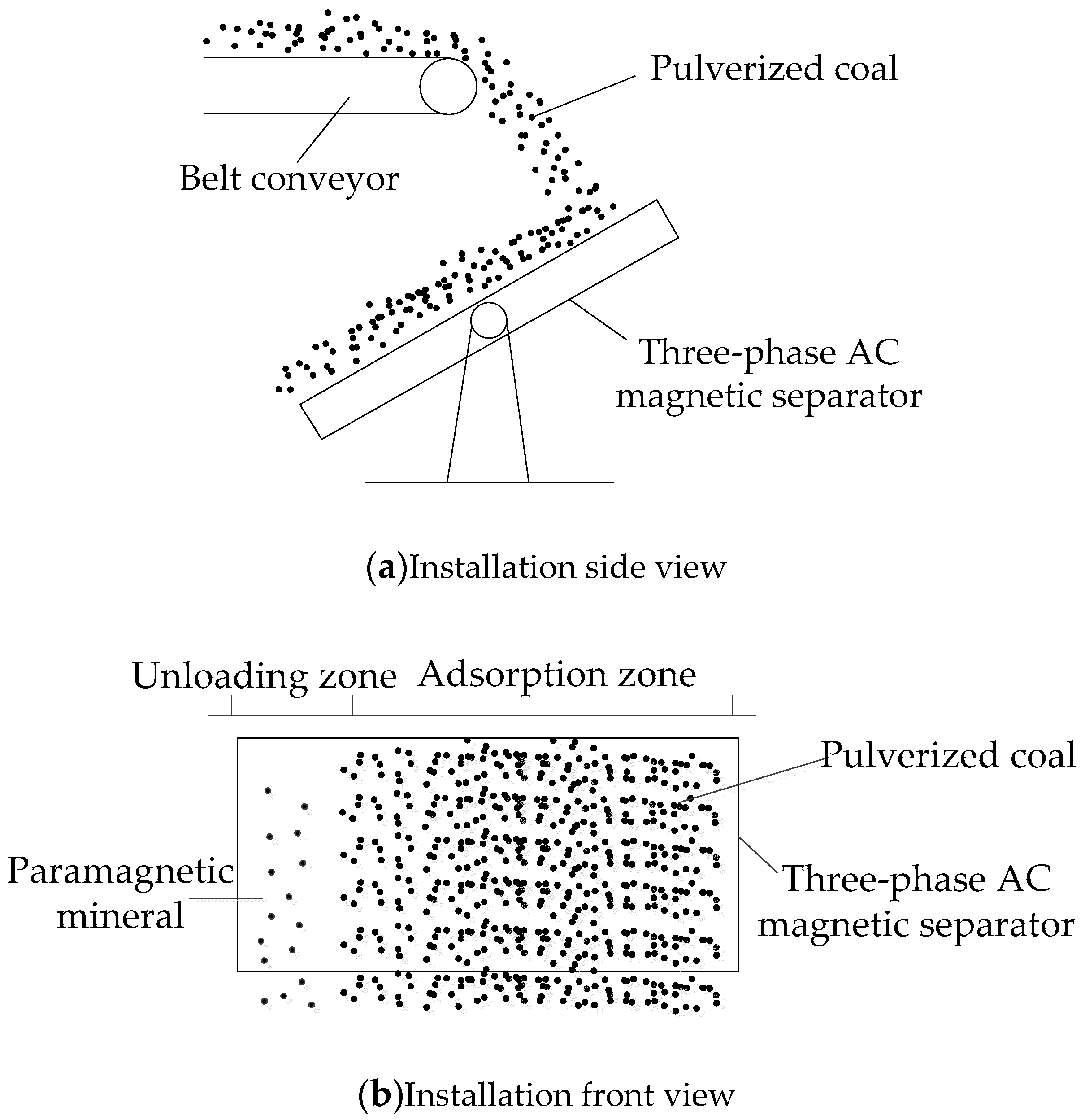
2.1. Basic Structure of the Three-Phase AC Magnetic Separator
2.2. The Working Principle of the Three-Phase AC Magnetic Separator
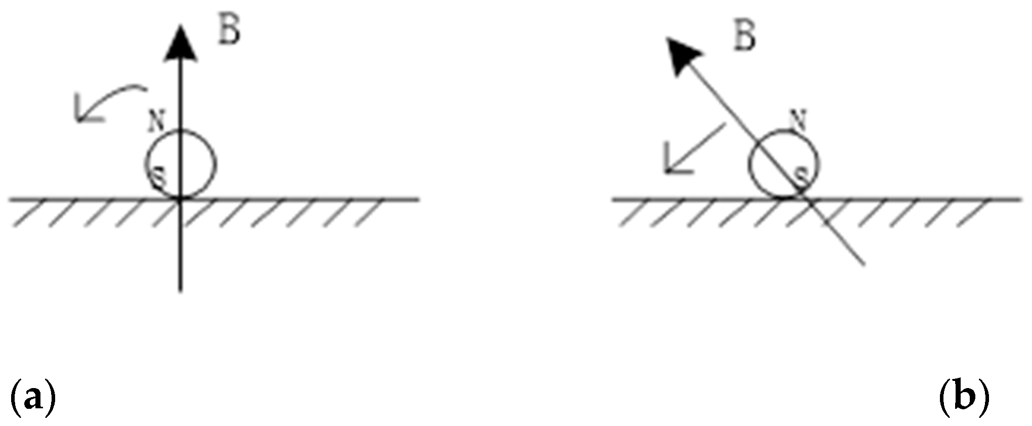
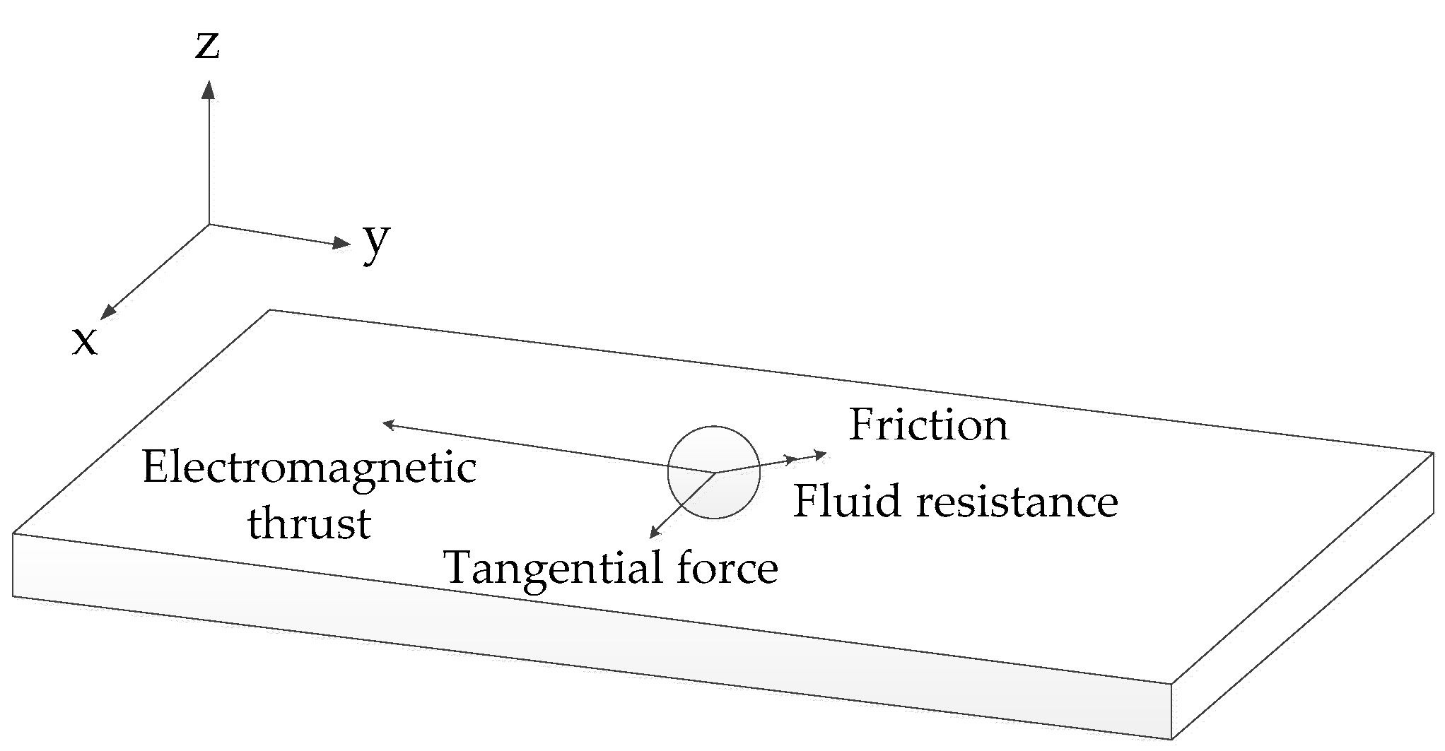
2.3. Force Analysis of Magnetic Particles on the Magnetic Separator
3. Structural Optimization and Characteristic Analysis of the Three-Phase AC Magnetic Separator
3.1. Structural Optimization of the Three-Phase AC Magnetic Separator
3.1.1. Tooth and Slot Size Optimization of the Three-Phase AC Magnetic Separator
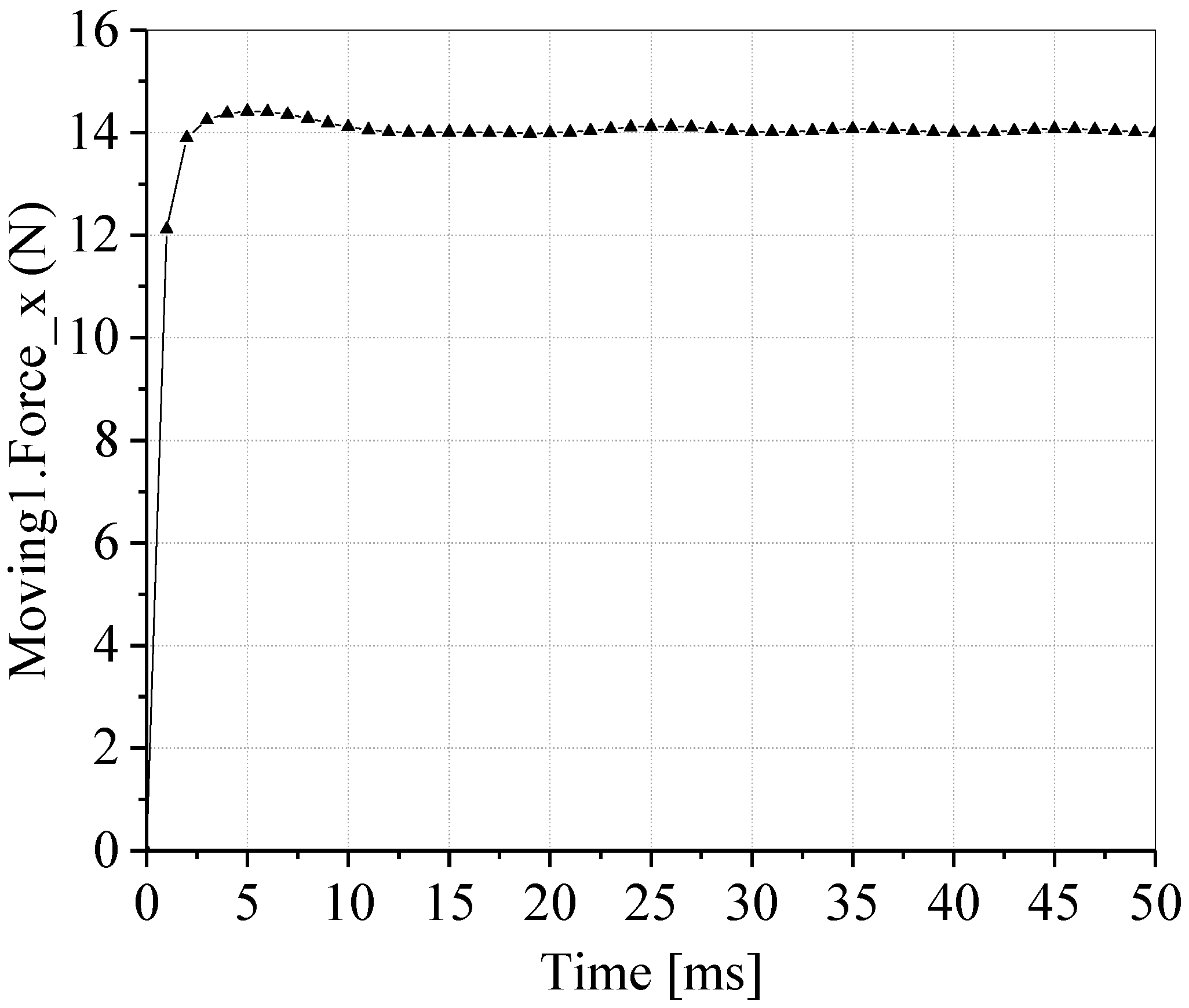
3.1.2. Comparative Analysis of a Single-Sided and Double-Sided Three-Phase AC Magnetic Separator
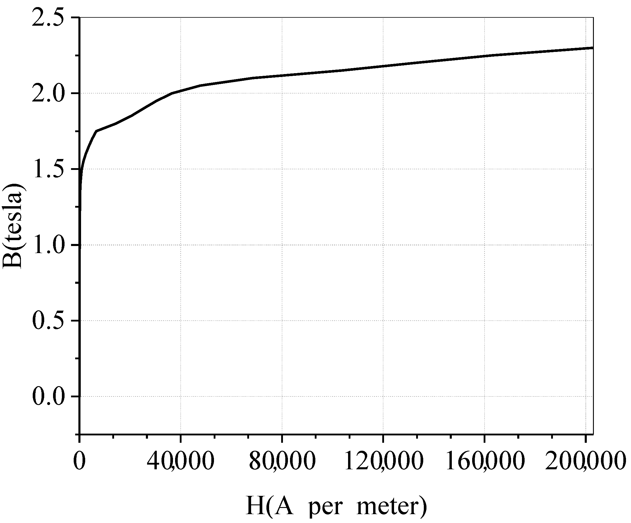
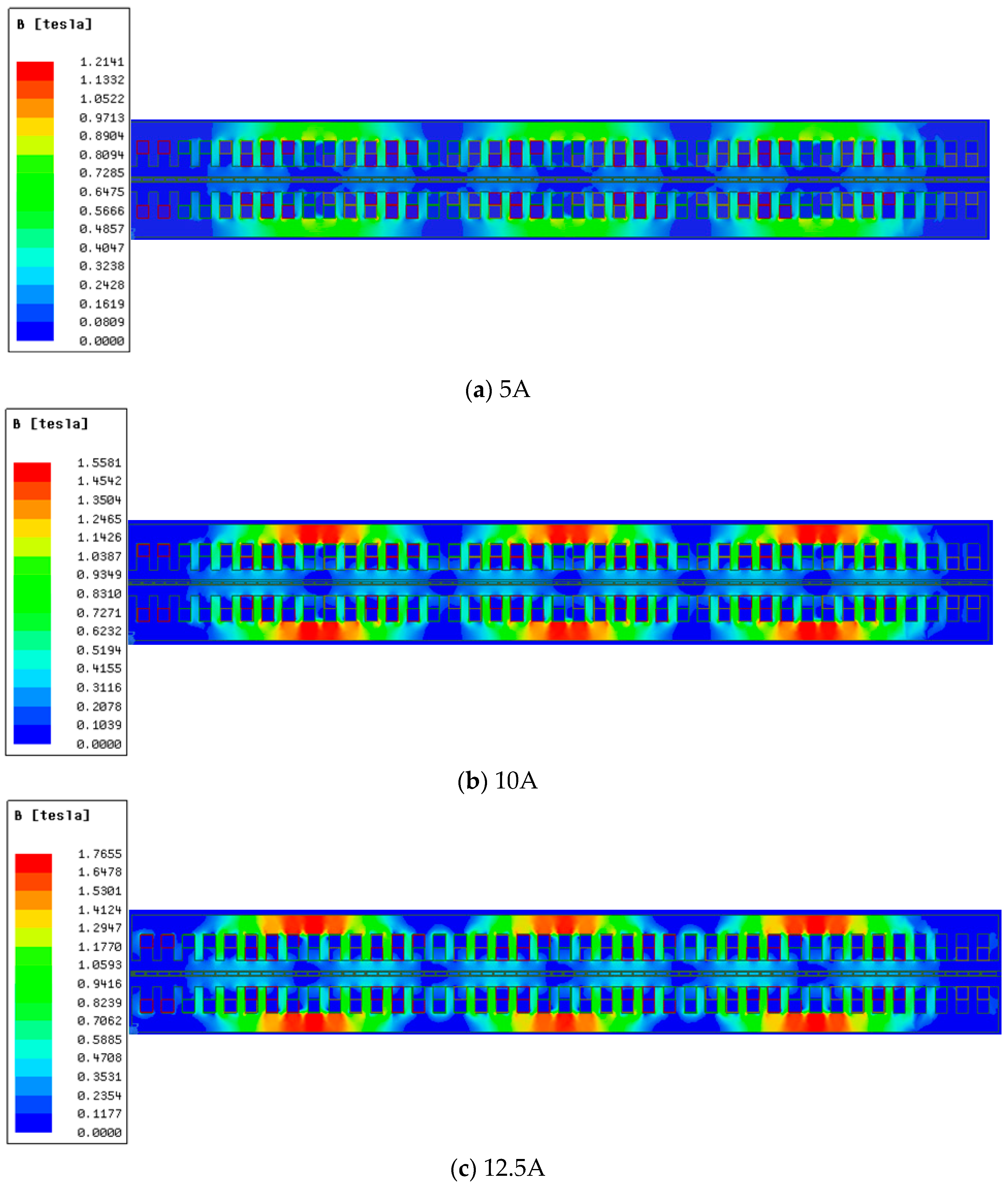
3.2. Magnetic Saturation Analysis
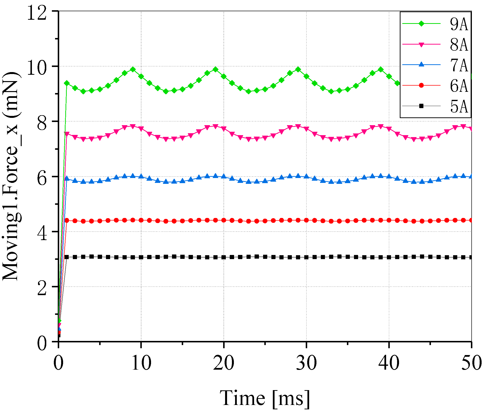
3.3. Effects of Current on Electromagnetic Thrust
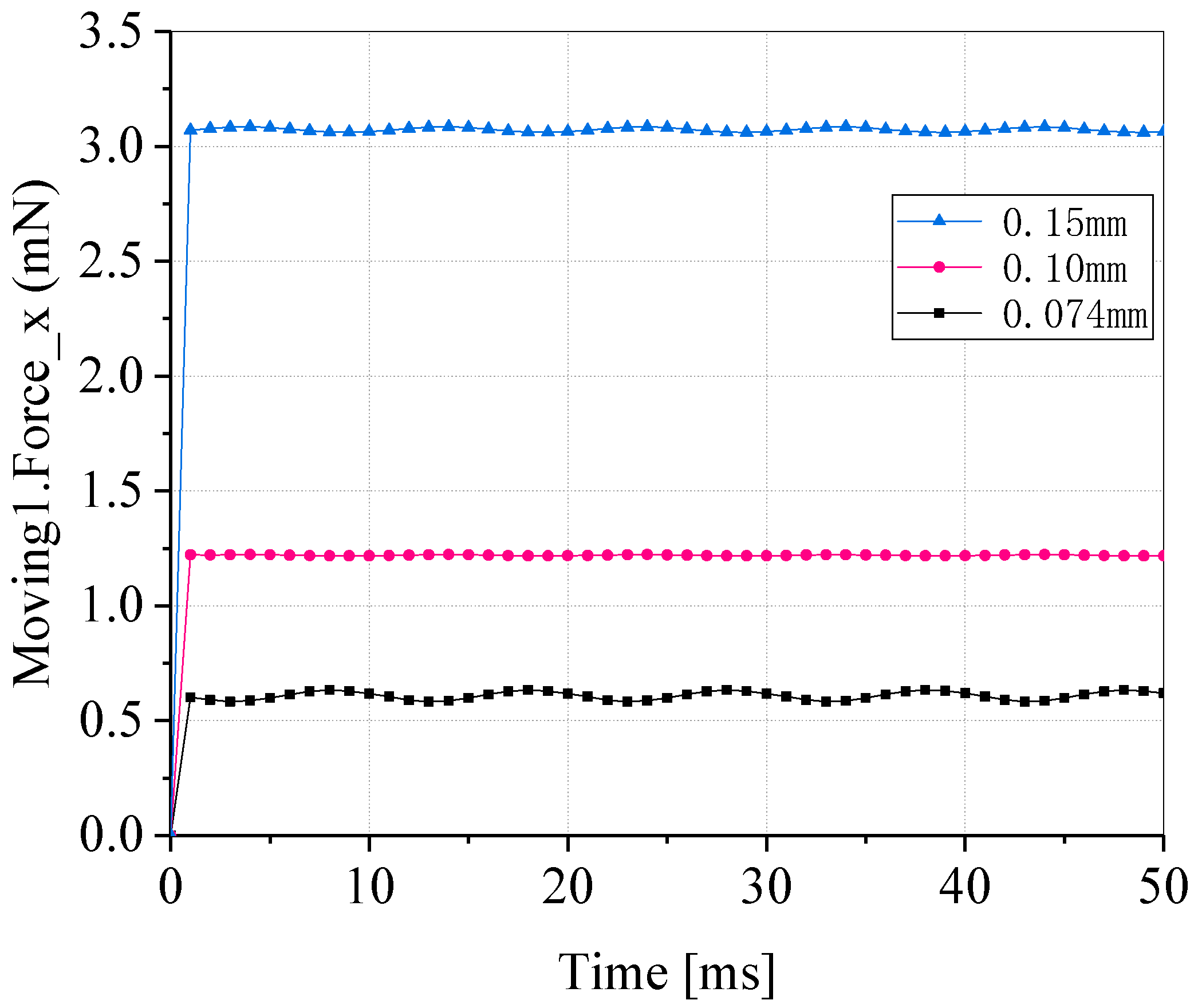
3.4. Effects of Particle Size of Magnetic Particles
3.5. Impacts of Mounting Tilt Angle
4. Conclusions
- (1)
- After structural optimization, the electromagnetic thrust of the three-phase AC magnetic separator is 8 times that of the original;
- (2)
- When the three-phase current is less than 12.5A, the magnetic density of the three-phase AC magnetic separator is lower than the saturation magnetic density of the silicon steel sheet, which can be considered as a linear model;
- (3)
- As the current increases, the electromagnetic force tends to increase. Therefore, in actual situations, when the magnetic particles are weakly magnetic, a larger current can be used; when the magnetic particles are strongly magnetic, a smaller current can be used, so as to achieve the effect of energy saving. The movement speed of the magnetic particles can be changed by adjusting the magnitude of the current to achieve the purpose of magnetic desulfurization;
- (4)
- When the three-phase current is 5A, the larger the particle size of the magnetic particles, the smaller the acceleration;
- (5)
- As the magnetic particle size is small, the electromagnetic force is large, and the influence of gravity is small, the acceleration of the magnetic particle does not change obviously when the installation angle of the three-phase AC magnetic separator increases. Therefore, in the sorting process, the falling speed of the diamagnetic particles can be adjusted by altering the inclination angle of the three-phase AC magnetic separator.
Author Contributions
Funding
Acknowledgments
Conflicts of Interest
References
- Chen, Y.; Cao, M.; Ma, C. Review of Coal-fired Electrification and Magnetic Separation Desulfurization Technology. Appl. Sci. 2019, 9, 1158. [Google Scholar] [CrossRef] [Green Version]
- Brown, D.K. Electrostatic Pyrite Ash and Toxic Mineral Separator. U.S. Patent 5637122, 10 June 1997. [Google Scholar]
- Jiao, H.; Cui, J.; Chen, Q. Review on dry desulphurization and ash reduction technology of pulverized coal before combustion. Coal Qual. Technol. 2007, 2, 43–45,47. [Google Scholar] [CrossRef]
- Tao, D.; Sobhy, A.; Li, Q.; Zhao, Y. Dry cleaning of pulverized coal using a novel rotary triboelectrostatic separator (RTS). Int. J. Coal Prep. Util. 2011, 31, 187–202. [Google Scholar] [CrossRef]
- Huang, G.; Luo, S.; Zhou, Y.; Ma, Y.; Yi, Y. Triboelectric separation of pulverized coal. Coal Technol. 2015, 34, 315–317. [Google Scholar] [CrossRef]
- Song, A.; Tao, Y.; Xian, Y.; Zhang, X.; Ding, Q. Experimental study on desulfurization and ash reduction of micro pulverized coal by surface modification and enhanced rotary friction electric separation. China Coal 2015, 12, 79–85. [Google Scholar] [CrossRef]
- Zhang, W.C.; Tao, Y.; Song, A.; Xian, Y.S.; Man, Z.P.; Xue, Y.W. Experimental study on dust reduction by rotating friction electric separation of micro-pulverized coal. Coal Sci. Technol. 2017, 45, 196–200. [Google Scholar] [CrossRef]
- Feng, D.; Sun, Z. The present situation and Progress of permanent Magnet Separator. Ore Dress. Foreign Metals 1992, 12, 1–5. [Google Scholar]
- Xiong, D.; Liu, J. New Progress of Slon pulsation and Vibration High gradient Magnetic Separator. Met. Mine 2006, 361, 4–7. [Google Scholar] [CrossRef]
- Liu, X.; Chen, J. Development of a new Slon- 1000 dry vibration high gradient magnetic separator. Non Metal. Min. 2006, 29, 32–34. [Google Scholar] [CrossRef]
- Lindner, J.; Nirschl, H. A hybrid method for combining High-Gradient Magnetic Separation and centrifugation for a continuous process. Sep. Purif. Technol. 2014, 131, 27–34. [Google Scholar] [CrossRef]
- Cao, Z.; Li, W.; Qian, S. Development and Application of New Strong Magnetic Separation Combination Equipment. Metal Mine 2016, 12, 122–125. [Google Scholar] [CrossRef]
- Zhang, B.; Zhao, Y.; Zhou, C.; Duan, C. Fine Coal Desulfurization by Magnetic Separation and the Behavior of Sulfur Component Response in Microwave Energy Pretreatment. Energy Fuels 2015, 29, 1243–1248. [Google Scholar] [CrossRef]
- Zhang, B.; Fan, X.; Zhao, Y.; Cai, L. Desulfurization of microwave pretreated fine coal by magnetic separation. Part. Sci. Technol. 2018, 36, 600–608. [Google Scholar] [CrossRef]
- Zhang, B.; Zhu, G.; Sun, Z.; Yan, G.; Yao, H. Fine coal desulfurization and modeling based on high-gradient magnetic separation by microwave energy. Fuel 2018, 217, 434–443. [Google Scholar] [CrossRef]
- Ye, Y. Principle and Application of Linear Motor; China Machine Press: Beijing, China, 2000; ISBN 7-111-08050-5. [Google Scholar]
- Gu, J.; Chen, W.; Lei, J. Three-phase AC magnetic separator. Metall. Equip. 1989, 4, 14–17. [Google Scholar]
- Zhang, Y.; Shi, C.; Ma, J.; Zhang, Q. Pulverized Coal Magnetic Separation Purification Technology; Chemical Industry Press: Beijing, China, 2013; ISBN 7122165957. [Google Scholar]


| Parameter | Numerical Value | Parameter | Numerical Value |
|---|---|---|---|
| Total length Ls/mm | 486 | Total width Ws/mm | 84 |
| Total height Hs/mm | 50 | Slot width Wss/mm | 6.8 |
| Slot depth Hss/mm | 35 | Tooth width Wsp/mm | 4.87 |
| Slot Width Wss/mm | Slot Depth Hss/mm | Electromagnetic Thrust/N |
|---|---|---|
| 9.43 | 20.22 | 3.56 |
| 9.27 | 23.74 | 3.53 |
| 9.57 | 20.17 | 3.52 |
| 9.21 | 22.12 | 3.51 |
| 9.88 | 23.75 | 3.54 |
| Original Parameter | Optimized Simultaneously | Compared | |
|---|---|---|---|
| Slot width Wss/mm | 6.8 | 9.43 | - |
| Slot depth Hss/mm | 35 | 20.22 | - |
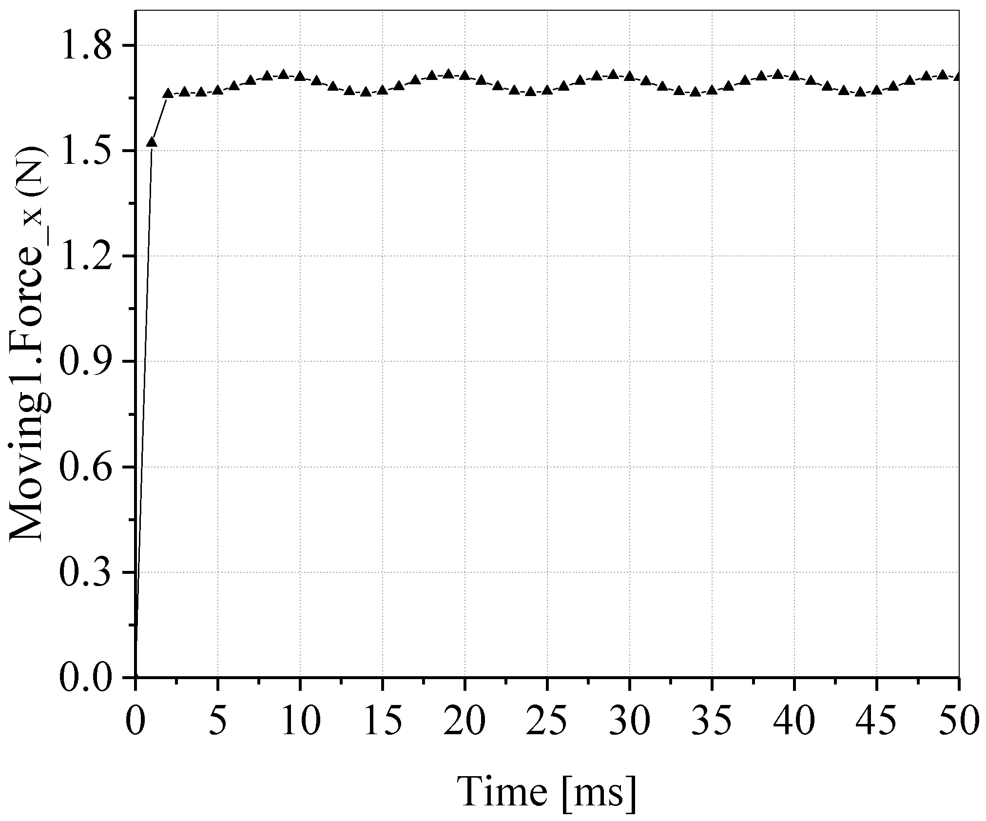
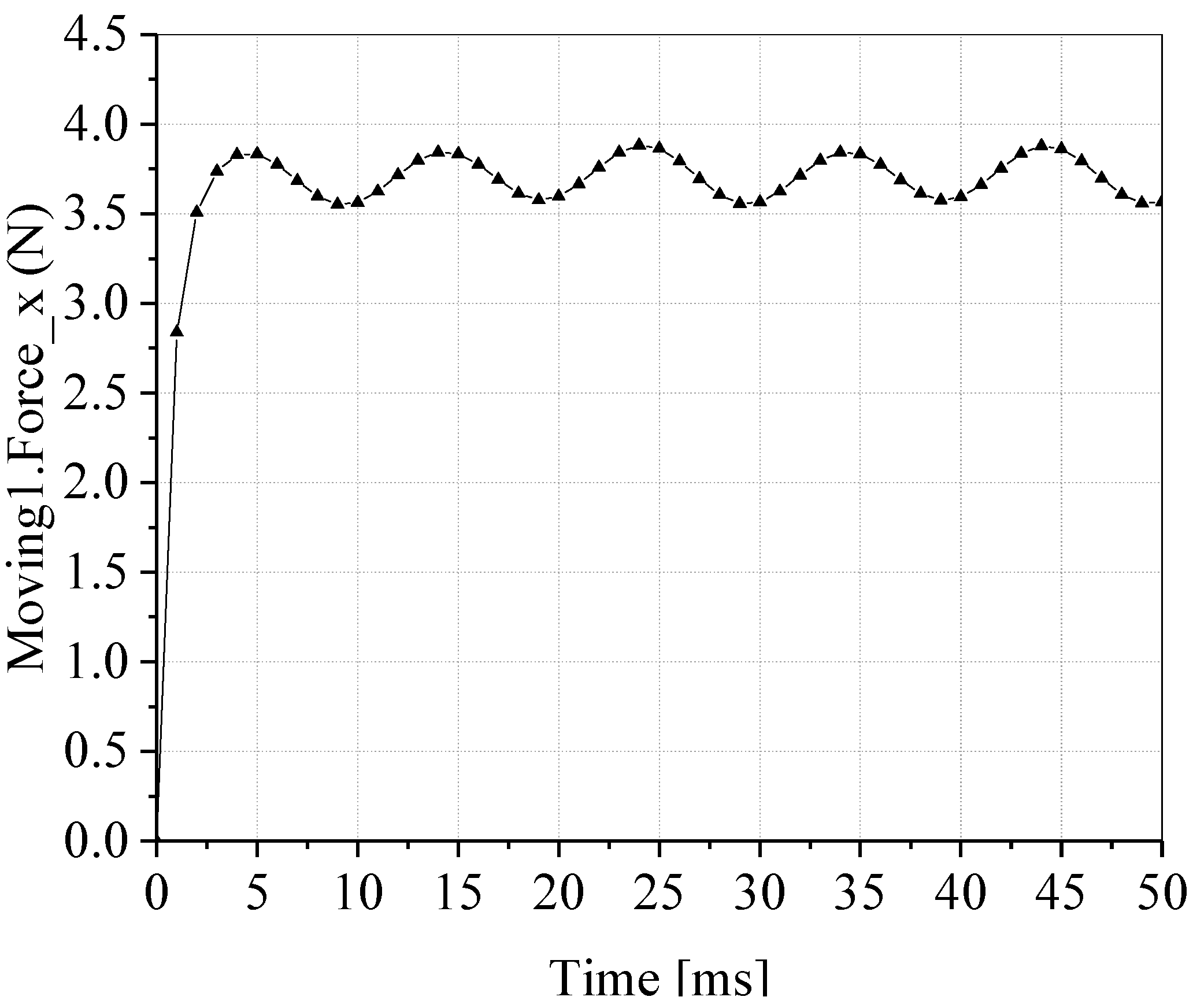
| Electromagnetic thrust Fx/N | 1.66 | 3.56 | 114% |
| Electromagnetic suction Fy/N | 0.35 | 0.67 | 91% |
| The Size of Granule | The Force the Particle Receives | |||||
|---|---|---|---|---|---|---|
| Electromagnetic Thrust/N | Electromagnetic Pull/N | Friction /N | Resistance | Joint Force /N | Acceleration /m·s−2 | |
| 0.15 mm | 3.0447 × 10⁻³ | 1.1914 × 10⁻⁴ | 9.5981 × 10⁻⁴ | 1.0122 × 10⁻⁷ | 2.0848 × 10⁻³ | 4.4555 |
| The Size of Particle | Electromagnetic Thrust/N | Electromagnetic Pull/N | Friction/N | Joint Force /N | Acceleration /m·s−2 | |
|---|---|---|---|---|---|---|
| 0.074 mm | 0.6024 × 10⁻³ | 4.6528 × 10⁻⁵ | 1.2167 × 10⁻⁴ | 4.9914 × 10⁻⁸ | 4.8068 × 10⁻⁴ | 8.5561 |
| 0.10 mm | 1.2075 × 10⁻³ | 1.4152 × 10⁻⁴ | 3.0558 × 10⁻⁴ | 6.7481 × 10⁻⁸ | 9.0185 × 10⁻⁴ | 6.5049 |
| 0.15 mm | 3.0447 × 10⁻³ | 1.1914 × 10⁻⁴ | 9.5981 × 10⁻⁴ | 1.0122 × 10⁻⁷ | 2.0848 × 10⁻³ | 4.4555 |
| Installation Angle | The Size of Particle | ||
|---|---|---|---|
| 0.074 mm | 0.10 mm | 0.15 mm | |
| 10° | 1.71134 × 10⁻⁶ | 4.2232 × 10⁻⁶ | 1.4253 × 10⁻⁵ |
| 30° | 5.13396 × 10⁻⁶ | 1.2669 × 10⁻⁵ | 4.2759 × 10⁻⁵ |
| 60° | 1.02675 × 10⁻⁵ | 2.5338 × 10⁻⁵ | 8.5515 × 10⁻⁵ |
| Installation Angle | The Size of Particle | ||
|---|---|---|---|
| 0.074 mm | 0.10 mm | 0.15 mm | |
| 10° | 5.6180 × 10⁻⁴ | 1.3864 × 10⁻³ | 4.6791 × 10⁻³ |
| 30° | 5.6178 × 10⁻⁴ | 1.3863 × 10⁻³ | 4.6789 × 10⁻³ |
| 60° | 5.6171 × 10⁻⁴ | 1.3863 × 10⁻³ | 4.6783 × 10⁻³ |
| The Size of Particle | The Force on the Particle | ||||||
|---|---|---|---|---|---|---|---|
| Electromagnetic Thrust/N | Electromagnetic Pull/N | Friction/N | Fluid Resistance | Resultant Force/N | Acceleration/m·s−2 | ||
| 0.074 mm | 0.6024 × 10⁻³ | 4.6528 × 10⁻⁵ | 1.2167 × 10⁻⁴ | 4.9914 × 10⁻⁸ | 4.8068 × 10⁻⁴ | 8.5561 | |
| 1.2166 × 10⁻⁴ | 4.8071 × 10⁻⁴ | 8.5566 | |||||
| 1.2165 × 10⁻⁴ | 4.8079 × 10⁻⁴ | 8.5580 | |||||
| 0.10 mm | 1.2075 × 10⁻³ | 1.4152 × 10⁻⁴ | 3.0558 × 10⁻⁴ | 6.7481 × 10⁻⁸ | 9.0186 × 10⁻⁴ | 6.5051 | |
| 3.0556 × 10⁻⁴ | 9.0194 × 10⁻⁴ | 6.5056 | |||||
| 3.0552 × 10⁻⁴ | 9.0218 × 10⁻⁴ | 6.5074 | |||||
| 0.15 mm | 3.0447 × 10⁻³ | 1.1914 × 10⁻⁴ | 9.5965 × 10⁻⁴ | 1.0122 × 10⁻⁷ | 2.0850 × 10⁻³ | 4.4560 | |
| 9.5961 × 10⁻⁴ | 2.0853 × 10⁻³ | 4.4566 | |||||
| 9.5949 × 10⁻⁴ | 2.0863 × 10⁻³ | 4.4588 | |||||
© 2020 by the authors. Licensee MDPI, Basel, Switzerland. This article is an open access article distributed under the terms and conditions of the Creative Commons Attribution (CC BY) license (http://creativecommons.org/licenses/by/4.0/).
Share and Cite
Cao, M.; Chen, Y.; Ma, C.; Liu, Q. Design and Research of a Three-Phase AC Magnetic Separator for Coal Desulfurization and Ash Reduction. Appl. Sci. 2020, 10, 2871. https://doi.org/10.3390/app10082871
Cao M, Chen Y, Ma C, Liu Q. Design and Research of a Three-Phase AC Magnetic Separator for Coal Desulfurization and Ash Reduction. Applied Sciences. 2020; 10(8):2871. https://doi.org/10.3390/app10082871
Chicago/Turabian StyleCao, Min, Yan Chen, Chunyan Ma, and Qiang Liu. 2020. "Design and Research of a Three-Phase AC Magnetic Separator for Coal Desulfurization and Ash Reduction" Applied Sciences 10, no. 8: 2871. https://doi.org/10.3390/app10082871