Article

Influences of Material Variations of Functionally Graded Pipe on the Bree Diagram

1
Department Mechanical Engineering, Tarbiat Modares University, Tehran 1411713116, Iran
2
Department of Industrial Engineering, University of Salerno, Via G. Paolo II, 132-84084 Fisciano, Italy
3
Department of Chemical, Materials and Production Engineering University of Naples Federico II P.le V. Tecchio, 80, 80125 Naples, Italy
4
Department of Mechanical, Industrial, and Manufacturing Engineering, Youngstown State University, Youngstown, OH 44555, USA
*
Authors to whom correspondence should be addressed.
Appl. Sci. 2020, 10(8), 2936; https://doi.org/10.3390/app10082936
Submission received: 21 March 2020 / Revised: 16 April 2020 / Accepted: 16 April 2020 / Published: 23 April 2020
(This article belongs to the Special Issue Additive Manufacturing in Industry)

Abstract

:
The present research is concerned with the elastic–plastic responses of functionally graded material (FGM) pipe, undergoing two types of loading conditions. For the first case, the FGM is subjected to sustained internal pressure combined with a cyclic bending moment whereas, in the second case, sustained internal pressure is applied simultaneously with a cyclic through-thickness temperature gradient. The properties of the studied FGM are considered to be variable through shell thickness according to a power-law function. Two different designs of the FGM pipe are adopted in the present research, where the inner surface in one case and the outer surface in the other are made from pure 1026 carbon steel. The constitutive relations are developed based on the Chaboche nonlinear kinematic hardening model, classical normality rule and von Mises yield function. The backward Euler alongside the return mapping algorithm (RMA) is employed to perform the numerical simulation. The results of the proposed integration procedure were implemented in ABAQUS using a UMAT user subroutine and validated by a comparison between experiments and finite element (FE) simulation. Various cyclic responses of the two prescribed models of FGM pipe for the two considered loading conditions are classified and brought together in one diagram known as Bree’s diagram.

1. Introduction

Pressure vessels and piping systems operating under various extreme cyclic bending or thermal loading situations exhibit different cyclic plasticity behaviors. The applicability domains of these structures, particularly functionally graded material (FGM) pipes under repeated start-stop loading conditions, arise in many engineering areas such as nuclear reactors, aircrafts, space shuttles, etc. Thus, understanding the responses of FGM pipes under a combination of sustained and cyclic loadings, particularly cyclic accumulated plastic deformation (ratcheting), contributes to a higher safety-in-design and hinders premature structural failures. In order to assess the material behaviors under different cyclic loading conditions, the interaction diagram referred to as Bree’s diagram is applied in design criteria in engineering structures. However, achieving precise trend lines of boundaries between cyclic stress regimes in Bree’s diagram necessitates the application of proper and efficient plasticity models. Over the past decades, a large number of constitutive models in the field of plastic mechanics such as Armstrong and Frederick (A–F) [1], Chaboche [2], Ohno–Wang (O–W) [3], McDowell [4], Jiang–Sehitoglu (J–S) [5], Abdel-Karim and Ohno [6] and Chen–Jiao–Kim (C–J–K) [7] have been proposed to predict cyclic responses of material. In addition, a number of reported studies used these cyclic plasticity models to investigate various elastic–plastic problems with different types of structures, which are briefly presented in the following. Rahman et al. [8] examined the robustness of different plasticity models on the prediction of uniaxial and biaxial cyclic plasticity responses of straight pressurized homogeneous pipe through comparison with experimental data. Wang et al. [9] experimentally investigated cyclic elastic–plastic behaviors of homogeneous pipes submitted to internal pressure, bending and transverse load controls. Rokhgireh and Nayebi [10] used the yield surface distortion rule of Baltov combined with the Chaboche nonlinear kinematic hardening model to predict cyclic behaviors of metals subjected to multiaxial and uniaxial loading conditions. Duarte et al. [11] experimentally investigated the cyclic behavior of short steel pipes filled with three different concrete mixtures. Ahmadzadeh and Varvani [12] utilized different steel pipes to illustrate the effects of loading paths and directions on cyclic behaviors through the newly developed kinematic hardening model of Ahmadzadeh-Varvani (A-V). Elastic–plastic responses of pressurized 90° pipe bend submitted to in-plane cyclic bending and cyclic thermal loading was investigated by Chen et al. [13]. Elastic–plastic behaviors of homogeneous pipes under cyclic axial loading and constant internal pressure were investigated by Mattos et al. [14]. However, limited published research papers regarding the elastic–plastic analysis of FG composite materials are available which will be described in the following paragraph.
Amirpour et al. [15] presented a coupled elastoplastic damage model for an FG plate with material properties varied through an in-plane direction. Eraslan and Akis [16] developed analytical solutions for the elastic–plastic problem of FG pressurized pipe under the case of plane strain. The analytical solution for the both elastic and elastic–plastic problems of a pressurized pipe by means of a meshless radial basis function (RBF) collocation method was presented by Mukhtar and Gadhib [17]. Peng et al. [18] investigated the static and elastic–plastic responses of Bree plate made of FGM involved with two simultaneous loading conditions of constant mechanical load and cyclic temperature changes. Moreover, the elastic solutions for different FG components under thermomechanical loadings can be found in many works [19,20,21,22,23]. In addition, Ansari Sadrabadi et al. [24] investigated the yield onset of thick-walled FG cylindrical tubes under thermomechanical loading conditions.
In fact, the object of the current paper is to investigate the elastic–plastic behaviors of FGM cylindrical pipes under two load cases involving (1) cyclic bending moment and steady internal pressure, and (2) steady internal pressure and cyclic through-thickness temperature gradients. The material properties of FGM and also the coefficients of the Chaboche hardening except Poisson’s ratio model are considered to change continuously across the thickness which obeys a simple power-law distribution. Additionally, the material properties are considered to be temperature independent. Numerical integration with the well-known return mapping algorithm (RMA) alongside the backward Euler integration scheme is employed to trace the stress and strain rates during incremental cyclic loading. Comparing the results with experimental data and finite element (FE) simulation performed in ABAQUS/standard confirms the reliability of the proposed method. For the two considered load cases, the effects of FGM properties on the cyclic behavior of pipes are shown through a Bree diagram.

2. Mathematical Formulations for Cyclic Plasticity Constitutive Model

A realistic description of the cyclic behavior of materials in the framework of infinitesimal strain theory requires the use of proper mathematical models in obtaining evolutionary equations of plastic deformations. In this study, the constitutive plasticity model is developed based on the Chaboche nonlinear kinematic hardening model alongside von Mises yield criteria and the normality flow rule. Furthermore, the total strain increment ε ˙ is expressed by the sum of the elastic (or reversible) ε ˙ e , thermal ε ˙ T , and plastic (or permanent) ε ˙ p increments:
ε ˙ = ε ˙ e + ε ˙ p + ε ˙ T
Henceforth, through the current work, tensors are identified by the bold symbols. Under non-isothermal conditions, the constitutive relation between the strain components and the stress σ through generalized linear elastic Hooke’s law is defined as:
σ = W ( ε ε P ε T )
where W is the fourth-order material stiffness tensor. It is noteworthy that for isothermal conditions, ε T = 0 . The von Mises yield criterion assumes that plastic yielding will occur when the second invariant of the deviatoric stress attains some critical value. Thus, the yield function F is defined as:
F ( σ , X ) = 3 2 ( σ X ) σ y
where
( σ X ) = ( σ X ) · ( σ X )
where σ = σ 1 3 t r ( σ ) I signifies the stress deviator in which I represents second-order unit tensor, X represents the deviatoric back stress and σ y is the yield stress. In addition, (.) identifies the inner product between σ and X . Moreover, the increment of plastic strain is evaluated based on the classical normality rule. Thus, taking into account the von Mises yield function as the flow potential, the plastic strain rate is defined as [25]:
ε ˙ p = λ ˙ ( F / σ ) = 3 2 λ ˙ ( ( σ X ) / ( σ X ) ) = 3 2 λ ˙ N ¯
Keeping in mind:
N ¯ = ( σ X ) ( σ X )
Here, λ ˙ is the rate of plastic multiplier. The flow rule in Equation (5) ensures that the plastic strain rate develops along the normal to the yield surface having convex shape at the current loading point. The kinematic hardening model, which assumes that the yield surface undergoes a rigid translation in the stress space, is defined by the three-decomposition rule of the A–F model [1] proposed by Chaboche [26,27]. According to this model, the increment of back stress is defined by inserting a dynamic recovery term to linear kinematic hardening model of Prager as:
X ˙ = l = 1 k X ˙ l
X ˙ l = 2 3 C l ε ˙ p γ l X ˙ l ε ˙ e p
where X ˙ designates the total back stress rate, X ˙ l represents a part of the total back stress increment and k signifies the number of pairs (in the present research k = 3). C l and γ l denote the Chaboche hardening coefficients associated with the kth part of back stress and ε ˙ e p = ( 2 / 3 ) ε ˙ p = λ ˙ is the equivalent plastic strain rate.

3. The Problem Definition

3.1. Gradation Relations

In the present study, the material properties of FGM pipe including thermal, mechanical and Chaboche hardening parameters are assumed to be temperature independent and vary along radius (just Poisson’s ratio keeps constant) in accordance with a power-law distribution. For the two adopted designs of the FG pipe made with the outer or inner surfaces of full 1026 carbon steel, material properties are defined in Equations (9) and (10), respectively, as:
Y b = Y o ( 1 b ) m i , i = 1 , 2 , , 5
Y a = Y o ( 1 a ) m i , i = 1 , 2 , , 5
where b and a represent the outer and inner radii of cylindrical shell, respectively, Y a and Y b are generic properties at rmi = 1 and Y o corresponds to material properties of pure steel. Therefore the material properties of FGM pipe with outer or inner surfaces made from steel are given in Equations (11) and (12), respectively, as follows [28]:
k = k b ( r ) m 1 , E = E b ( r ) m 2 , α = α b ( r ) m 3 , σ y = σ y b ( r ) m 4 C l = C l b ( r ) m 5 , γ l = γ l b ( r ) m 5 , l = 1 , 2 , 3
k = k a ( r ) m 1 , E = E a ( r ) m 2 , α = α a ( r ) m 3 , σ y = σ y a ( r ) m 4 C l = C l a ( r ) m 5 , γ l = γ l a ( r ) m 5 , l = 1 , 2 , 3
where m1, m2, m3, m4 and m5 are the corresponding FGM grading indexes of conductivity coefficient, k 0 , Young modulus, E 0 , thermal expansion coefficient, α 0 , yielding stress, σ y 0 , a b , Chaboche hardening coefficients, C l 0 and γ l 0 .

3.2. Internally Pressurized FGM Cylindrical Pipe Submitted to Cyclic Bending

The axisymmetric, sufficiently long FGM pipe with the inner and outer radii a and b, respectively, exposed to internal pressure Pin and cyclic bending moment M, as illustrated in Figure 1a,b, is considered. The pattern of the employed cyclic bending moment M is presented in Figure 1b.
According to Figure 1b, the bending moment in each loading step illustrated by triangle shape, linearly with respect to horizontal axis increases until reaches the maximum value and then in the second half cycle linearly decreases when the bending attains zero. It should be noted that since the rate-independent plasticity model was used in this work, the quasi-static bending load with so slowly changes was applied.
It is noteworthy that due to two open ends, the axial stress generated by the internal pressure is ignored. Based on these assumptions, a set of equations for this condition include strain compatibility Equation (13), equilibrium Equation (14), Hooke’s law Equation (15) and flexural stress Equation (16) can be written as [29]:
d ε θ d r + ( 1 / r ) ( ε θ ε r ) = 0 ,
d σ r d r + ( 1 / r ) ( σ r σ θ ) = 0 ,
ε r = 1 E ( σ r υ ( σ θ + σ z ) ) + ε r p + ε r r e s , ε θ = 1 E ( σ θ υ ( σ r + σ z ) ) + ε θ p + ε θ r e s , ε z = 1 E ( σ z υ ( σ θ + σ r ) ) + ε z p + ε z r e s ,
σ z = M r sin ( θ ) / I r
Subscripts r, θ and z determine the vector components of variables in radial, hoop and longitudinal directions of a cylinder, respectively, and ε r , θ , z r e s are the residual strains; υ is Poisson’s ratio and Ir represents the inertia moment of the cross-section with respect to the neutral r-axis. The mechanical boundary conditions are assumed to be:
σ r ( a ) = P i n , σ r ( b ) = 0

3.3. Internally Pressurized FGM Pipe under Cyclic Temperature Difference through Thickness

As a second example, we investigate the responses of FGM pipe with the same boundary and geometrical conditions of the prior section, but instead of cyclic bending moment, the FGM pipe undergoes a cyclic through-thickness temperature gradient, as shown in Figure 2a. The outer surface temperature of the FGM pipe Tout is assumed to be held at 0 °C and the inner wall temperature Tin is assumed to cyclically vary. The cyclic pattern of the applied temperature gradient Tin is presented in Figure 2b. As illustrated in Figure 2b, in the first half cycle, temperature increases linearly up to its maximum value and then in the second half cycle, following the same trend, drops down to 0. As mentioned earlier since the rate-independent plasticity constitutive equations were employed, the applied cyclic thermal loading varies slowly, as dictated by a quasi-static loading.
The distributions of temperature through-thickness of FGM pipe can be obtained using the following heat conduction equation and thermal boundary conditions in Equations (18) and (19), respectively [30]:
= 1 r r [ k ( r ) T ( r ) ] = 0 1 r r [ k ( r ) 1 r r T ( r ) ] = 0 1 r k 0 , a b ( r ) m 1 T ( r ) r + ( m 1 / r ) k 0 , a b ( r ) m 1 T ( r ) r + k 0 , a b ( r ) m 1 2 T ( r ) r 2 = 0
T ( a ) = T i n , T ( b ) = 0
Using the corresponding thermal properties of FGM pipe in Equations (13) and (14) and solving the heat conduction equation with considered thermal boundary conditions, the through-thickness variations of temperature becomes as follows:
T ( r ) = C 1 r m 1 + C 2
where:
C 1 = T i n / ( b m 1 a m 1 ) , C 2 = ( T i n + C 1 a m 1 )
In summary, for the considered case, the following set of constitutive equations composed of strain compatibility Equation (22), equilibrium Equation (23), Hooke’s law Equation (24) are required to obtain the expression for stress/strain components being expressed as [29]:
d ε θ d r + ( 1 / r ) ( ε θ ε r ) = 0 ,
d σ r d r + ( 1 / r ) ( σ r σ θ ) = 0 ,
ε r = 1 E ( σ r υ ( σ θ + σ z ) ) + ε r p + α T ( r ) + ε r r e s , ε θ = 1 E ( σ θ υ ( σ r + σ z ) ) + ε θ p + α T ( r ) + ε θ r e s , ε z = 1 E ( σ z υ ( σ θ + σ r ) ) + ε z p + ε z r e s ,
where ε r , θ , z r e s are the residual strain components. The corresponding mechanical boundary conditions are those given in Equation (17).

4. Integration Algorithm

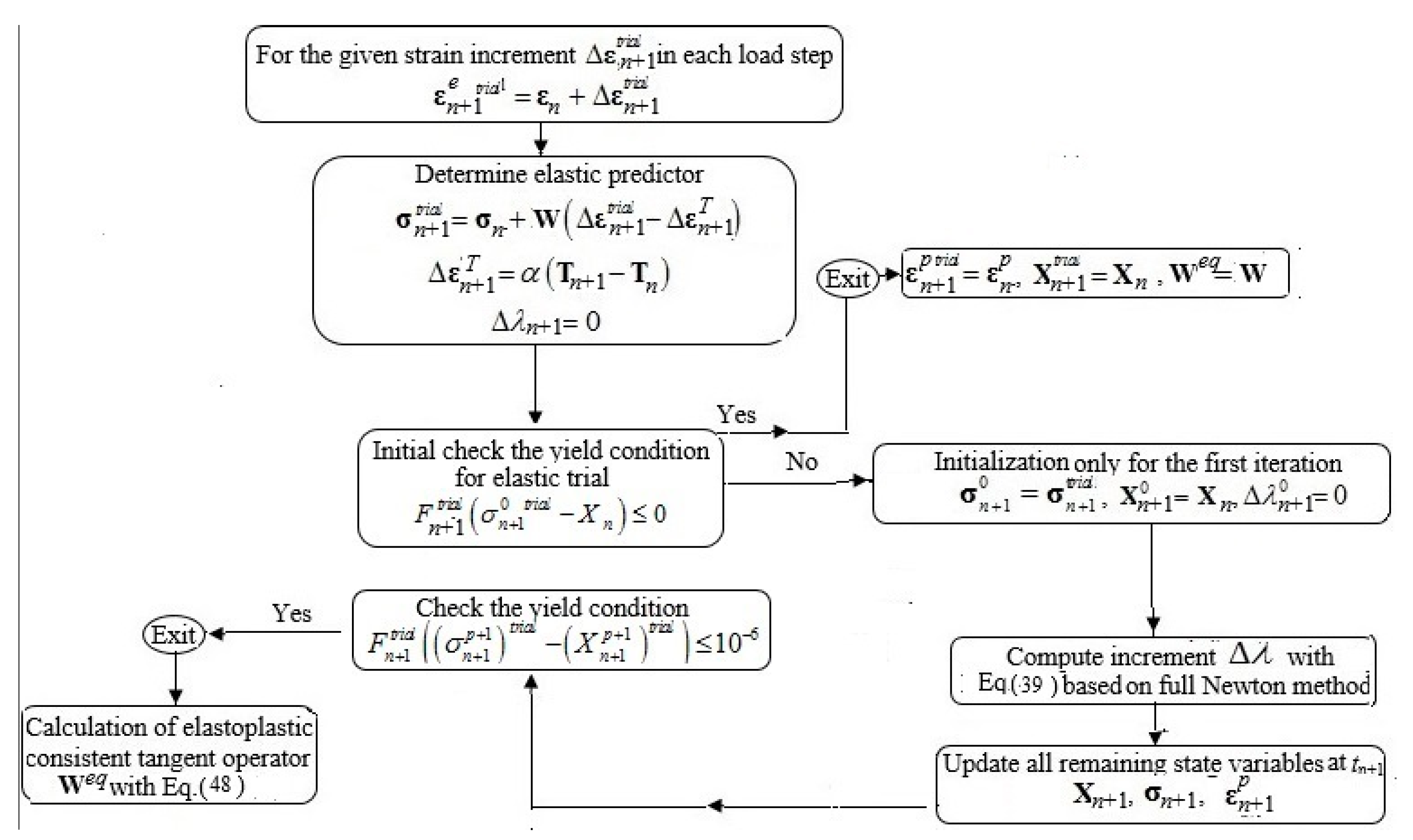
The numerical simulation of cyclic elastoplastic problems requires the constitutive equations in the rate form to be integrated so as to reproduce the effective material response. In this research, the well-known return mapping algorithm (RMA), originally proposed by Simo and Hughes [31], is implemented to provide an efficient numerical solution of the cyclic elasto-plastic constitutive model. In such a problem, the variables expressed in the rate form are required to be integrated within the time interval [tn, tn+1], where n and n+1 subscripts are the previous and current load steps, respectively. Using the implicit backward Euler method, the set of constitutive equations are discretized and all the rate quantities are replaced with corresponding incremental unknowns. Assuming that the loading histories illustrated in Figure 1b and Figure 2b are prescribed in the total time interval length [0, t t ] that, in turn, is partitioned into N sub-intervals by a sequence of discrete time steps t0 < t1 < t2 <… < t N with tn+1 = tn + Δt. It is possible to implement the methodology of the RMA for updating the state variables in each sample point. The trial elastic strain is obtained by a given prescribed incremental strain Δ ε :
ε n + 1 e t r i a l = ε n + Δ ε
Elastic behavior is initially supposed within the time interval [tn, tn+1] (Δλ = 0). For the given strain increment, the trial elastic state takes the following forms:
Δ σ n + 1 t r i a l = W ( Δ ε n + 1 e t r i a l ε n + 1 T ) ε n + 1 T = α ( T n + 1 T n ) ε n + 1 p t r i a l = ε n p X n + 1 t r i a l = X n
In addition, the computed trial stress and strain tensors are divided into deviatoric σ n + 1 t r i a l and ( ε d e ) n + 1 t r i a l , and also hydrostatic ( σ H ) n + 1 t r i a l and ( ε v e ) n + 1 t r i a l , parts as follows:
σ n + 1 t r i a l = σ n + 1 t r i a l + ( σ H ) n + 1 t r i a l I ( ε n + 1 e ) t r i a l = ( ε d e ) n + 1 t r i a l + ( ε v e ) n + 1 t r i a l I
where
( σ H ) n + 1 t r i a l = ( 1 / 3 ) t r ( σ n + 1 t r i a l ) = ( E / 3 ( 1 2 υ ) ) ( ( ε v e ) n + 1 t r i a l 3 Δ ε n + 1 T ) = K ( ( ε v e ) n + 1 t r i a l ε n + 1 T ) I I
σ n + 1 t r i a l = 2 G ( ε d e ) n + 1 t r i a l I d
Here, I d denotes the deviatoric part of unit matrix I , K bulk modulus. Based on the obtained values of trial stress components σ n + 1 t r i a l , the trial value of yield function is evaluated:
F n + 1 t r i a l = 3 / 2 σ n + 1 t r i a l X n + 1 t r i a l σ y
If it falls within or on the yield surface F n + 1 t r i a l 0 , it is accepted as the solution to a problem. Otherwise, the results of the step are not plastically admissible and need to be corrected in the following procedure. The plastic corrector characterizes the solution as the closest-point-projection of the trial state onto the yield surface. In order to reduce the solution of the return mapping algorithm for the von Mises model to a scalar nonlinear equation having unknown Δ λ n + 1 , the following computational procedure must be implemented. The increment of elastic strain utilizing plastic strain increment of Equation (5) can be expressed as:
ε n + 1 e = ε n + 1 e t r i a l ε n + 1 T Δ ε n + 1 p = ε n + 1 e t r i a l ε n + 1 T Δ λ n + 1 3 / 2 ( ( σ n + 1 X n + 1 ) / σ n + 1 X n + 1 ) = ε n + 1 e t r i a l ε n + 1 T Δ λ n + 1 3 / 2 ( β n + 1 / β n + 1 ) = ε n + 1 e t r i a l ε n + 1 T Δ λ n + 1 3 / 2 Ν ¯
where
N ¯ n + 1 = β n + 1 / β n + 1
Since the volumetric part of stress tensor does not affect plasticity computations, it can be evaluated without application of the return mapping algorithm, i.e., ( σ H ) n + 1 = ( σ H ) n + 1 t r i a l . Equivalently, through multiplying Equation (31) by 2G, it takes the following form:
σ n + 1 = σ n + 1 t r i a l 2 3 / 2 ( Δ λ n + 1 ) G N ¯ n + 1
With a little algebra and rearranging the terms in the Chaboche nonlinear kinematic hardening model of Equations (7-8), the following expression is yielded:
X n + 1 = ( X n / ( 1 + n = 1 3 γ n Δ λ n + 1 ) ) + ( ( 2 3 n = 1 3 C n Δ λ n + 1 ) / ( 1 + Δ λ n + 1 n = 1 3 γ n ) ) ( β n + 1 / β n + 1 )
Subtracting Equation (33) from Equation (34), gives:
σ n + 1 X n + 1 = ( σ n + 1 t r i a l X n / ( 1 + Δ λ n + 1 n = 1 3 γ n ) ) Δ λ n + 1 3 / 2 ( β n + 1 / β n + 1 ) ( 2 G + ( ( 2 3 n = 1 3 C n ) / ( 1 + Δ λ n + 1 n = 1 3 γ n ) ) )
It is evident from Equation (35) that the following identity is established:
σ n + 1 X n + 1 σ n + 1 X n + 1 = j n + 1 t r i a l j n + 1 t r i a l
where
j n + 1 t r i a l = 3 / 2 σ n + 1 t r i a l X n / ( 1 + Δ λ n + 1 n = 1 3 γ n )
Using the relation of Equation (36), the following expression for Equation (35) is obtained:
σ n + 1 X n + 1 = ( σ n + 1 t r i a l X n / ( 1 + n = 1 3 γ n Δ λ n + 1 ) ) ( 1 Δ λ n + 1 3 / 2 ( 2 G + ( 2 3 n = 1 3 C n / 1 + n = 1 3 γ n Δ λ n + 1 ) ) / σ n + 1 t r i a l X n / ( 1 + Δ λ n + 1 n = 1 3 γ n ) ) )
Finally, using Equation (38), the yield criterion, i.e., F n + 1 = 0, is written as:
F n + 1 = 3 / 2 σ n + 1 t r i a l X n / ( 1 + n = 1 3 γ n Δ λ n + 1 ) Δ λ n + 1 ( 3 G + ( n = 1 3 C n / 1 + n = 1 3 γ n Δ λ n + 1 ) ) σ y = 0
Equation (39) is effectively solved by the iterative method of Newton-Raphson procedure with pth iterations and designated tolerance (tol = 10−6) [25] to obtain the incremental plastic multiplier Δ λ n + 1 . After finding Δ λ n + 1 , the remaining variables at time tn+1 including ε p n + 1 , σ n + 1 and X n + 1 are updated. Finally, the consistent elastoplastic tangent operator ( W e p ) is established to preserve the asymptotic quadratic rate of convergence of the Newton-Raphson method. Using Equations (28), (33), (34) and (35), the total stress at time tn+1 takes the following expression:
σ n + 1 = σ n + 1 + ( σ H ) n + 1 t r i a l I
σ n + 1 = [ W e 6 G 2 Δ λ n + 1 I d / ( j n + 1 t r i a l ) ] ( ( ε e ) n + 1 t r i a l ε n + 1 T ) + 3 G Δ λ n + 1 i = 1 3 X i / j n + 1 t r i a l ( 1 + Δ λ n + 1 n = 1 3 γ n )
The consistent elastoplastic tangent operator is defined through differentiation of total stress with respect to ( ( ε e ) n + 1 t r i a l ε n + 1 T ) in Equation (41) as:
W e p = σ n + 1 ( ε n + 1 e t r i a l ε n + 1 T ) = W e 6 G 2 Δ λ n + 1 I d / j n + 1 t r i a l [ 6 G 2 ( ε n + 1 e t r i a l ε n + 1 T ) I d / ( j n + 1 t r i a l ) 3 G i = 1 3 X i / ( 1 + Δ λ n + 1 n = 1 3 γ n ) 2 j n + 1 t r i a l ] Δ λ n + 1 ( ε n + 1 e t r i a l ε n + 1 T ) + [ 6 G 2 Δ λ n + 1 ( ε n + 1 e t r i a l ε n + 1 T ) I d / ( j n + 1 t r i a l ) 2 3 G Δ λ n + 1 i = 1 3 X i / ( 1 + Δ λ n + 1 n = 1 3 γ n ) ( j n + 1 t r i a l ) 2 ] j n + 1 t r i a l ( ε n + 1 e t r i a l ε n + 1 T )
Applying Equation (33) leads to:
W e p = W 6 G 2 Δ λ n + 1 I d / j n + 1 t r i a l 3 G j n + 1 t r i a l [ σ n + 1 t r i a l n = 1 3 X n / ( 1 + Δ λ n + 1 n = 1 3 γ n ) 2 ] Δ λ n + 1 ( ε n + 1 e t r i a l ε n + 1 T ) + 3 G ( j n + 1 t r i a l ) 2 [ σ n + 1 t r i a l n = 1 3 X n / ( 1 + Δ λ n + 1 n = 1 3 γ n ) ] j n + 1 t r i a l ( ε n + 1 e t r i a l ε n + 1 T )
The relationship between j n + 1 t r i a l / ( ε n + 1 e t r i a l ε n + 1 T ) and Δ λ n + 1 / ( ε n + 1 e t r i a l ε n + 1 T ) is derived through differentiation of Equation (39) with respect to ( ε n + 1 e t r i a l ε n + 1 T ) as follows:
( ε n + 1 e t r i a l ε n + 1 T ) ( j n + 1 t r i a l Δ λ n + 1 ( 3 G + ( n = 1 3 C n / 1 + Δ λ n + 1 n = 1 3 γ n ) ) σ y ) = 0
Through algebraic manipulation and rearranging the Equation (44), the following result is yielded:
j n + 1 t r i a l ( ε n + 1 e t r i a l ε n + 1 T ) = ( 3 G + n = 1 3 C n / ( 1 + n = 1 3 γ n Δ λ n + 1 ) 2 ) Δ λ n + 1 ( ε n + 1 e t r i a l ε n + 1 T )
where:
Δ λ n + 1 ( ε n + 1 e t r i a l ε n + 1 T ) = 3 / 2 N ¯ n + 1 ( 2 G ) / 3 G + n = 1 3 C n / ( 1 + n = 1 3 γ n Δ λ n + 1 ) 2 ( 3 / 2 N ¯ n + 1 n = 1 3 X n ( n = 1 3 γ n / ( 1 + Δ λ n + 1 n = 1 3 γ n ) 2 ) ) = 3 / 2 N ¯ n + 1 χ
Substituting Equation (45) into Equation (46) gives:
j n + 1 t r i a l ( ε n + 1 e t r i a l ε n + 1 T ) = 3 / 2 N ¯ n + 1 ( 2 G ) ( 3 G + n = 1 3 C n / ( 1 + n = 1 3 γ n Δ λ n + 1 ) 2 ) / 3 G + n = 1 3 C n / ( 1 + n = 1 3 γ n Δ λ n + 1 ) 2 ( 3 / 2 N ¯ n + 1 n = 1 3 X n ( n = 1 3 γ n / ( 1 + Δ λ n + 1 n = 1 3 γ n ) 2 ) ) = 2 G 3 / 2 v N ¯ n + 1
Using Equations (43), (46) and (47) with simple manipulation, the following expression for the applied constitutive model is derived as:
W e p = 2 G ( 1 3 G Δ λ n + 1 j n + 1 t r i a l ) I d + ( K ) I I ( 3 G χ ) N ¯ N ¯ + ( 6 G 2 Δ λ n + 1 j n + 1 t r i a l v ) N ¯ N ¯
where j n + 1 t r i a l , K , χ , N ¯ and v were defined in Equations (37), (28), (46), (32) and (47). The stress integration method applied for the present elastic–plastic constitutive equations through the user-defined material subroutine (UMAT) is summarized and presented in Figure 3.

5. Numerical Results

5.1. Internally Pressurized FGM Pipe under Cyclic Bending Moment

In this research, it is assumed that the FGM pipe is made up of carbon steel (CS) grade 1026 with corresponding material properties listed in Table 1. The ratio of outer to inner radii of the FGM pipe is taken to be b/a = 1.3. For the selected FGM pipe, two cases are considered. Case one, FGM properties are assumed to continuously change from those of CS 1026, located at the outer surface, to those with FGM grading indexes of m1 = 3, m2 = −1.1, m3 = 3, m4 = 2 and m5 = −1.5 at the inner surface. Case two, the inner surface of FGM pipe consists of pure CS 1026 and the properties smoothly vary along the radial direction according to Equation (12) with material in-homogeneity parameters of m1 = −3, m2 = 1.1, m3 = −3, m4 = −2 and m5 = 1.5 at the inner surface [28].
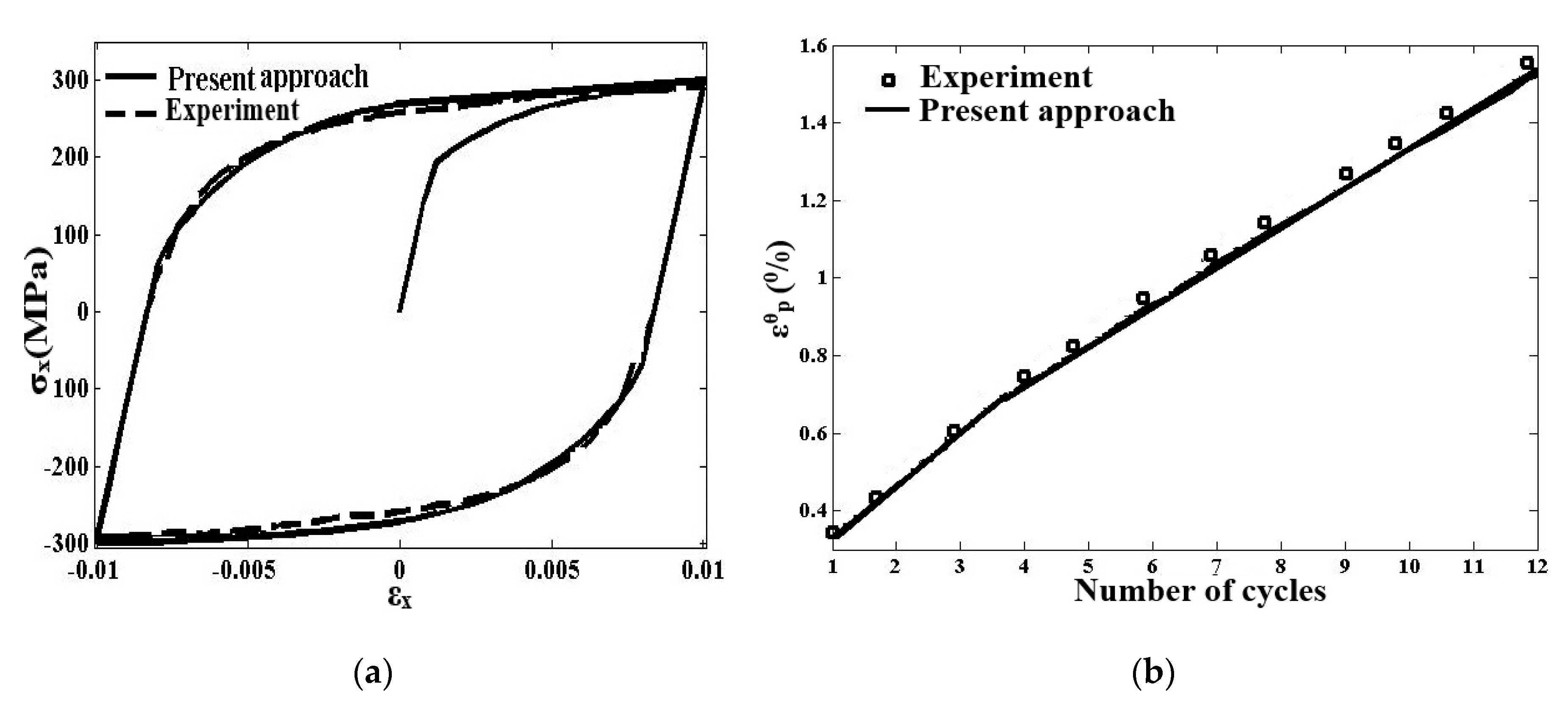
In order to validate the capabilities of the proposed numerical technique in predicting the elastic–plastic behaviors of metals under cyclic loading conditions, the comparisons were carried out with those given by experiments [32]. The experiments were conducted on a tube made from CS 1026 under loading conditions consisting of: cyclic, symmetric, axial strain-controlled loading as in Figure 4a; and axially strain symmetric cycling with an amplitude of 0.5% combined with a steady internal pressure of 46.767 MPa as in Figure 4b. It is possible to remark that the present approach gives results that are very close to the experimental results, providing validation. It is worth mentioning that the stable hysteresis loop achieved after 12 cycles was chosen and illustrated in Figure 4a. It is worthwhile to emphasize that, in order to calibrate the prediction modeling, the stable hysteresis loop experimentally achieved after 12 cycles was chosen as shown in Figure 4a.
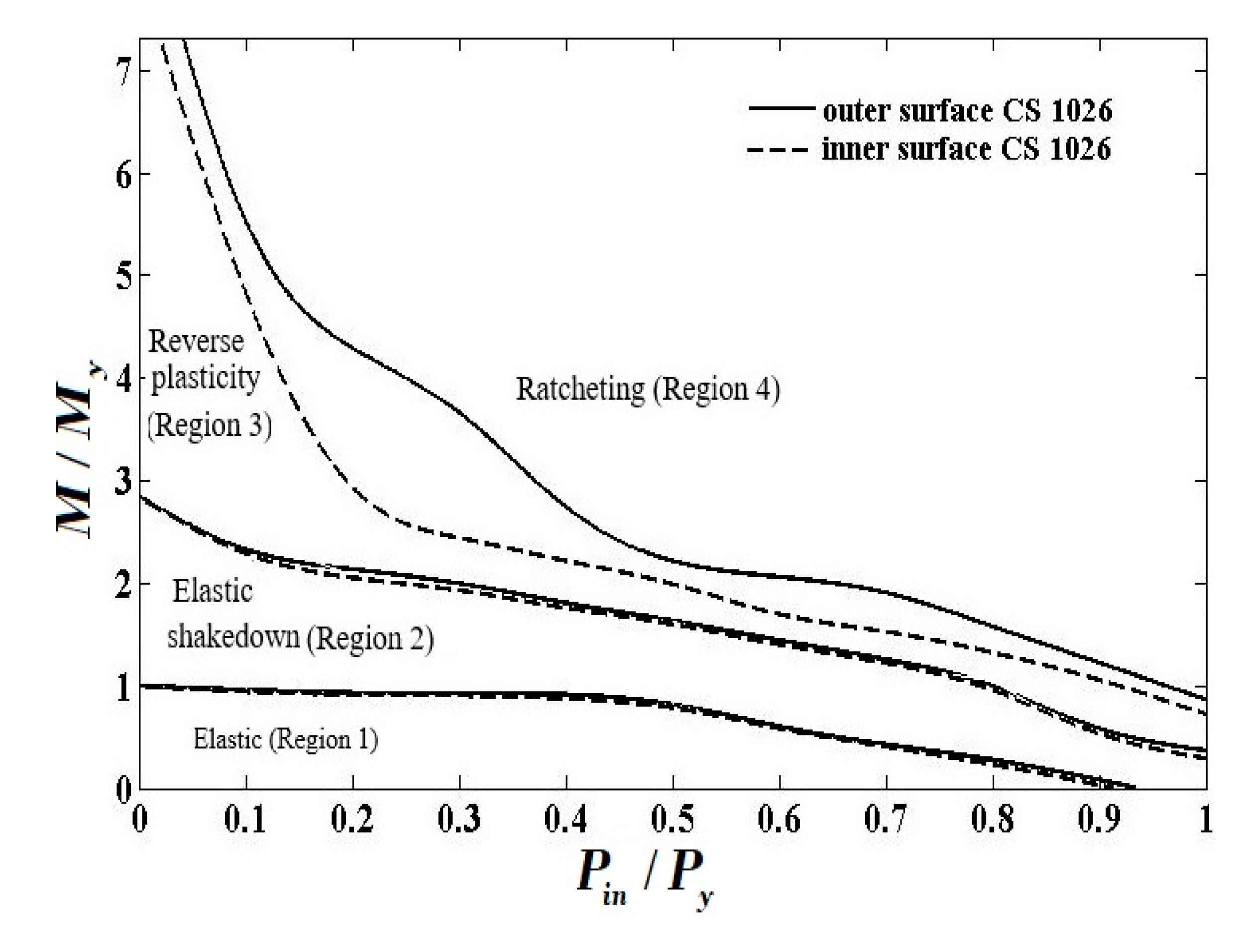
Different modes of cyclic behaviors—namely, completely elastic state, elastic shakedown, reverse plasticity (plastic shakedown and ratcheting in the structures)—become evident under various load combinations. In order to analyze the cyclic behaviors of the FGM pipe with the inner and outer surfaces in steel under two types of prescribed loading conditions, the interaction diagrams known as Bree’s diagrams are presented in this section. Bree’s diagrams have abscissas and ordinates that denote the levels of constant and cyclic loading levels, respectively. These diagrams help illustrate a variety of cyclic responses of structures under different loading conditions. It should be noted that although the analysis can be extremely tedious and lengthy, the results can be plotted in a simple graphical form. Bree diagrams identifying cyclic stress regime limits have been extensively utilized in different engineering sections. It should also be mentioned that the corresponding results in Figure 5, Figure 6, Figure 7, Figure 8, Figure 9, Figure 10, Figure 11, Figure 12 and Figure 13, are based upon the responses of the inner surface of the FGM pipe for both designated designs.
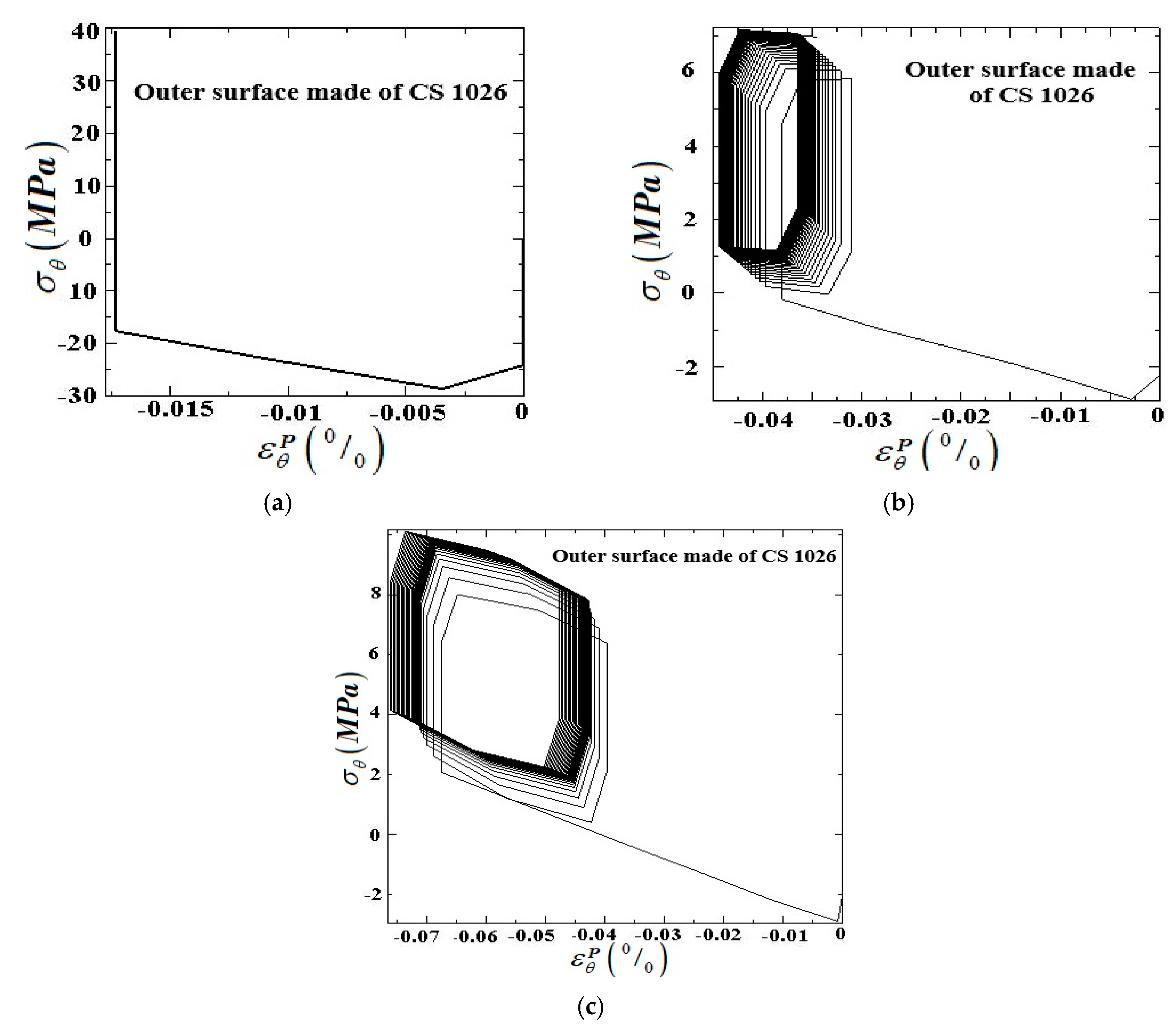
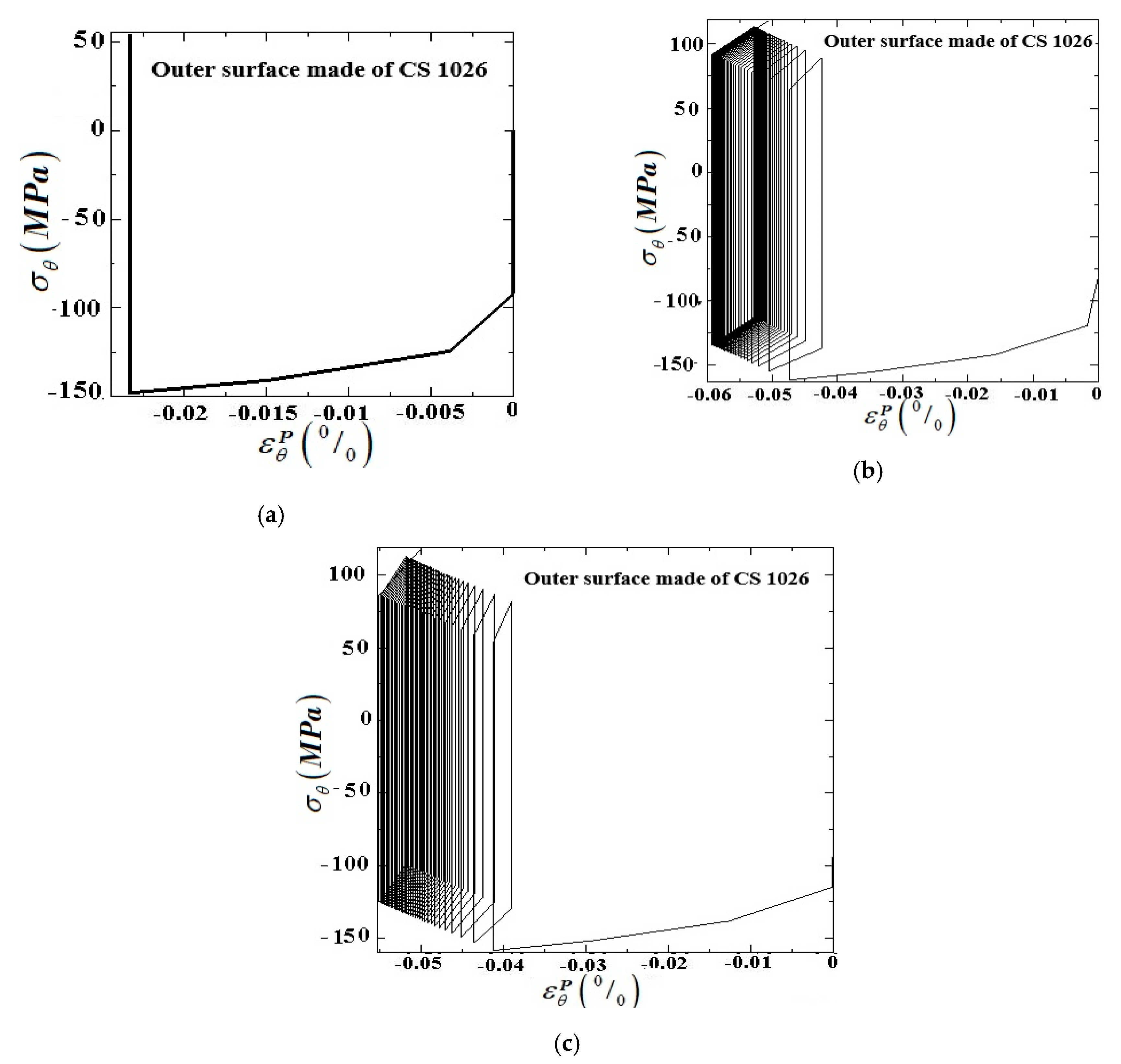
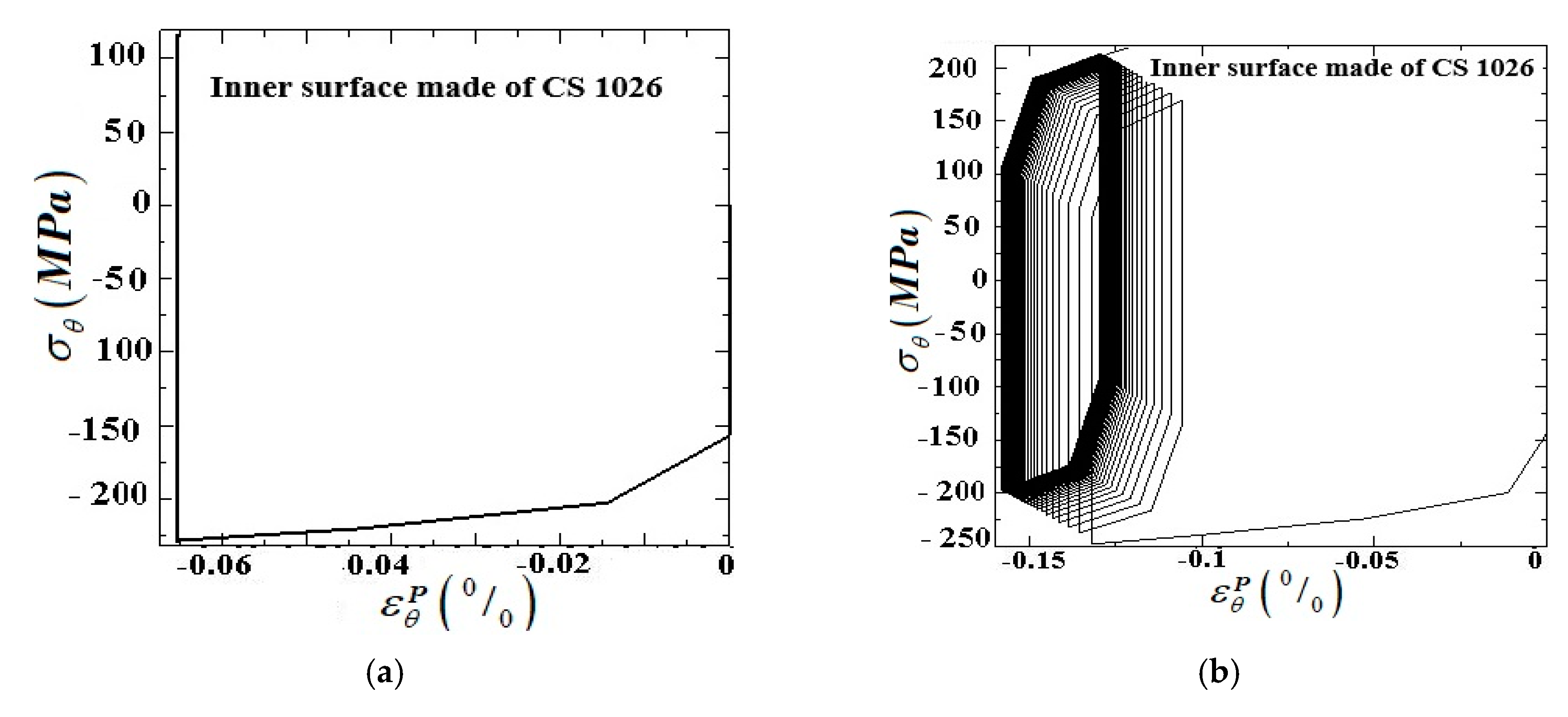
It is of interest to interpret the different cyclic plasticity regimes and illustrate their representative hysteresis loops. The first possibility is to have a pure elastic stress state, with no plastic deformation. The second possibility is to allow for the elastic shakedown involving the plastic zone during the first load cycles, but ultimately shakedown to state with purely elastic behavior with an elastic response to further cycling. The third possibility is that the FGM pipe may incur reversed plasticity; in this case, the stress and strain will cycle along a closed loop with a vanishing total plastic strain per cycle. The last cyclic characteristic response of the structure is based on the allowance for ratcheting, with plastic strain rate not only changing the sign but also with the accumulation of plastic strain in each cycle. Figure 5a–c shows the typical stress–plastic strain hysteresis curve in the hoop direction for three kinds of cyclic responses of the FGM pipe with the outer surface made of CS 1026. In addition, the typical hysteresis loops of stress–plastic strain in the hoop direction of FGM pipe with the inner surface made of CS 1026 for three cyclic elastic–plastic responses, as discussed earlier, are depicted in Figure 6a–c Based on four different possible cyclic responses exhibited by the internally pressurized FGM pipe under cyclic bending, the interaction diagram can bring them together in one diagram, such as that shown in Figure 7. It should be noted that for both types of FGM pipe, the internal pressure and cyclic bending moment are normalized with respect to their own yield pressure (py) and yield bending moment (My), respectively. Note that the dashed and solid lines that determine the boundaries between cyclic stress regimes are representatives’ lines of FGM pipe with the inner/outer surfaces made up of CS 1026, respectively.
From Figure 7 it is possible to note that for the FGM pipe with its outer surface made up of CS 1026, the reverse plasticity domain is significantly larger than in the case of the FGM pipe with the inner surface made up of CS 1026. This means that changing the FGM properties through the thickness has a significant influence on the size of the ratcheting domain. The deviation between the curves which specify the boundary between the ratcheting and plastic shakedown domains is much more noticeable between 0.2 and 0.4 normalized steady internal pressure. It is also noticed that the curves specifying the elastic and elastic shakedown ranges are almost overlapping in both designs of FGM pipe. From this output, it can be inferred that the variations of material properties are the most critical points within the FGM pipe since they control the ratcheting responses as the root cause of failure.
Hence, the processing parameters, used in the manufacturing of FGM composite materials, can be modified to drive the variations of microstructures and subsequently the performances of the material in relation to the given application. This characteristic distinguishes FGM composite materials from monolithic and homogeneous composite materials.

5.2. The Numerical Results of Internally Pressurized FG Pipe under Cyclic through the Thickness Temperature Gradient

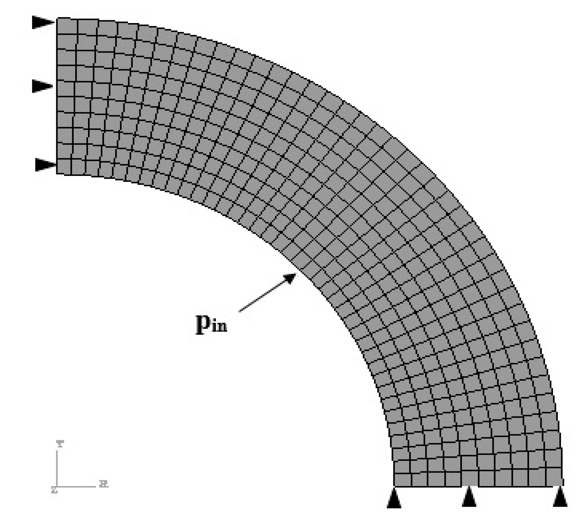
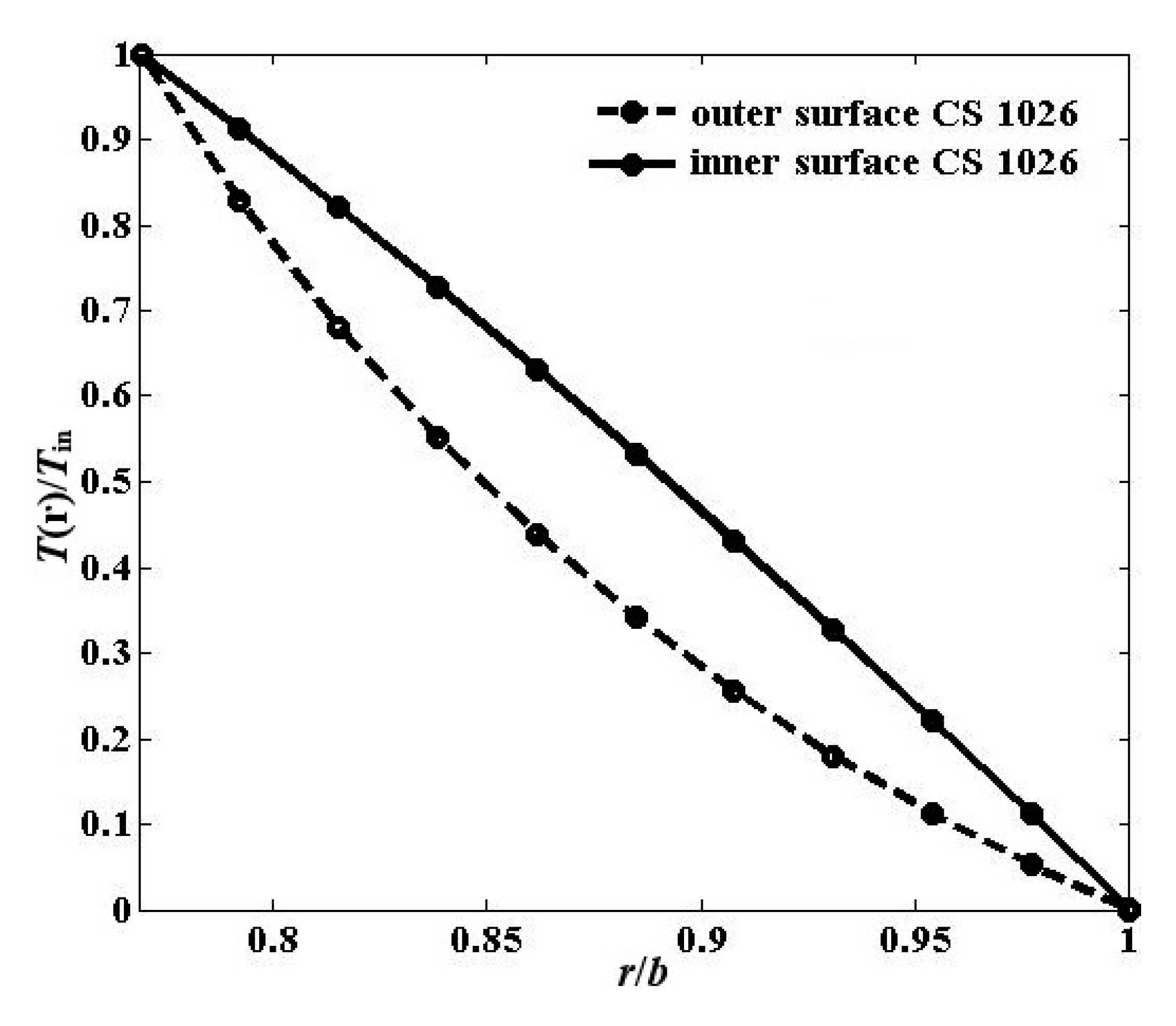
The 2D case of an infinite pipe with 390 quadratic quadrilateral elements of type CPE8R, as shown in Figure 8, was employed to simulate in ABAQUS finite element code. Moreover, in order to show the through-thickness temperature profiles of the two adopted FG pipes, based on Equations (20) and (21), the variations of dimensionless temperature defined as T(r)/Tin versus dimensionless radial direction r/b is presented in Figure 9.
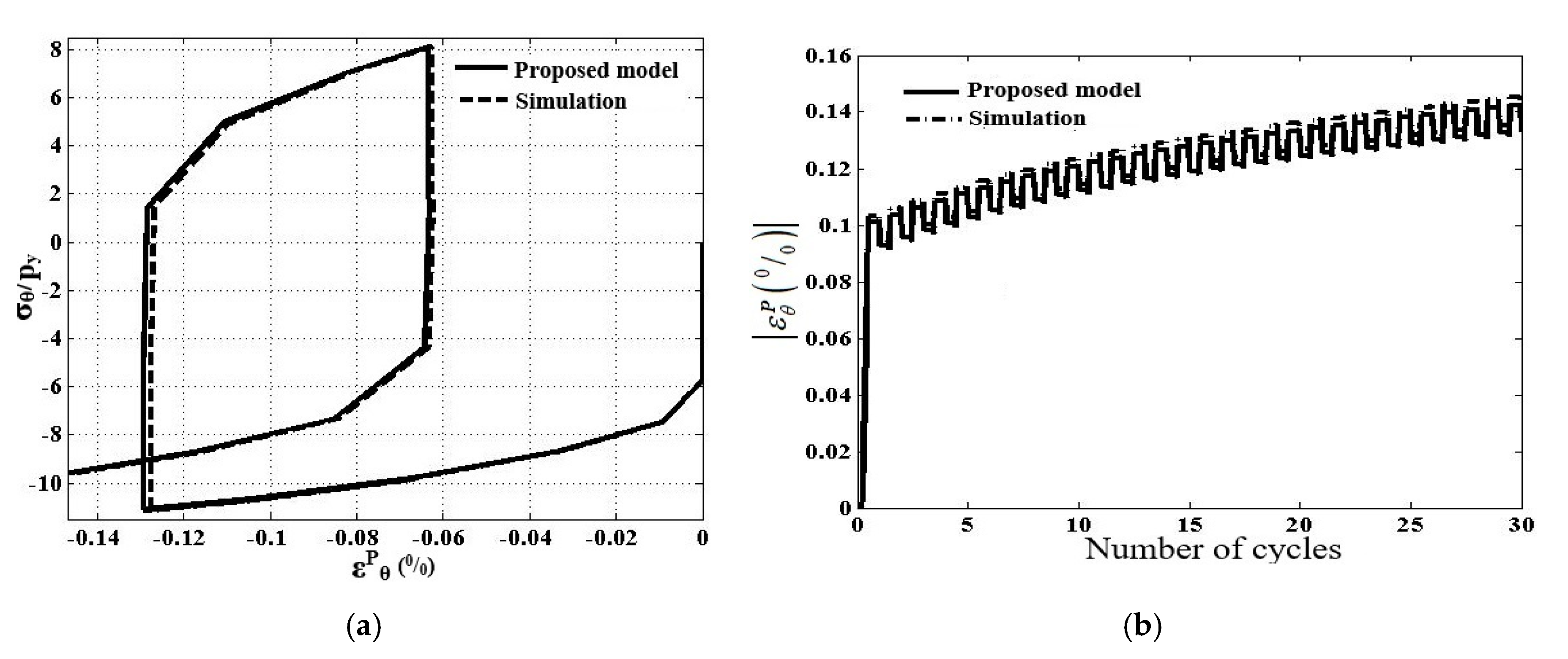
In order to confirm the performances of the proposed computational algorithm under thermal effects, the comparisons against the simulation obtained by ABAQUS/standard are carried out and shown in Figure 10a,b. It should be noted, Figure 10a,b, that for an FGM pipe made with an outer surface containing pure CS 1026, Ty and py represent the temperature and pressure causing initial yielding, respectively, equals to 84 °C and 20.5 MPa. The hysteresis curve of non-dimensional circumferential stress ( σ θ / p y ) versus ε p θ and also the variations of absolute values of ε p θ as a function of the number of cycles for the homogeneous pipe with a geometric parameter of b/a = 1.3 and the material properties listed in Table 1 are plotted in Figure 10a,b, respectively.
According to Figure 10a,b, it is easily realized that the predicted dimensionless circumferential stress–plastic strain curve by the present approach agrees well with those obtained by ABAQUS simulation. Figure 11, Figure 12 and Figure 13 show the cyclic elastoplastic behavior of the FGM pipe subjected to steady internal pressure and a cyclic through-thickness temperature gradient, as illustrated in Figure 2b, using the corresponding material given in Table 1 and the ratio of outer to inner radii of 1.3.
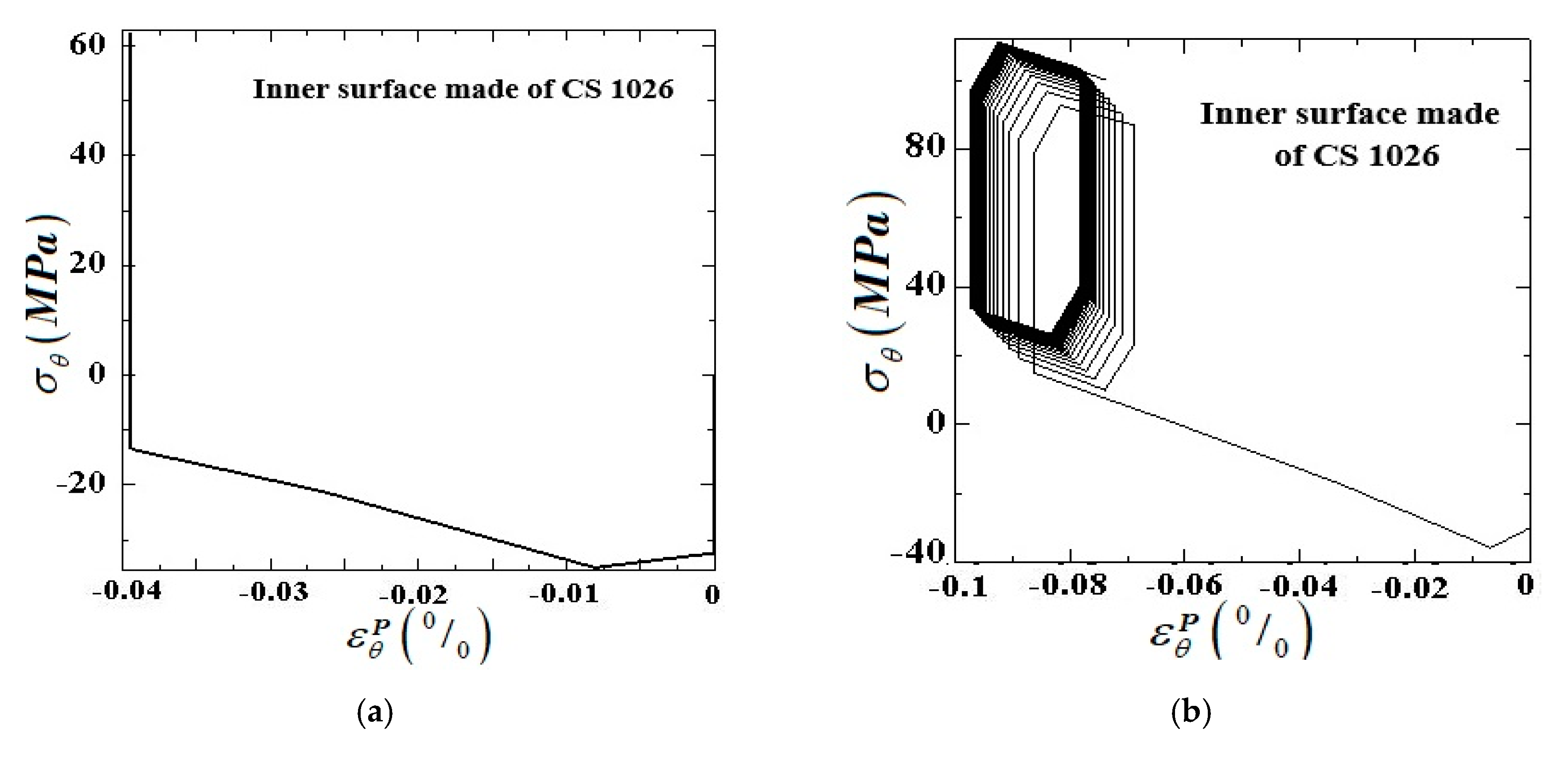
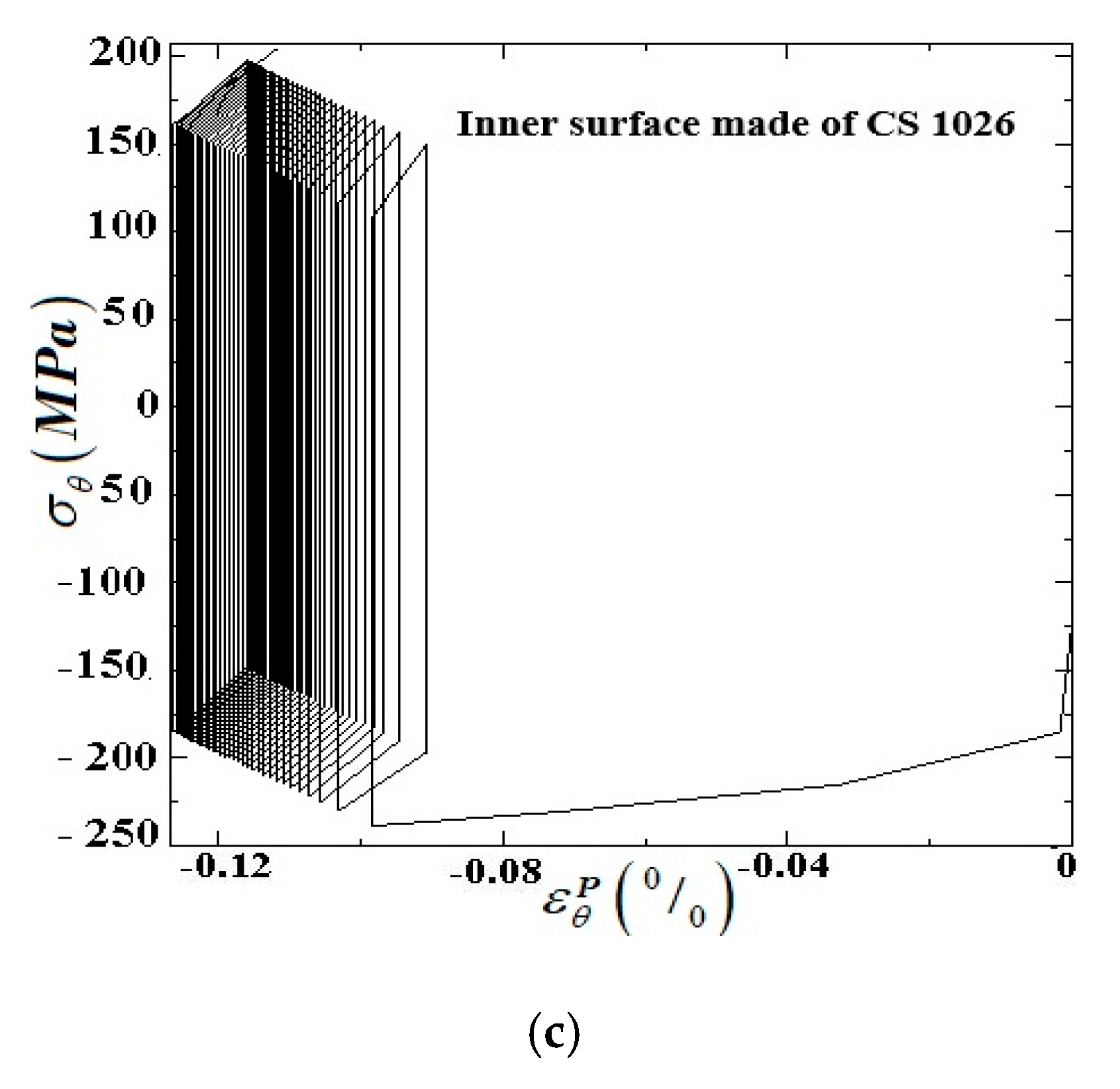
The behaviors of the two different designs of FGM pipes under arbitrary loading conditions, with the pure CS 1026 on the inner and outer surfaces, are well exemplified by their representative hysteresis stress–plastic strain loops in the circumferential direction under the specified loading conditions, as illustrated in Figure 11 and Figure 12. Based on these findings, the extensions of stress regime zones occurring at the inner wall of the FGM pipe are identified and brought together in the interaction diagram in Figure 13. The dashed and solid lines in Figure 13 identify the extensions of cyclic plasticity regimes for FGM pipes with the inner and outer surfaces made up of CS 1026, respectively. Note that like the prior Bree’s diagram presented in Figure 7, internal pressure and thermal loading are given in percentages of yield pressure py and yield thermal loadings Ty of the FGM pipes with outer surface in CS 1026, respectively.
The interaction diagram in Figure 13 indicates that using an FGM pipe with the inner surface made up of CS 1026 causes a shift of the curves determining the boundaries between the cyclic plasticity regimes to the lower thermal loading levels. However, the curve that determines the boundary between reversed plasticity and ratcheting domains, is at a higher or lower thermal loading level for the considered pressure range depending on the FGM pipe having the outer rather than the inner surface made up of CS 1026.
Moreover, as can be seen from Figure 13, the FGM pipe with the inner surface made from CS 1026 reaches a plastic shakedown condition in correspondence of lower levels of thermal loading, over the whole region 0 < Pin/Py < 1, than the FGM pipe made with the outer surface in pure CS1026. This means that the largest plastic shakedown limit is achieved for FGM pipe with the inner surface made from CS 1026. It is also found that, for FGM pipe with the inner surface made from CS 1026, the curve specifying the boundary between elastic and elastic shakedown, for a normalized internal pressure in the range 0: ≈ 0.7 shows lower thermal loading compared to FGM with outer surface CS 1026, whereas the reverse happens for a normalized internal pressure between 0.7 and 1.
It is important to point out that the above results regarding Figure 7 and Figure 13 entail a future need to carry out a parametric study to investigate the effects of the compositional variations between constituent phases on cyclic responses of FGM pipes in order to achieve an optimum design.

6. Conclusions

This paper investigated the various responses of two different designs of FGM pipes that undergo two different load cases involving (1) cyclic bending moment and steady internal pressure (2) cyclic thermal loading associated with through-thickness temperature gradients and steady internal pressure. The material properties of the FGM, except Poisson’s ratio, were assumed to obey a power-law function along the radial direction. The Chaboche nonlinear kinematic hardening model was set to simulate the hardening behavior of the FGM pipe with variable parameters changing according to power-law distribution across the thickness direction. The return mapping algorithm using an elastic predictor and plastic corrector phases was proposed to carry out the numerical simulation. The performances of the applied numerical procedure performed within a UMAT user subroutine were verified by cross-checking numerical results against experimental results and FE simulations: good agreements were obtained for all. To study the cyclic elastoplastic responses of the FGM pipes under two types of loading conditions, the interaction diagrams for the two FGM profiles—one with the inner surface and one with the outer surface made up of CS 1026—were presented. The results for the cyclic bending and steady internal pressure showed that the FGM pipe with its outer surface made up of CS 1026 exhibited higher resistance to bending (with the same internal pressure) before reaching cyclic plasticity regimes and also avoided premature failure caused by ratcheting. In addition, the significant influences of radially varying material distributions of FGM pipes under thermomechanical loadings on Bree’s diagram were observed. To sum up the results of Bree’s diagrams, it was concluded that different designs of FGM pipes showed different cyclic behaviors. Therefore, the material properties gradient of FGM piping systems should be tailored to the specific function and application, particularly for shrinking the ratcheting domain as a potential mechanism for mitigating failure.

Author Contributions

Writing–Original Draft Preparation, A.M.; Writing–Review & Editing, R.S. and E.A. and J.W.; Supervision, S.A.S. and R.C. All authors have read and agreed to the published version of the manuscript.

Funding

This research received no external funding.

Conflicts of Interest

The authors declare no conflict of interest.

Nomenclature

Back stress rate X ˙ Poisson’s ratioν
Bending momentMPlastic multiplier rate λ ˙
Chaboche material parameters C 0 l and γ 0 l Rates of stress σ ˙ i j
Coefficient of thermal expansion α 0 Thermal conductivity k
Deviatoric back stress increment X Thermal strain rate ε ˙ T
Deviatoric stress σ Total rates of strain, elastic, thermal and plastic strains ε ˙ , ε ˙ p , ε ˙ e , ε ˙ T
Equivalent plastic strain rate ε ˙ e p Trial variables σ t r i a l , ε t r i a l , X t r i a l
Internal pressure PinYield stress σ y 0
FGM grading indexes miYield bending moment M y
Fourth-order stiffness tensor W Yield pressure, temperaturepy, Ty
Outer and inner surfaces temperature Tout, TinYoung’s modulusE0
Inertia moment I r Inner and outer radii of FGM pipea, b

References

  1. Armstrong, P.J.; Frederick, C.O. A Mathematical Representation of the Multiaxial Bauschinger Effect; Central Electricity Generating Board and Berkeley: London, UK, 1966. [Google Scholar]
  2. Chaboche, J. On some modifications of kinematic hardening to improve the description of ratchetting effects. Int. J. Plast. 1991, 7, 661–678. [Google Scholar] [CrossRef]
  3. Ohno, N.; Wang, J.-D. Kinematic hardening rules with critical state of dynamic recovery, part I: Formulation and basic features for ratchetting behavior. Int. J. Plast. 1993, 9, 375–390. [Google Scholar] [CrossRef]
  4. McDowell, D. Stress state dependence of cyclic ratchetting behavior of two rail steels. Int. J. Plast. 1995, 11, 397–421. [Google Scholar] [CrossRef]
  5. Jiang, Y.; Sehitoglu, H. Modeling of Cyclic Ratchetting Plasticity, Part I: Development of Constitutive Relations. J. Appl. Mech. 1996, 63, 720–725. [Google Scholar] [CrossRef]
  6. Abdel-Karim, M.; Ohno, N. Kinematic hardening model suitable for ratchetting with steady-state. Int. J. Plast. 2000, 16, 225–240. [Google Scholar] [CrossRef]
  7. Chen, X.; Jiao, R.; Kim, K.S. On the Ohno—Wang kinematic hardening rules for multiaxial ratcheting modeling of medium carbon steel. Int. J. Plast. 2005, 21, 161–184. [Google Scholar] [CrossRef]
  8. Rahman, S.M.; Hassan, T.; Corona, E. Evaluation of cyclic plasticity models in ratcheting simulation of straight pipes under cyclic bending and steady internal pressure. Int. J. Plast. 2008, 24, 1756–1791. [Google Scholar] [CrossRef]
  9. Wang, L.; Chen, G.; Zhu, J.; Sun, X.; Mei, Y.; Ling, X.; Chen, X. Bending ratcheting behavior of pressurized straight Z2CND18.12N stainless steel pipe. Struct. Eng. Mech. 2014, 52, 1135–1156. [Google Scholar] [CrossRef]
  10. Rokhgireh, H.; Nayebi, A. Cyclic uniaxial and multiaxial loading with yield surface distortion consideration on prediction of ratcheting. Mech. Mater. 2012, 47, 61–74. [Google Scholar] [CrossRef]
  11. Duarte, A.P.C.; Silva, B.A.P.; Silvestre, N.; De Brito, J.; Julio, E.; Castro, J. Experimental study on short rubberized concrete-filled steel tubes under cyclic loading. Compos. Struct. 2016, 136, 394–404. [Google Scholar] [CrossRef]
  12. Ahmadzadeh, G.; Varvani-Farahani, A.; Varvani-Farahani, A. A kinematic hardening rule to investigate the impact of loading path and direction on ratcheting response of steel alloys. Mech. Mater. 2016, 101, 40–49. [Google Scholar] [CrossRef]
  13. Chen, H.; Ure, J.; Li, T.; Chen, W.; MacKenzie, N. Shakedown and limit analysis of 90° pipe bends under internal pressure, cyclic in-plane bending and cyclic thermal loading. Int. J. Press. Vessel. Pip. 2011, 88, 213–222. [Google Scholar] [CrossRef] [Green Version]
  14. Mattos, H.D.C.; Peres, J.M.; Melo, M.A.C. Ratcheting behaviour of elasto-plastic thin-walled pipes under internal pressure and subjected to cyclic axial loading. Thin Walled Struct. 2015, 93, 102–111. [Google Scholar] [CrossRef]
  15. Amirpour, M.; Das, R.; Bickerton, S. An elasto-plastic damage model for functionally graded plates with in-plane material properties variation: Material model and numerical implementation. Compos. Struct. 2017, 163, 331–341. [Google Scholar] [CrossRef]
  16. Eraslan, A.N.; Akış, T. Plane strain analytical solutions for a functionally graded elastic–plastic pressurized tube. Int. J. Press. Vessel. Pip. 2006, 83, 635–644. [Google Scholar] [CrossRef]
  17. Mukhtar, F.M.; Al-Gadhib, A.H. Collocation Method for Elastoplastic Analysis of a Pressurized Functionally Graded Tube. Arab. J. Sci. Eng. 2014, 39, 7701–7716. [Google Scholar] [CrossRef]
  18. Peng, X.; Zheng, H.; Hu, N.; Fang, C. Static and kinematic shakedown analysis of FG plate subjected to constant mechanical load and cyclically varying temperature change. Compos. Struct. 2009, 91, 212–221. [Google Scholar] [CrossRef]
  19. Farhatnia, F.; Babaei, J.; Foroudastan, R. Thermo-Mechanical Nonlinear Bending Analysis of Functionally Graded Thick Circular Plates Resting on Winkler Foundation Based on Sinusoidal Shear Deformation Theory. Arab. J. Sci. Eng. 2017, 43, 1137–1151. [Google Scholar] [CrossRef]
  20. Zhang, L.; Xuewu, L. Buckling and vibration analysis of functionally graded magneto-electro-thermo-elastic circular cylindrical shells. Appl. Math. Model. 2013, 37, 2279–2292. [Google Scholar] [CrossRef]
  21. Loghman, A.; Arani, A.G.; Amir, S.; Vajedi, A. Magnetothermoelastic creep analysis of functionally graded cylinders. Int. J. Press. Vessel. Pip. 2010, 87, 389–395. [Google Scholar] [CrossRef]
  22. Behravan-Rad, A. Thermo-elastic analysis of functionally graded circular plates resting on a gradient hybrid foundation. Appl. Math. Comput. 2015, 256, 276–298. [Google Scholar] [CrossRef]
  23. Wang, Y.; Liu, D.; Wang, Q.; Zhou, J. Asymptotic analysis of thermoelastic response in functionally graded thin plate subjected to a transient thermal shock. Compos. Struct. 2016, 139, 233–242. [Google Scholar] [CrossRef] [Green Version]
  24. Sadrabadi, S.A.; Rahimi, G.; Citarella, R.; Karami, J.S.; Sepe, R.; Esposito, R. Analytical solutions for yield onset achievement in FGM thick walled cylindrical tubes undergoing thermomechanical loads. Compos. Part B Eng. 2017, 116, 211–223. [Google Scholar] [CrossRef]
  25. De Souza Neto, E.A.; Peric, D.; Owen, D.R. Computational Methods for Plasticity: Theory and Applications; John Wiley & Sons: Hoboken, NJ, USA, 2011. [Google Scholar]
  26. Chaboche, J. Time-independent constitutive theories for cyclic plasticity. Int. J. Plast. 1986, 2, 149–188. [Google Scholar] [CrossRef]
  27. Chaboche, J. Constitutive equations for cyclic plasticity and cyclic viscoplasticity. Int. J. Plast. 1989, 5, 247–302. [Google Scholar] [CrossRef]
  28. Nayebi, A.; Sadrabadi, S.A. FGM elastoplastic analysis under thermomechanical loading. Int. J. Press. Vessel. Pip. 2013, 111, 12–20. [Google Scholar] [CrossRef]
  29. Mahbadi, H.; Eslami, M. Cyclic loading of thick vessels based on the Prager and Armstrong–Frederick kinematic hardening models. Int. J. Press. Vessel. Pip. 2006, 83, 409–419. [Google Scholar] [CrossRef]
  30. Peng, X.; Li, X.-F. Thermoelastic analysis of a cylindrical vessel of functionally graded materials. Int. J. Press. Vessel. Pip. 2010, 87, 203–210. [Google Scholar] [CrossRef]
  31. Simo, J.C.; Hughes, T.J.R. Computational Inelasticity; Springer: Berlin/Heidelberg, Germany, 2006. [Google Scholar]
  32. Hassan, T.; Kyriakides, S. Ratcheting in cyclic plasticity, part I: Uniaxial behavior. Int. J. Plast. 1992, 8, 91–116. [Google Scholar] [CrossRef]
  33. Mahmoudi, A.-H.; Pezeshki-Najafabadi, S.; Badnava, H. Parameter determination of Chaboche kinematic hardening model using a multi objective Genetic Algorithm. Comput. Mater. Sci. 2011, 50, 1114–1122. [Google Scholar] [CrossRef]
Figure 1. (a) Geometrical model of functionally graded material (FGM) cylindrical shell under constant internal pressure and cyclic bending moment. (b) Cyclic bending moment applied to the FGM cylindrical shell.
Applsci 10 02936 g001
Figure 2. (a) Physical model of internally pressurized an FGM cylindrical shell subjected to a cyclic temperature gradient through-thickness. (b) Cyclic thermal load history pattern applied to the thick-walled FGM cylindrical shell.
Applsci 10 02936 g002
Figure 3. Flow diagram of the proposed solution algorithm implemented in user subroutine UMAT.
Applsci 10 02936 g003
Figure 4. Comparisons of experimental results [32] and present approach; (a) axial stress/strain hysteresis curve for pipe made of CS 1026 under axial strain symmetric test. (b) Variations of plastic circumferential strain peak at each cycle be for pipe made of CS 1026 under axial symmetric cycling with strain amplitude of 0.5%and constant internal pressure of 46.767 MPa.
Applsci 10 02936 g004
Figure 5. Representative stress–plastic strain hysteresis loops along the hoop direction of an FGM pipe with outer surfaces made of CS 1026 under sustained internal pressure plus cyclic bending loading for various types of elastic–plastic behaviors. (a) Elastic shakedown under Pin = 0.33Py and M = 1.85My; (b) plastic shakedown under Pin = 0.24Py and M = 2.75My; (c) ratcheting under Pin = 0.94Py and M = 3.8My.
Applsci 10 02936 g005
Figure 6. Representative stress–plastic strain hysteresis loops in the hoop direction of FGM pipe with the inner surfaces made of CS 1026 under sustained internal pressure plus cyclic bending loading for different types of elastic–plastic behaviors. (a) elastic shakedown under Pin = 0.33Py and M = 1.85My; (b) plastic shakedown under Pin = 0.24Py and M = 2.75My; (c) ratcheting under Pin = 0.94Py and M = 3.8My.
Applsci 10 02936 g006aApplsci 10 02936 g006b
Figure 7. Bree’s diagram for internally pressurized FGM pipe under cyclic bending moment for two different FGM profiles including the inner and outer surfaces made of CS 1026.
Applsci 10 02936 g007
Figure 8. The applied mesh in FE modeling.
Applsci 10 02936 g008
Figure 9. Temperature profiles through-thickness of the FGM pipe with b/a = 1.3 for two prescribed FGM profiles including the inner and outer surfaces made of CS 1026.
Applsci 10 02936 g009
Figure 10. Comparison between proposed numerical model and finite element (FE) simulation with m i ( i = 1 : 5 ) = 0 . (a) Hysteresis stress–plastic strain curve in hoop direction, pin = 0.65py and Tin = 3.6 Ty. (b) Evolution of absolute values of circumferential plastic strain as a function of the number of cycles, pin = 0.25py and Tin = 2.5 Ty.
Applsci 10 02936 g010
Figure 11. Corresponding stress–plastic strain curves in the circumferential direction of FGM tubes with outer surfaces made of CS 1026 under sustained internal pressure plus cyclic thermal loading for different types of elastic–plastic behaviors. (a) Elastic shakedown under Pin = 0.43Py and Tin = 1.75Ty; (b) plastic shakedown under Pin = 0.65Py and Tin = 2.35Ty; (c) ratcheting under Pin = 0.75Py and Tin = 1.95Ty.
Applsci 10 02936 g011
Figure 12. Corresponding stress–plastic strain curves in the circumferential direction of FGM tubes with the inner surfaces made of CS 1026 under sustained internal pressure plus cyclic thermal loading for different types of elastic–plastic behaviors. (a) Elastic shakedown under Pin = 0.43Py and Tin = 1.75Ty; (b) plastic shakedown under Pin = 0.65Py and Tin = 2.35Ty; (c) ratcheting under Pin = 0.75Py and Tin = 1.95Ty.
Applsci 10 02936 g012aApplsci 10 02936 g012b
Figure 13. Bree’s diagram: interaction diagram for internally pressurized FGM cylindrical shell subjected cyclic temperature difference through-thickness for two FGM profiles including the inner and outer surfaces made of CS 1026.
Applsci 10 02936 g013
Table 1. Values of material properties CS 1026 used in numerical procedure [32,33].
E0 (GPa)νσy0 (MPa) α 0 ( 1 / K 0 ) C01,2,3 (MPa)γ01,2,3
181.30.3186.212.1 × 10−665,103, 39,584, 16757511, 405.3, 4