Prediction Model of Wooden Logs Cutting Patterns and Its Efficiency in Practice


Abstract
:1. Introduction
- The prediction model methodology tested approximates the actual measurement of the product share values resulting from the implementation of the cutting plan;
- The accuracy of the prediction model does not depend on the tree species;
- The prediction model systematically underestimates or overestimates the measured parameter values by less than 5%.
2. Materials and Methods
- Cut thickness (s) (Figure 3): depends on the thickness of the cutting tool. As the thickness of the cut increases, the volume of sawdust produced increases and the volume of timber produced decreases. In the program, it will be possible to set the cut thickness in the interval from 0 to 10 mm;
- Log conicity (c) (Figure 4): depends on tree growth conditions. It is determined as the difference between the log end diameter, d, and the log diameter at a distance of one meter, D, and is expressed in centimeters per meter of length;
- Log length (L) (Figure 4): determines the distance between the centers of the front and end surfaces of the log. In the program, it will be possible to set the log length in the interval between 0 and 10 m;
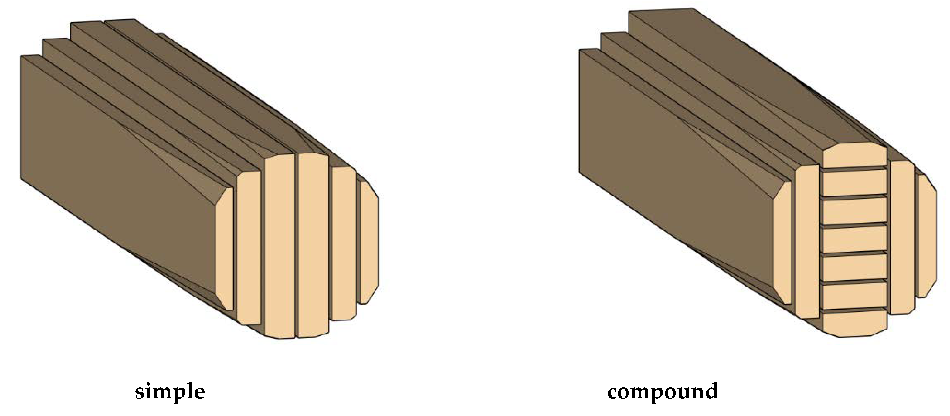
- Cutting pattern mode (Figure 5): the program must allow the use of a simple cutting pattern and a compound cutting pattern;
- A layout of the cutting pattern in relation to the center of the log: in the program, it must be possible to select a cutting pattern in which the cutting plane passes through the center of the log (Figure 6a) or the center of the log is a part of the central timber (Figure 6b). The choice of method depends on the need to remove the lower quality wood;
- The same setting can be adjusted for the compound cutting pattern: in the program, it must be possible to select a cutting pattern in which the cutting plane passes through the center of the log (Figure 7a) or the center of the log is a part of the central timber (Figure 7b). The choice of method depends on the need to remove the lower quality wood;
- Diameter of the thinner end of the log (d) (Figure 4): the program should allow adjustments between 14 and 40 cm. The program calculates this parameter when the cutting pattern is set. However, this parameter can also be entered manually;
- Timber loss due to log conicity: this value should be adjustable between 0% and 40% of the length of the upper half of the timber. This value is chosen on the basis of the qualitative sorting of the timber;
- Standard timber length: with the entered input parameters, the program calculates the exact lengths of the individual timber pieces. It allows one to select the standard timber lengths (rounded to an integer in tenths of a meter);
- Nominal dimensions of timber (Figure 8): the cutting pattern is compiled using two tables. One table is intended for vertical timber and the other for horizontal timber. The program scheme is symmetrical; the timber list begins with the log center and the numbering increases to the edge of the log. It will be possible to design the cutting pattern for 40 pieces of timber at maximum;
- Diameter of the log end (D) (the diameter of the butt end) calculated bywhere:D = L·c + d
- L: the log length in (m);
- c: the log conicity in (cm/m); and
- d: the thickness of the thinner end of the log (m);
- Number of timber pieces used in the program calculation (q): the timber in the pattern exists as a pair due to the symmetry of the cutting pattern. Depending on the method of the log center working, the first piece of timber may have a value of 1, provided that the log center is a part of the central timber. This value is automatically changed by the condition in MS Excel, which first checks the distance of the timber outer surface from the center of the log. If it is equal to the timber thickness, it writes the value 2, and if it is half the distance, it writes the value 1.
- m1: the nominal timber thickness in mm (the first of the pair); and
- m2: the nominal timber thickness in mm (the second of the pair).
- k1: the coefficient of timber reduction from drying in mm; and
- s: the cut thickness in mm;
- The timber length depends on several factors. In the first step, the program checks whether the standard timber width fits into the appropriate diameter at the appropriate position. The situation is checked by the condition bk < bl. If the condition is true, the timber length is the same as the log length. If false, the timber will be shorter than the log length or will be zero (Figure 9);
- The value of bk is calculated according to the relationwhere:bk = b + k
- b: the nominal timber width in mm; and
- k: the coefficient of timber reduction from drying in mm;
- The value of bl is calculated according to the relationif a ≤ d/2, thenand if a ≥ d/2, thenbl = √ (d2 + 4a2)where:bl = 0
- d: the diameter of the log at the narrower end in mm; and
- a: the distance of the timber outer surface from the log center in mm.
- The diameter d1 is used to find the timber length (l) in mm
- L: the log length in mm; and
- D: the diameter at the thicker end of the log in mm.
- The timber volume (VL) is calculated as followswhere:VL = l·m·b·q
- l: the timber length in m;
- m: the timber thickness in m;
- b: the timber width in m; and
- q: the number of timber pieces of the given dimensions;
- The volume of the log (Vp) is calculated from the following equation:Vp = 1/3·π·L·((D/2)2 + D/2·d/2 + (d/2)2)
- The sum of all timber volumes (Vs) is calculated as follows:Vs = ∑VL
- The volume lost in the drying process (VKq) is calculated using the following equation:
- q: the number of identical pieces of timber;
- l: the timber length in m;
- k(b): the reduction in timber width in m;
- k(m): the reduction in timber thickness in m;
- b: the timber width in m; and
- m: the timber thickness in m;
- The total volume of timber lost in the drying process is calculated as follows:VK = ∑VKq
- Sawdust volume
- mk: the timber thickness after drying in m;
- bk: the timber width after drying process in m;
- s: the cut thickness in m; and
- l: the timber length in m.
- Other volume of residues (VJ)
3. Results
4. Discussion
5. Conclusions
- We can conclude from the results that the tested prediction model fulfils the basic requirement of insensitivity to the tree species. This means that the model tested does not produce differences in the result based on the type of wood. Otherwise, it would mean either favoring or disadvantaging some kinds of wood, which would be a negative effect;
- The use of this prediction model to calculate the quantity of products from the proposed cutting pattern is appropriate because the low values of the percentage differences of the individual products were confirmed by comparing the real values of the percentages of the resulting products with the calculated values;
- In the case of timber products, the model significantly underestimates this proportion by 3.7%. The model underestimates the proportion of residues by 0.14%, but is not statistically significant. The model significantly underestimates the proportion of sawdust by 2.25%. The proposed cutting pattern for a specific log provides very precise values of the yield, based on the measured parameters and the mentioned methodology. This fact makes it possible to design an optimal cutting pattern for the log;
- The results of the statistical comparison indicate that with the decreasing quality of the input log, especially the curvature parameter of the log, the prediction model will lose its accuracy. Similarly, the prediction model does not take into account any qualitative features of the log, so it does not provide us with any information on the quality of the produced timber in its prediction;
- By assessing the results obtained, we can conclude that the prediction model is a good basis for optimizing log yields. In further developments, it has to be supplemented with a log curvature parameter. Then, it must be connected with new scanning technologies, which will supplement the prediction model with information about internal and external wood defects and these defects will be taken into account to achieve the most accurate yield optimization in terms of product quality.
Author Contributions
Funding
Acknowledgments
Conflicts of Interest
References
- Vrchota, J.; Pech, M. Readiness of Enterprises in Czech Republic to Implement Industry 4.0: Index of Industry 4.0. Appl. Sci. 2019, 9, 5405. [Google Scholar] [CrossRef] [Green Version]
- Halse, L.L.; Jæger, B. Operationalizing Industry 4.0: Understanding Barriers of Industry 4.0 and Circular Economy. In Advances in Production Management Systems. Towards Smart Production Management Systems; Ameri, F., Stecke, K., von Cieminski, G., Kiritsis, D., Eds.; Springer: Cham, Switzerland, 2019; Volume 567, pp. 135–142. [Google Scholar]
- Müller, F.; Jaeger, D.; Hanewinkel, M. Digitization in wood supply—A review on how Industry 4.0 will change the forest value chain. Comput. Electron. Agric. 2019, 162, 206–218. [Google Scholar] [CrossRef]
- Gergeľ, T.; Bucha, T.; Gejdoš, M.; Vyhnáliková, Z. Computed tomography log scanning–high technology for forestry and forest based industry. Cent. Eur. For. J. 2019, 65, 51–59. [Google Scholar]
- Steele, P.H. Factors Determining Lumber Recovery in Sawmilling; US Department of Agriculture, Forest Service, Forest Products Laboratory: Madison, WI, USA, 1984; pp. 1–8. [Google Scholar]
- Lundahl, C.G.; Grönlund, A. Increased yield in sawmills by applying alternate rotation and lateral positioning. For. Prod. J. 2010, 60, 331–338. [Google Scholar] [CrossRef]
- Lindner, B.G.; Vlok, P.J.; Wessels, C.B. Determining optimal primary sawing and ripping machine settings in the wood manufacturing chain. South. For. J. For. Sci. 2015, 77, 191–201. [Google Scholar] [CrossRef] [Green Version]
- Lin, W.; Wang, J.; Thomas, E. Development of a 3D log sawing optimization system for small sawmills in central Appalachia, US. Wood Fiber Sci. 2011, 43, 379–393. [Google Scholar]
- Geerts, J. Mathematical solution for optimising the sawing pattern of a log given its dimensions and its defect core. N. Z. J. For. Sci. 1984, 14, 124–134. [Google Scholar]
- Meier, P.; Rukki, H. Saekavade Koostamine ja Arvutamine: Õppematerjal; Tallinna Tehnikaülikooli Kirjastus: Tallinn, Estonia, 2001; pp. 1–39. [Google Scholar]
- Tudor, E.M.; Barbu, M.C.; Petutschnigg, A.; Réh, R.; Krišťák, Ľ. Analysis of Larch-Bark Capacity for Formaldehyde Removal in Wood Adhesives. Int. J. Environ. Res. Public Health 2020, 17, 764. [Google Scholar] [CrossRef] [Green Version]
- Réh, R.; Igaz, R.; Krišťák, Ľ.; Ružiak, I.; Gajtanska, M.; Božíková, M.; Kučerka, M. Functionality of Beech Bark in Adhesive Mixtures Used in Plywood and Its Effect on the Stability Associated with Material Systems. Materials 2019, 12, 1298. [Google Scholar] [CrossRef] [Green Version]
- Chiorescu, S.; Grönlund, A. The fingerprint approach: Using data generated by a 3D log scanner on debarked logs to accomplish traceability in the sawmill’s log yard. For. Prod. J. 2004, 54, 269–276. [Google Scholar]
- Thomas, R.E.; Bennett, N.D. An analysis of the differences among log scaling methods and actual log volume. For. Prod. J. 2017, 67, 250–257. [Google Scholar] [CrossRef]
- Siekański, P.; Magda, K.; Malowany, K.; Rutkiewicz, J.; Styk, A.; Krzesłowski, J.; Kowaluk, T.; Zagórski, A. On-Line Laser Triangulation Scanner for Wood Logs Surface Geometry Measurement. Sensors 2019, 19, 1074. [Google Scholar] [CrossRef] [PubMed] [Green Version]
- Bhandarkar, S.M.; Faust, T.D.; Tang, M. CATALOG: A system for detection and rendering of internal log defects using computer tomography. Mach. Vis. Appl. 1999, 11, 171–190. [Google Scholar] [CrossRef]
- Giudiceandrea, F.; Ursella, E.; Vicario, E. A high speed CT scanner for the sawmill industry. In Proceedings of the 17th International Non-Destructive Testing and Evaluation of Wood Symposium, Sopron, Hungary, 14–16 September 2011; University of West Hungary: Sopron, Hungary, 2011; pp. 105–112. [Google Scholar]
- Correa, C.A.; Maldonado, M.R.; Lozano, D.M.; Carrasco, C.A. 3D optimization of cutting patterns for logs of Pinus Radiata D. don with cylindrical defective core. In Proceedings of the 10th International Conference on Modeling, Optimization and Simulation—MOSIM’14, Nancy, France, 5–7 November 2014. [Google Scholar]
- Gazo, R.; Vanek, J.; Abdul_Massih, M.; Benes, B. A fast pith detection for computed tomography scanned hardwood logs. Comput. Electron. Agric. 2020, 170, 105107. [Google Scholar] [CrossRef]
- Stängle, S.M.; Brüchert, F.; Heikkila, A.; Usenius, T.; Usenius, A.; Sauter, U.H. Potentially increased sawmill yield from hardwoods using X-ray computed tomography for knot detection. Ann. For. Sci. 2015, 72, 57–65. [Google Scholar] [CrossRef] [Green Version]
- Longo, B.L.; Brüchert, F.; Becker, G.; Sauter, U.H. Validation of a CT knot detection algorithm on fresh Douglas-fir (Pseudotsuga menziesii (Mirb.) Franco) logs. Ann. For. Sci. 2019, 76, 28. [Google Scholar] [CrossRef] [Green Version]
- Gejdoš, M.; Lieskovský, M.; Giertliová, B.; Němec, M.; Danihelová, Z. Prices of raw-wood assortments in selected markets of central Europe and their development in the future. BioResources 2019, 14, 2995–3011. [Google Scholar]
- Potkány, M.; Gejdoš, M.; Debnár, M. Sustainable Innovation Approach for Wood Quality Evaluation in Green Business. Sustainability 2018, 10, 2984. [Google Scholar] [CrossRef] [Green Version]
- Microsoft Office Excel Help. MAX Function. 2020. Available online: https://support.office.com/en-us/article/max-function-e0012414-9ac8-4b34-9a47-73e662c08098 (accessed on 20 March 2020).
- Lopez de Lacalle, L.N.; Fernández-Larrinoa, J.; Rodríguez-Ezquerro, A.; Fernández-Valdivielso, A.; López-Blanco, R.; Azkona-Villaverde, I. On the cutting of wood for joinery applications. Proc. Inst. Mech. Eng. Part B J. Eng. Manuf. 2015, 229, 940–952. [Google Scholar] [CrossRef]
- Arnaiz-González, Á.; Fernández-Valdivielso, A.; Bustillo, A.; de Lacalle, L.L. Using artificial neural networks for the prediction of dimensional error on inclined surfaces manufactured by ball-end milling. Int. J. Adv. Manuf. Technol. 2016, 83, 847–859. [Google Scholar] [CrossRef]
- Fernández-Abia, A.I.; Barreiro, J.; Fernández-Larrinoa, J.; de Lacalle, L.L.; Fernández-Valdivielso, A.; Pereira, O.M. Behaviour of PVD coatings in the turning of austenitic stainless steels. Procedia Eng. 2013, 63, 133–141. [Google Scholar] [CrossRef] [Green Version]


| Tree Species | Markings | Diameter of Thicker End (mm) | Diameter of the Centre (mm) | Diameter of the Thinner End (mm) | Total Length (mm) |
|---|---|---|---|---|---|
| Spruce | 1.1 | 440 | 410 | 410 | 4080 |
| Spruce | 1.2 | 365 | 360 | 335 | 4090 |
| Spruce | 1.3 | 380 | 340 | 350 | 4110 |
| Beech | 2.1 | 375 | 350 | 350 | 4110 |
| Beech | 2.2 | 440 | 430 | 420 | 4120 |
| Beech | 2.3 | 395 | 390 | 380 | 4080 |
| Oak | 3.1 | 430 | 415 | 410 | 4110 |
| Oak | 3.2 | 380 | 370 | 360 | 4055 |
| Oak | 3.3 | 415 | 400 | 400 | 4060 |
© 2020 by the authors. Licensee MDPI, Basel, Switzerland. This article is an open access article distributed under the terms and conditions of the Creative Commons Attribution (CC BY) license (http://creativecommons.org/licenses/by/4.0/).
Share and Cite
Gergeľ, T.; Sedliak, M.; Bucha, T.; Oravec, M.; Slamka, M.; Pástor, M. Prediction Model of Wooden Logs Cutting Patterns and Its Efficiency in Practice. Appl. Sci. 2020, 10, 3003. https://doi.org/10.3390/app10093003
Gergeľ T, Sedliak M, Bucha T, Oravec M, Slamka M, Pástor M. Prediction Model of Wooden Logs Cutting Patterns and Its Efficiency in Practice. Applied Sciences. 2020; 10(9):3003. https://doi.org/10.3390/app10093003
Chicago/Turabian StyleGergeľ, Tomáš, Maroš Sedliak, Tomáš Bucha, Milan Oravec, Marián Slamka, and Michal Pástor. 2020. "Prediction Model of Wooden Logs Cutting Patterns and Its Efficiency in Practice" Applied Sciences 10, no. 9: 3003. https://doi.org/10.3390/app10093003
APA StyleGergeľ, T., Sedliak, M., Bucha, T., Oravec, M., Slamka, M., & Pástor, M. (2020). Prediction Model of Wooden Logs Cutting Patterns and Its Efficiency in Practice. Applied Sciences, 10(9), 3003. https://doi.org/10.3390/app10093003