Joint Torques and Tibiofemoral Joint Reaction Force in the Bodyweight “Wall Squat” Therapeutic Exercise


Abstract
Featured Applications
Abstract
1. Introduction
2. Materials and Methods
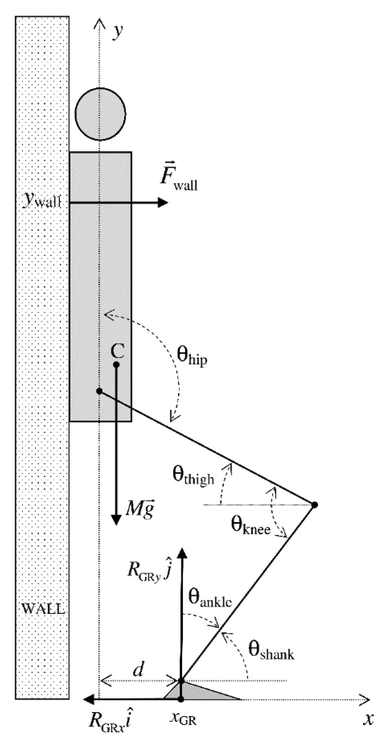
2.1. Biomechanical Modelling
2.2. Participants
2.3. Testing Session
2.4. Data Recording and Processing
2.5. Statistical Analysis
3. Results
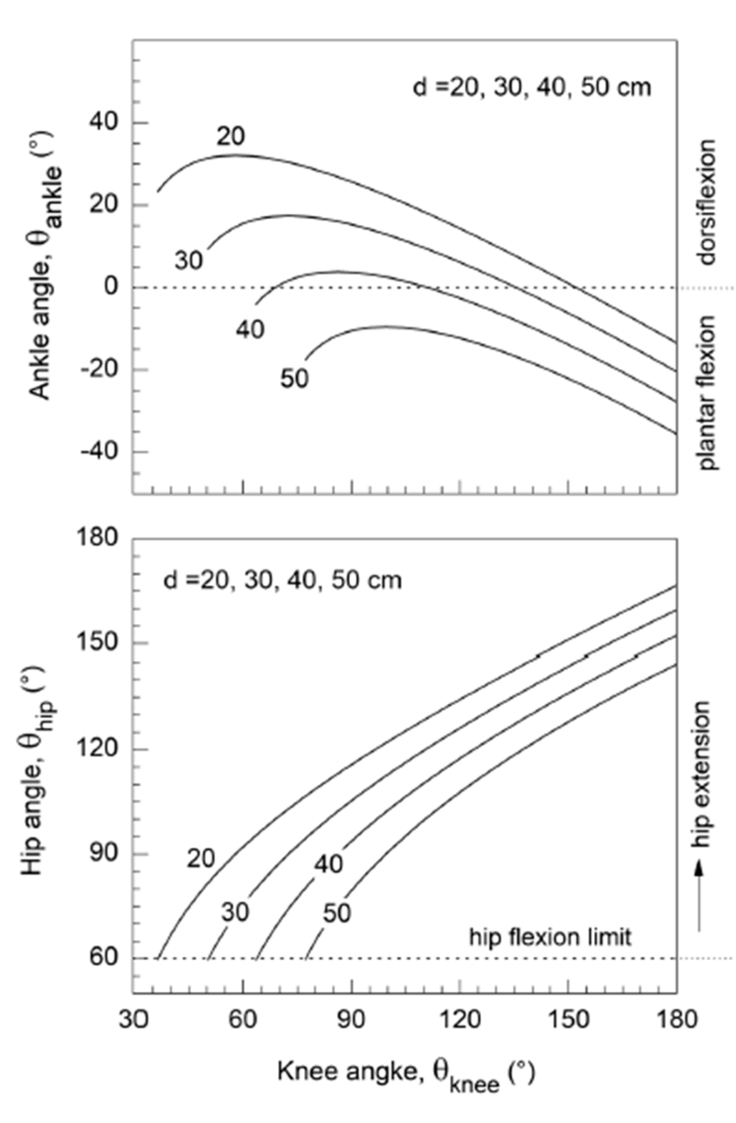
3.1. Kinematics
3.2. Ground Reaction Force
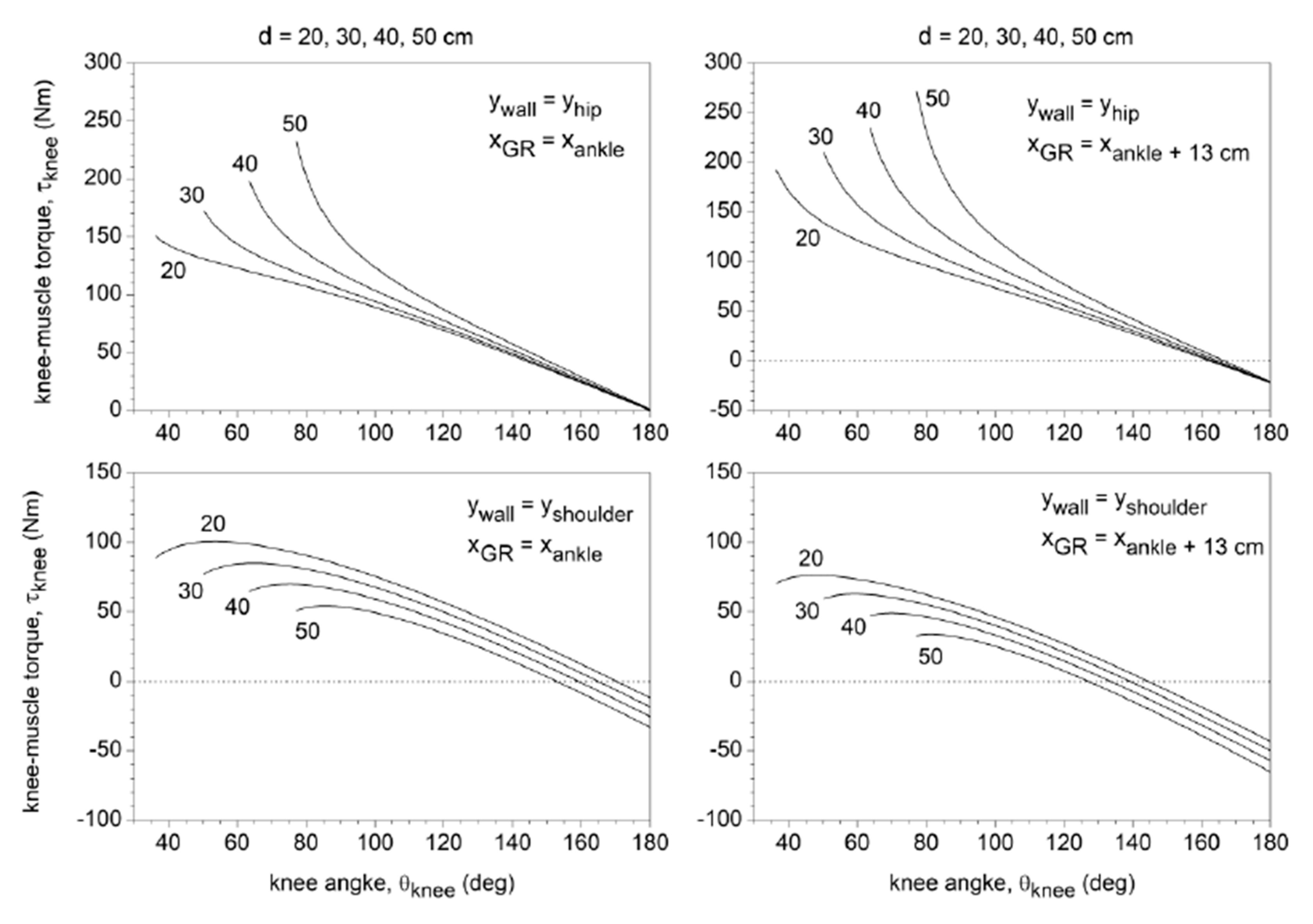
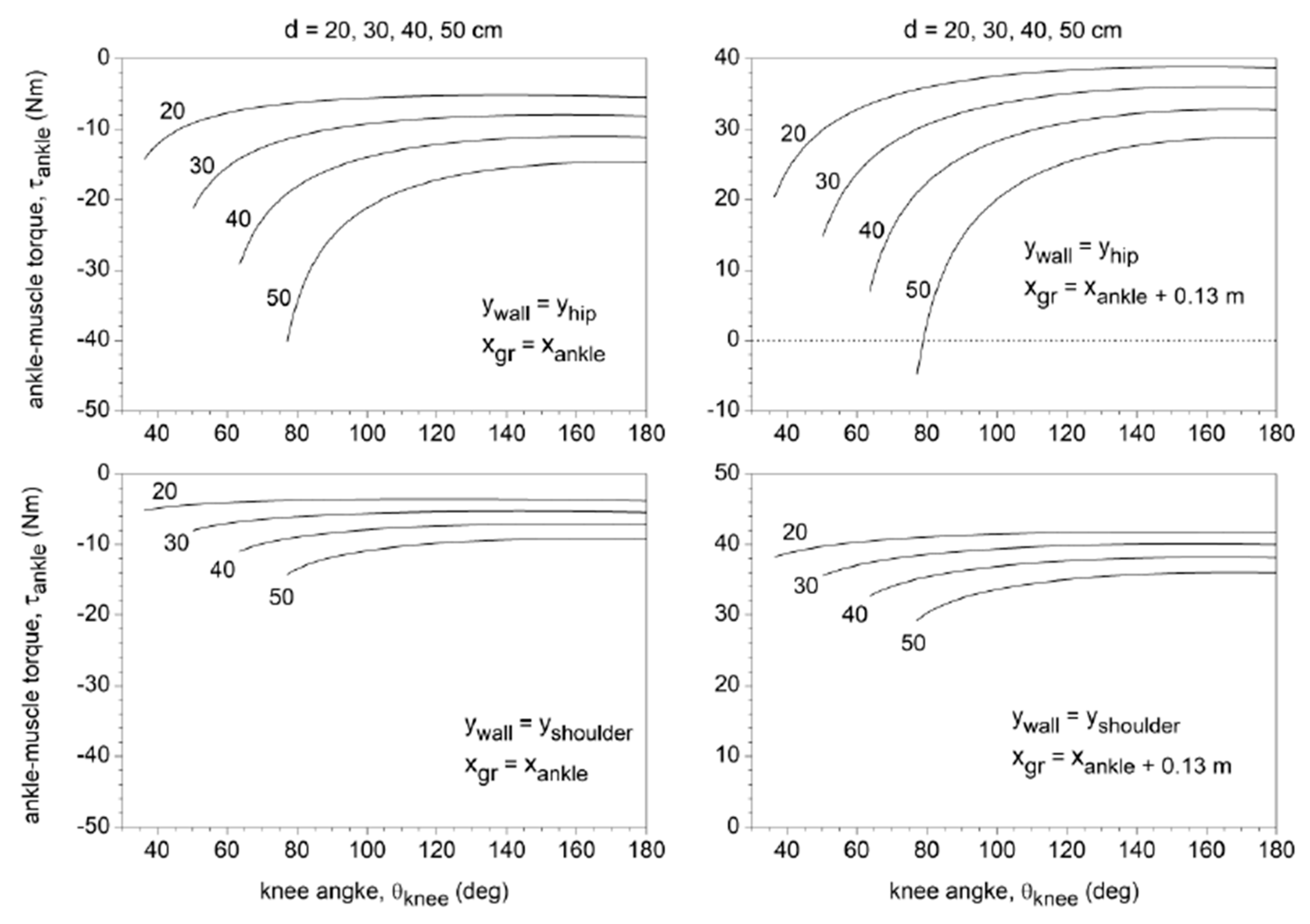
3.3. Joint Torques and TF Shear Force
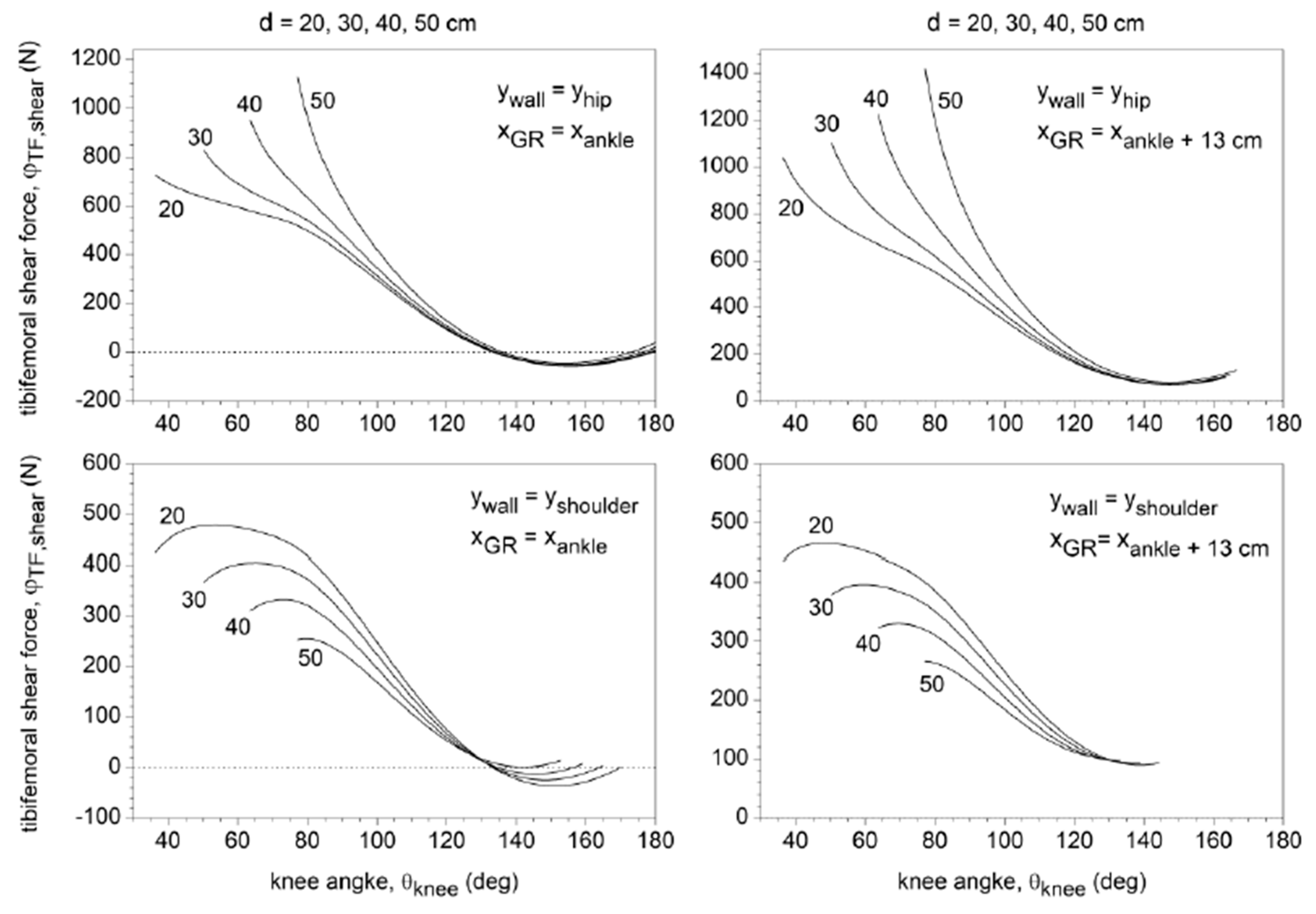
3.4. TF Shear Force
4. Discussion
5. Conclusions
Author Contributions
Funding
Conflicts of Interest
References
- Kisner, C.; Colby, L. Therapeutic Exercise: Foundations and Techniques, 6th ed.; F.A. Davis Company: Philadelphia, PA, USA, 2012; p. 836. [Google Scholar]
- Vaegter, H.B.; Lyng, K.D.; Yttereng, F.W.; Christensen, M.H.; Sørensen, M.B.; Graven-Nielsen, T. Exercise-Induced Hypoalgesia After Isometric Wall Squat Exercise: A Test-Retest Reliabilty Study. Pain Med. 2018, 20, 129–137. [Google Scholar] [CrossRef] [PubMed]
- Cho, M. The effects of modified wall squat exercises on average adults’ deep abdominal muscle thickness and lumbar stability. J. Phys. Ther. Sci. 2013, 25, 689–692. [Google Scholar] [CrossRef] [PubMed]
- Lee, Y. The influence of unstable modified wall squat exercises on the posture of female university students. J. Phys. Ther. Sci. 2015, 27, 2477–2480. [Google Scholar] [CrossRef] [PubMed]
- Goldring, N.; Wiles, J.D.; Coleman, D. The effects of isometric wall squat exercise on heart rate and blood pressure in a normotensive population. J. Sports Sci. 2014, 32, 129–136. [Google Scholar] [CrossRef] [PubMed]
- Blanpied, P. Changes in Muscle Activation During Wall Slides and Squat-Machine Exercise. J. Sport Rehabil. 1999, 8, 123–134. [Google Scholar] [CrossRef]
- Biscarini, A.; Benvenuti, P.; Botti, F.M.; Mastrandrea, F.; Zanuso, S. Modelling the joint torques and loadings during squatting at the Smith machine. J. Sports Sci. 2011, 29, 457–469. [Google Scholar] [CrossRef] [PubMed]
- Biscarini, A.; Busti, D.; Calandra, A.; Contemori, S. The “supine bridge” therapeutic exercise: Determination of joint torques by means of biomechanical modelling and technologies. J. Mech. Med. Biol. 2017, 17, 1750104-1–1750104-16. [Google Scholar] [CrossRef]
- Winter, D.A. Biomechanics and Motor Control of Human Movement, 3rd ed.; Wiley: New York, NY, USA, 2005; pp. 60–64. [Google Scholar]
- De Leva, P. Adjustments to Zatisiorsky–Seluyanov’s segment inertia parameters. J. Biomech. 1996, 29, 1223–1230. [Google Scholar] [CrossRef]
- Butler, D.L.; Noyes, F.R.; Grood, E.S. Ligamentous restraints to anterior-posterior drawer in the human knee: A biomechanical study. J. Bone Jt. Surg. 1980, 62, 259–270. [Google Scholar] [CrossRef]
- Contemori, S.; Biscarini, A.; Botti, F.M.; Busti, D.; Panichi, R.; Pettorossi, V.E. Sensorimotor Control of the Shoulder in Professional Volleyball Players with Isolated Infraspinatus Muscle Atrophy. J. Sport Rehabil. 2018, 27, 371–379. [Google Scholar] [CrossRef] [PubMed]
- Biscarini, A.; Benvenuti, P.; Botti, F.M.; Brunetti, A.; Brunetti, O.; Pettorossi, V.E. Voluntary enhanced cocontraction of hamstring muscles during open kinetic chain leg extension exercise: Its potential unloading effect on the anterior cruciate ligament. Am. J. Sports Med. 2014, 42, 2103–2112. [Google Scholar] [CrossRef] [PubMed]
- Biscarini, A.; Contemori, S.; Busti, D.; Botti, F.M.; Pettorossi, V.E. Knee flexion with quadriceps cocontraction: A new therapeutic exercise for the early stage of ACL rehabilitation. J. Biomech. 2016, 49, 3855–3860. [Google Scholar] [CrossRef] [PubMed]
- Dvir, Z. Isokinetic, 2nd ed.; Churchill Livingstone: Edimburgh, UK, 2004. [Google Scholar]
- Neumann, D.A. Kinesiology of the Musculoskeletal System, 2nd ed.; Mosby: St. Louis, MO, USA, 2010; pp. 408, 500. [Google Scholar]
- Panjabi, M.M. The stabilizing system of the spine. Part II. Neutral zone and instability hypothesis. J. Spinal Disord. 1992, 5, 390–396. [Google Scholar] [CrossRef] [PubMed]
- Knapik, J.J.; Wright, J.E.; Mawdsley, R.H.; Braun, J. Isometric, isotonic, and isokinetic torque variations in four muscle groups through a range of joint motion. Phys. Ther. 1983, 63, 938–947. [Google Scholar] [CrossRef] [PubMed]
- Pandy, M.G.; Sasaki, K.; Kim, S. A three-dimensional musculoskeletal model of the human knee joint. Part 1: Theoretical construct. Comput. Methods Biomech. Biomed. Eng. 1998, 1, 87–108. [Google Scholar] [CrossRef] [PubMed]
- Shelburne, K.B.; Pandy, M.G. A musculoskeletal model of the knee for evaluating ligament forces during isometric contractions. J. Biomech. 1997, 30, 163–176. [Google Scholar] [CrossRef]
- Zheng, N.; Fleisig, G.S.; Escamilla, R.F.; Barrentine, S.W. An analytical model of the knee for estimation of internal forces during exercise. J. Biomech. 1998, 31, 963–967. [Google Scholar] [CrossRef]
- Escamilla, R.F.; Zheng, N.; Macleod, T.D.; Edwards, W.B.; Imamura, R.; Hreljac, A.; Fleisig, G.S.; Wilk, K.E.; Moorman, C.T.; Andrews, J.R. Patellofemoral joint force and stress during the wall squat and one-leg squat. Med. Sci. Sports Exerc. 2009, 41, 879–888. [Google Scholar] [CrossRef] [PubMed]
- Escamilla, R.F.; Macleod, T.D.; Wilk, K.E.; Paulos, L.; Andrews, J.R. Cruciate ligament loading during common knee rehabilitation exercises. Proc. Inst. Mech. Eng. Part H 2012, 226, 670–680. [Google Scholar] [CrossRef] [PubMed]
- Biscarini, A.; Botti, F.M.; Pettorossi, V.E. Selective contribution of each hamstring muscle to anterior cruciate ligament protection and tibiofemoral joint stability in leg-extension exercise: A simulation study. Eur. J. Appl. Physiol. 2013, 113, 2263–2273. [Google Scholar] [CrossRef] [PubMed]


| Torque Type | Maximum Torque | Conditions for Maximum Torque | Peak Isokinetic Torque of Males (Females) | |||
|---|---|---|---|---|---|---|
| Knee Angle | Distance d | Type of Support | Body Weight at Forefoot/Rearfoot | |||
| Hip extension torque | 130 Nm | 80° | 50 cm | scapular | forefoot | 177 Nm (110 Nm) |
| Knee extension torque | 250 Nm | 80° | 50 cm | pelvic | forefoot | 268 Nm (176 Nm) |
| Knee flexion torque | 65 Nm | 0° | 50 cm | scapular | forefoot | 171 Nm (110 Nm) |
| Ankle plantar-flexion torque | 40 Nm | 0° | 50 cm | scapular/pelvic | forefoot | 171 Nm (108 Nm) |
| Ankle dorsi-flexion torque | 40 Nm | 80° | 20 cm | pelvic | rearfoot | 33 Nm (26 Nm) |
© 2020 by the authors. Licensee MDPI, Basel, Switzerland. This article is an open access article distributed under the terms and conditions of the Creative Commons Attribution (CC BY) license (http://creativecommons.org/licenses/by/4.0/).
Share and Cite
Biscarini, A.; Contemori, S.; Dieni, C.V.; Panichi, R. Joint Torques and Tibiofemoral Joint Reaction Force in the Bodyweight “Wall Squat” Therapeutic Exercise. Appl. Sci. 2020, 10, 3019. https://doi.org/10.3390/app10093019
Biscarini A, Contemori S, Dieni CV, Panichi R. Joint Torques and Tibiofemoral Joint Reaction Force in the Bodyweight “Wall Squat” Therapeutic Exercise. Applied Sciences. 2020; 10(9):3019. https://doi.org/10.3390/app10093019
Chicago/Turabian StyleBiscarini, Andrea, Samuele Contemori, Cristina V. Dieni, and Roberto Panichi. 2020. "Joint Torques and Tibiofemoral Joint Reaction Force in the Bodyweight “Wall Squat” Therapeutic Exercise" Applied Sciences 10, no. 9: 3019. https://doi.org/10.3390/app10093019
APA StyleBiscarini, A., Contemori, S., Dieni, C. V., & Panichi, R. (2020). Joint Torques and Tibiofemoral Joint Reaction Force in the Bodyweight “Wall Squat” Therapeutic Exercise. Applied Sciences, 10(9), 3019. https://doi.org/10.3390/app10093019