Article

Analysis on Tunnel Field-Effect Transistor with Asymmetric Spacer

1
Inter-University Semiconductor Research Center, Department of Electrical and with the Department of Computer Engineering, Seoul National University, Seoul 08826, Korea
2
Department of Electrical Engineering, Inha University, Incheon 22212, Korea
*
Author to whom correspondence should be addressed.
Appl. Sci. 2020, 10(9), 3054; https://doi.org/10.3390/app10093054
Submission received: 26 March 2020 / Revised: 18 April 2020 / Accepted: 21 April 2020 / Published: 27 April 2020
(This article belongs to the Special Issue New Aspects of Si-Based Material and Device)

Abstract

:
Tunnel field-effect transistor (Tunnel FET) with asymmetric spacer is proposed to obtain high on-current and reduced inverter delay simultaneously. In order to analyze the proposed Tunnel FET, electrical characteristics are evaluated by technology computer-aided design (TCAD) simulations with calibrated tunneling model parameters. The impact of the spacer κ values on tunneling rate is investigated with the symmetric spacer. As the κ values of the spacer increase, the on-current becomes enhanced since tunneling probabilities are increased by the fringing field through the spacer. However, on the drain-side, that fringing field through the drain-side spacer increases ambipolar current and gate-to-drain capacitance, which degrades leakage property and switching response. Therefore, the drain-side low-κ spacer, which makes the low fringing field, is adapted asymmetrically with the source-side high-κ spacer. This asymmetric spacer results in the reduction of gate-to-drain capacitance and switching delay with the improved on-current induced by the source-side high-κ spacer.

1. Introduction

Over the past several decades, transistor dimensions have been continuously scaled down to make switching speed faster and to increase integration density, in accordance with Moore’s Law [1]. However, device scaling induces many critical issues, such as short-channel effects (SCEs) and high leakage current. To overcome these challenges, conventional planar metal oxide semiconductor field-effect-transistor (MOSFET) is changed to multi-gated (MG) FETs (e.g., FinFETs), which have better gate controllability, resulting in high on/off current ratio with good SCEs [2]. Recently, various device architectures have been studied as the next generation devices beyond FinFET [3,4,5,6,7,8,9,10,11,12,13]. One of the key concerns is to have steep subthreshold swing (SS), which makes low supply voltage operations, because most portable electronic devices demand low power consumption to keep them operating for a long time. Tunnel field-effect transistor (Tunnel FET) is one of candidates for SS of sub-60 mV/dec. Tunnel FETs use band-to-band tunneling (BTBT) as a carrier injection mechanism in contrast to MOSFETs, which have SS limitation (>60 mV/dec) by thermionic emission at room temperature. An n-type tunnel FET consists of a p-type source, intrinsic channel, and n-type drain and, thus, it is compatible with a conventional MOSFET process, since only the source dopant type is changed. Although it has a low leakage current and temperature sensitivity compared to MOSFETs, it has, in addition, smaller on-current due to high tunneling resistance by a small tunneling region. Therefore, to boost tunneling current, many researchers have proposed using low bandgap material, such as silicon-germanium and III-IV compound materials, pocket doping techniques, and line-tunneling [14,15,16,17,18,19,20,21]. Another problem is that ambipolar current flowing from channel to drain by tunneling at off-state causes an increase of power consumption [22]. Accordingly, many groups who are studying tunnel FETs have applied the underlap junction between gate and drain and low drain doping to suppress ambipolar current.
Here, a silicon tunnel FET with high- and low-κ spacers on source- and drain-side, respectively, is proposed with line-tunneling to improve the on/off current and switching speed. In general, using a high-κ spacer in the conventional tunnel FET (i.e., there is no line-tunneling) is not an effective solution to improve on-current, because the fringing field makes the source energy band depleted, leading to high tunneling resistance [23,24]. That’s why additional source-to-channel junction optimization or low-κ spacer are required to improve the tunneling current. On the contrary, in tunnel FET with line-tunneling, fringing field effects improve the tunneling current without any junction optimization. This is because the area underneath the spacer is not source, but an epitaxially grown silicon channel region. Therefore, the higher fringing field is applied, the larger BTBT is generated between the channel and source region. However, in spite of the line-tunneling scheme, the high-κ spacer approach, unfortunately, degrades gate-to-drain capacitance by a higher fringing field, which affects poor switching characteristics. That is why the low-κ spacer is intentionally formed on the drain-side as asymmetric spacer. Consequently, the proposed architecture gives better alternating current (AC) switching characteristics by increasing on-current and decreasing gate-to-drain capacitance, simultaneously. In addition, the process integration for the asymmetric spacer is introduced in terms of process feasibility.

2. Device Structure and Parameters

Figure 1 shows the silicon tunnel FET structure used in the simulations. Double gate and tunnel region underneath the gates are adapted to enhance gate controllability and tunneling current drivability. Tunnel region thickness (4 nm) and source overlap length (20 nm) are used, respectively.
In addition, equivalent oxide thickness (EOT) of 1 nm and body thickness of 20 nm are applied to assume high-κ dielectric and double gate structure. The drain is underlapped with the gates to suppress ambipolar current at off-state and it can be easily formed with conventional self-align process. Other detailed parameters used in the technology computer-aided design (TCAD) simulations are described in Table 1. Among the parameters, only spacer thickness and dielectric constant are variable to optimize the electrical performances of the tunnel FET. All device evaluations are performed by commercial tools of SentaurusTM (Synopsys, Mountain View, CA, USA) [25]. For accurate analysis on the tunneling current, the dynamic nonlocal BTBT model is activated in the whole regions, and used with experimentally calibrated Kane’s parameters, which are F0 = 1 V/m and P = 2.5 for indirect BTBT, ASi = 4 × 1014 cm−3·s−1 and BSi = 9.9 × 10⁶ V·cm−1, respectively [26,27]. Furthermore, the Slotboom model is applied to consider the impact of heavy doping on bandgap narrowing in the source region.
Moreover, fermi statistics, drift-diffusion, and the Shockley–Read–Hall recombination model are also used. However, trap-assisted tunneling and gate leakage current are ignored for this work because it is focused on the effects of the asymmetric spacer technique.

3. Results and Discussions

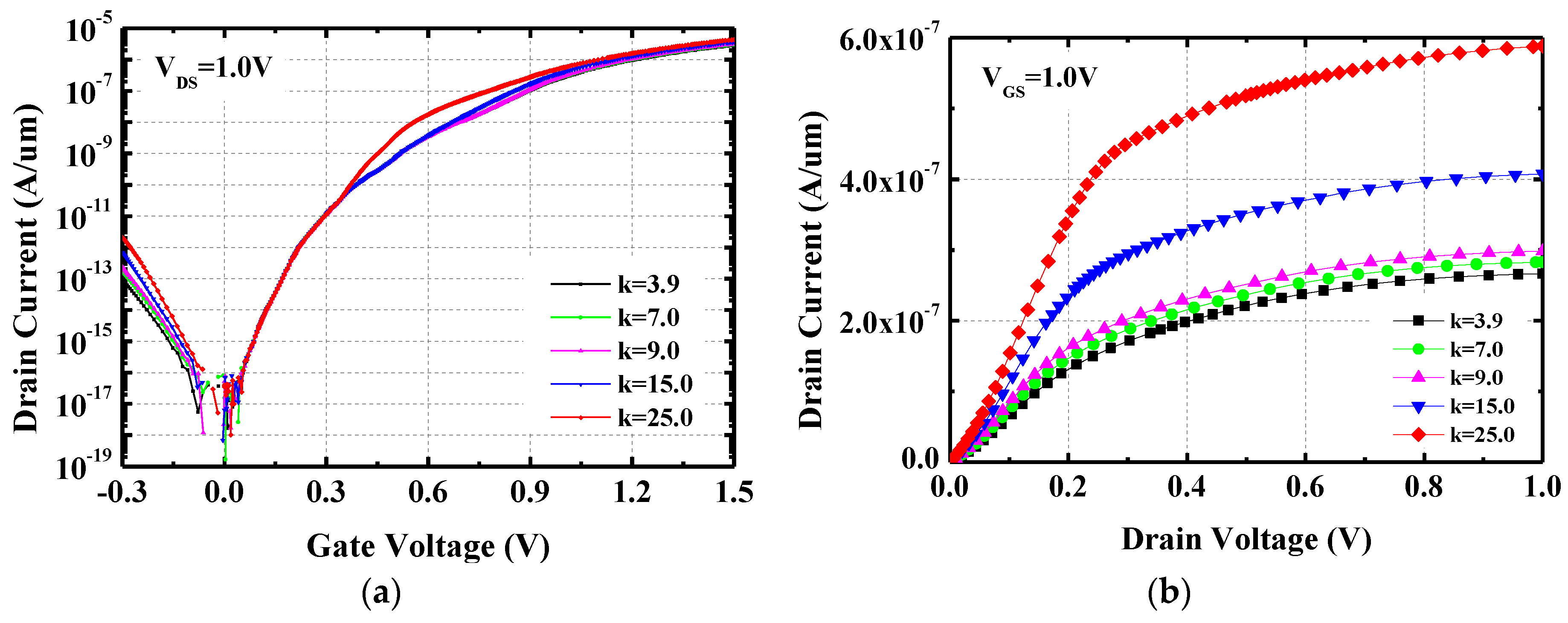
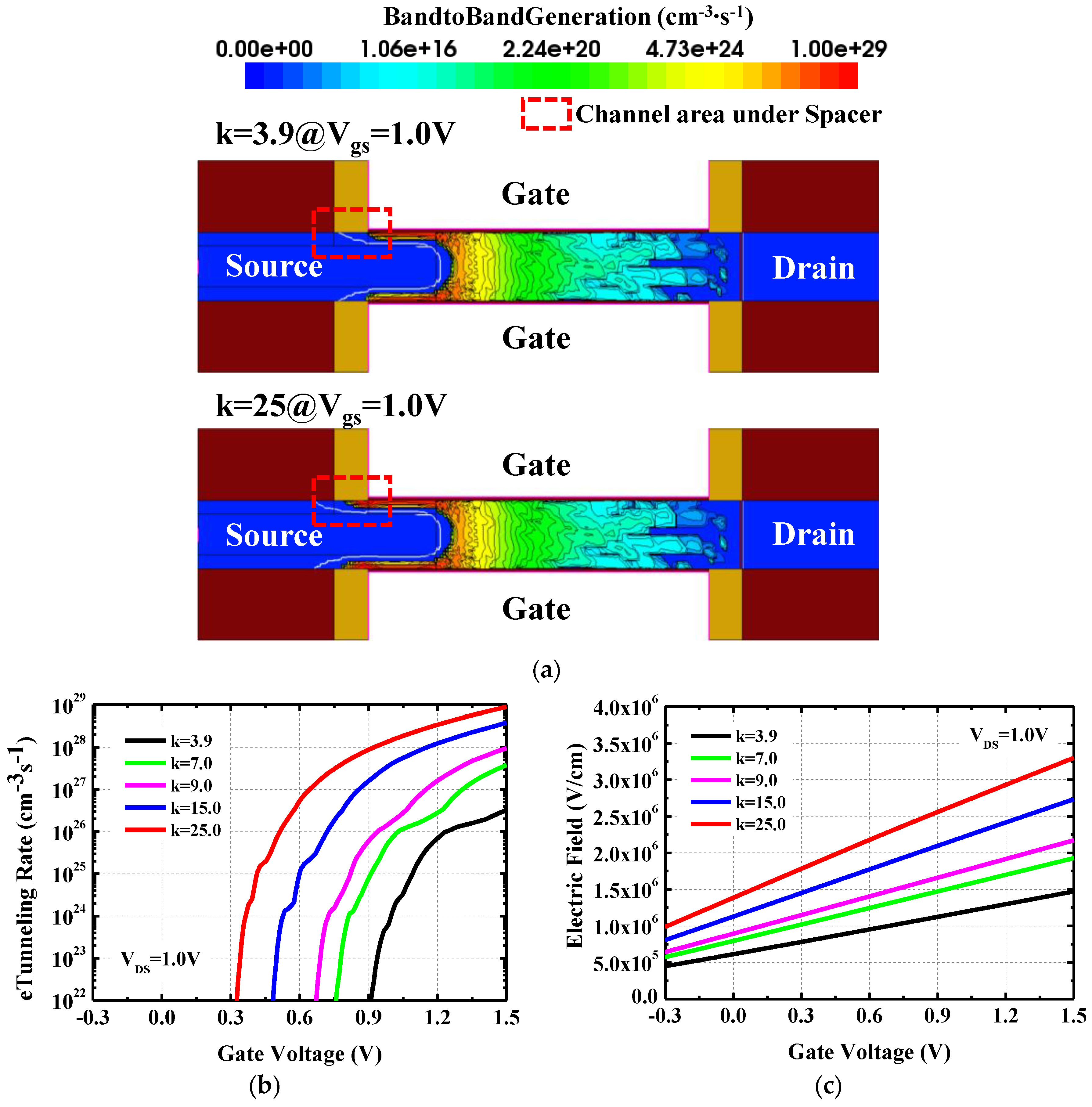
Figure 2a shows the transfer characteristics with different κ values of spacers while keeping their thickness of 10 nm. The κ values of spacers are 3.9, 7.0, 9.0, 15.0, and 25.0, which correspond to SiO2, Si3N4, Al2O3, Y2O3, and HfO2, respectively [28]. In the subthreshold region (0.0 V < VGS < 0.35 V), drain current is independent of κ values because tunneling mainly occurs between the source and tunnel region under the gate, without the effects of the fringing field through spacers. From VGS = 0.35 V, drain current starts to increase with increasing κ value. Improved current drivability can be also observed in the output characteristics as shown in Figure 2b. At VDS = 1.0 V, drain current with the spacer κ = 25.0 is enhanced more than two times compared to that with the spacer κ = 3.9. In order to check the performance improvement by high-κ spacer, BTBT rates are analyzed in the channel region underneath the spacer. Figure 3a describes the two-dimensional (2D) contour on the electron tunneling rate with the spacer of κ = 3.9 and 25 at VDS/VGS = 1.0 V/1.0 V. In case of κ = 3.9, the tunneling occurrence is negligible in the channel under the spacer region (dashed red square). That means silicon oxide does not give strong fringing field enough to improve tunneling probabilities. On the other hand, high tunneling rates can be seen by increasing the fringing field under the spacer region when the spacer of κ = 25 is used. Figure 3b indicates the averaged electron tunneling rate in the specific region under the spacer. In case of κ = 25, tunneling induced by the fringing field starts to occur from VGS = 0.31 V and continues to increase.
However, when κ values become smaller, tunneling is generated by the fringing field at the larger VGS. For κ = 3.9, it even starts from VGS = 0.9 V by the low fringing field. The difference of the tunneling turn-on voltage between κ = 3.9 and κ = 25 is almost 0.6 V. Based on these results, it is obvious that high-κ spacer is more suitable for low power and high performance devices. Averaged electric fields under the spacer are also checked according to different κ values in Figure 3c, where the electric fields linearly increase as a function of VGS, regardless of κ values. Compared to the electric field with κ = 3.9, the absolute electric field is more than doubled for κ = 25, leading to higher current drivability.
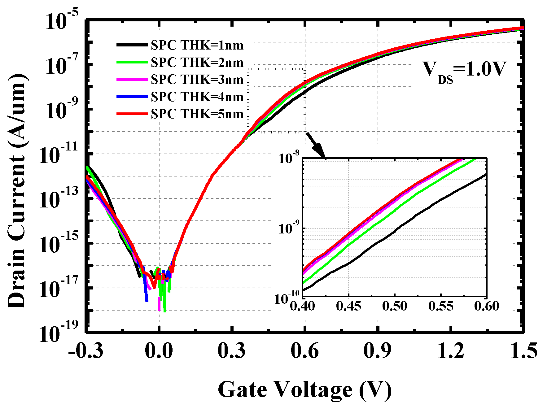
Although the impacts of the spacer κ values on the electrical characteristics of the proposed tunnel FET is studied with the fixed spacer thickness of 10 nm, the effects of the spacer thickness variation should be evaluated when considering the process feasibility. Typical high-κ materials are formed by using atomic layer deposition (ALD), which is a thin-film deposition technique based on the sequential use of a gas phase chemical process. Since the ALD is a very time-consuming process, it has been generally considered for thin film less than 10 nm. If the thick spacer is required for high fringing field, it would be one of the most serious obstacles against mass production. Therefore, the sensitivities on the reduction of the spacer thickness are simulated for thickness optimization. Figure 4 shows the transfer characteristics with various spacer thicknesses. As the thickness increases, the drain current is improved from VGS = 0.35 V by the increased fringing field through the spacer and the improvement is saturated from thicker than 3 nm. It means that a too thick spacer is not necessary to get the high fringing field, and it is advantageous to use the ALD process.
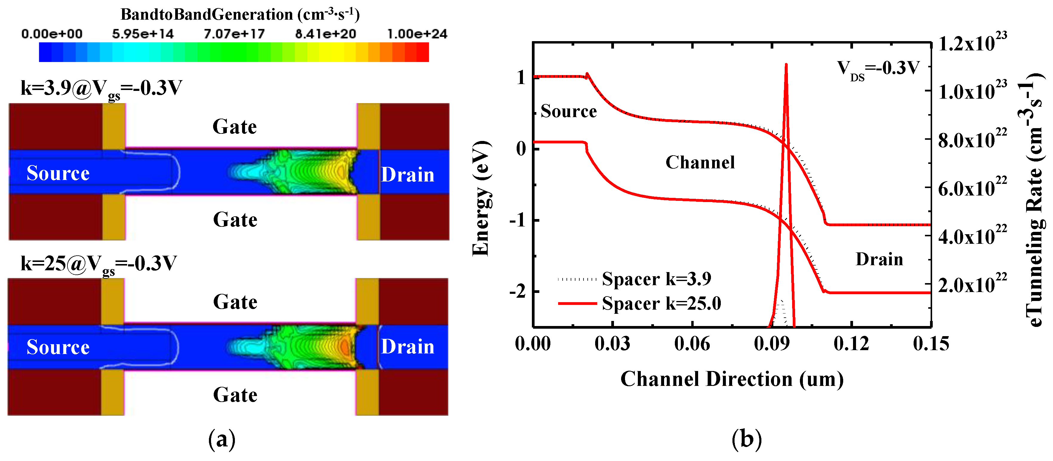
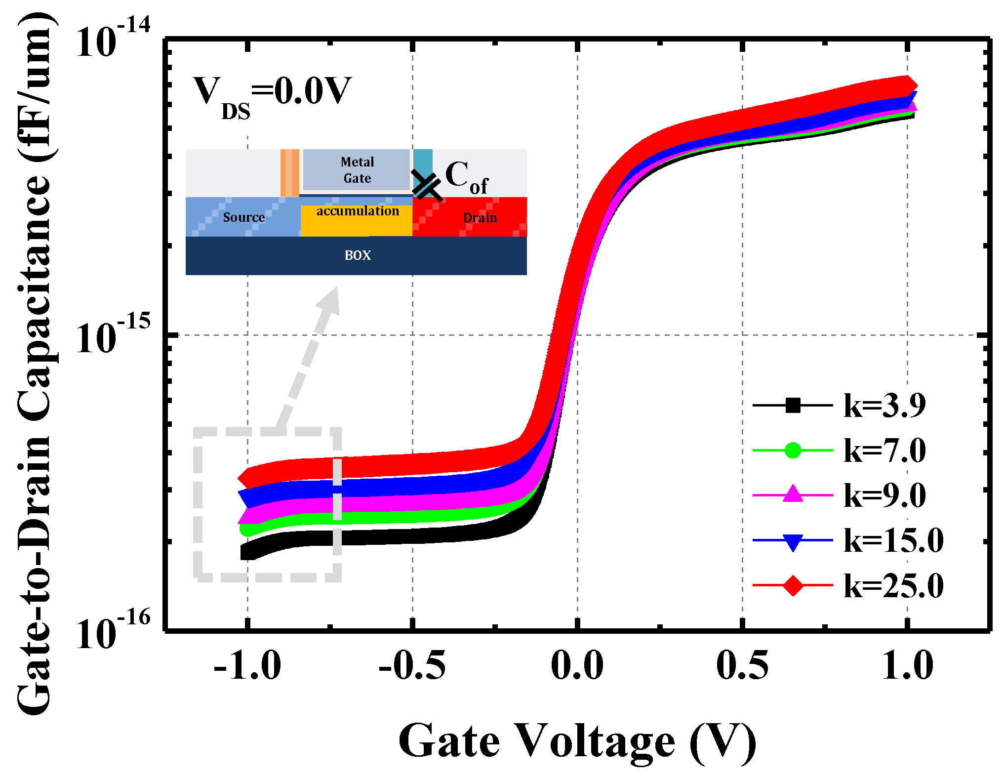
However, there are disadvantages when the high-κ spacer is applied. First, ambipolar current becomes increased due to the enhanced fringing field between gate and drain as well as between gate and source. Thus, with the larger κ values of the spacer, both on-current and ambipolar current are increased simultaneously (Figure 2a) although the drain-side underlap is used. Figure 5a shows the 2D contour on electron tunneling rate (off-state) with the spacer of κ = 3.9 and 25 at VDS/VGS = 1.0 V/−0.3 V. Compared to κ = 3.9, more electron tunneling is generated between the channel and the drain for κ = 25. The amount of the increased tunneling is around ten times in the case of the high-κ spacer (Figure 5b). Second, gate-to-drain Miller capacitance gets increasing due to the enhanced fringing field by using high-κ spacer. In tunnel FETs, the AC performance is limited by Miller capacitance effects, which induce voltage overshoot and undershoot in transient responses, unlike conventional MOSFETs [29]. It causes severe inverter delay. Therefore, the gate-to-drain capacitance is checked with respect to VGS for the different κ values of the drain-side spacer in Figure 6. To evaluate the impacts on the different κ values, the gate-to-drain capacitance is separated into each capacitance component. Except for inversion capacitance, the gate-to-drain capacitance consists of inner-fringing, outer-fringing, and direct overlap capacitance as parasitic capacitances. However, in this study, ideal junction is assumed so that direct overlap capacitance can be ignored. Hence, only the outer-fringing capacitance related to the κ values can be extracted when the channel is in accumulation (VGS = −1.0 V).
This is because the inner-fringing capacitance component can be removed by the accumulation charge layer. In the case of the spacer with κ = 25, the outer-fringing capacitance goes up by 78% compared to κ = 3.9, and the increase of this parasitic capacitance makes the switching characteristics worse.
To improve the inverter delay caused by the large gate-to-drain capacitance, the tunnel FET with asymmetric spacers is proposed. The tunnel FET has the source-side high-κ spacer to boost the on-current, whereas the low-κ spacer is formed on the drain-side to decrease the ambipolar current and the outer-fringing capacitance. Figure 7a shows the gate-to-drain capacitance characteristics with the symmetric high-κ spacer (κ = 25) and the asymmetric high/low-κ spacer (κ = 25/3.9). It is clearly shown that the outer-fringing capacitance decreases due to the reduced dielectric constant with the negligible effects on the source-side. In terms of the switching speed, inverter characteristics are analyzed with the symmetric and the asymmetric spacers, as shown in Figure 7b. Through transient simulations, the falling delay, which is defined by the time difference between input and output voltages at half supply voltage, is extracted as the indicator of an inverter response. As a result, each falling delay is 0.38 ns, 0.20 ns, and 0.18 ns for the symmetric low-κ spacer (κ = 3.9), the symmetric high-κ spacer (κ = 25), and the asymmetric high/low-κ spacer (κ = 25/3.9). By using the symmetric high-κ spacer, switching characteristics get improved by 47% due to the on-current enhancement.
Furthermore, the additional 10% improvement is achieved by the reduced gate-to-drain capacitance using the drain-side low-κ spacer.
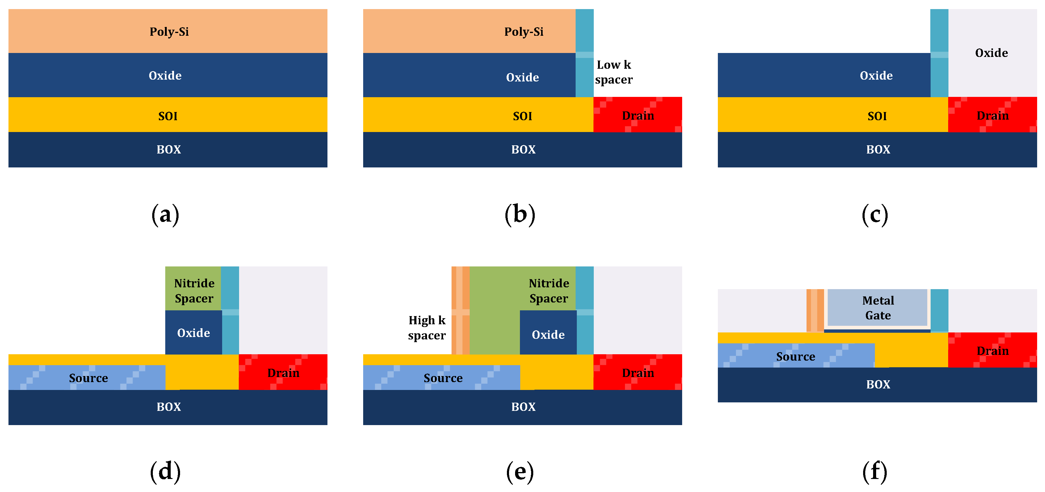
The proposed tunnel FET structure can be integrated as shown in Figure 8. First, oxide/poly-Si are sequentially deposited on silicon-on-insulator (SOI) wafer for the asymmetric spacer process (Figure 8a). After the drain-side is opened by photolithography and etching, the low-κ spacer is formed using deposition and etching. Then, self-aligned drain is defined using ion implantation process (Figure 8b). To passivate the drain side during subsequent processes, oxide is deposited on the whole region and the oxide planarization is performed by the chemical mechanical polishing (CMP) process. For the line tunneling region under a part of gate region, nitride spacer is formed on the oxide as a hard mask after the poly-Si is fully removed by using chemical etchant (Figure 8c). The oxide and partial SOI etching are carried out in sequence, and ion is implanted for the source region. On the partially etched SOI region, the selective epitaxy growth (SEG) layer, which can enhance tunneling current, can be deposited without doping (Figure 8d). After that, dopant activation is adapted and nitride spacer formation is applied again, which can determine the line tunneling area with self-alignment. Then, source-side high-κ spacer is formed to boost the tunneling current (Figure 8e), and oxide is deposited and planarized as interlayer dielectric (ILD). Finally, nitride and oxide are selectively etched out and replaced with ALD interfacial oxide, high-κ insulator, and metal gate (Figure 8f). Back-end-of-line (BEOL) flows are skipped because it is the same as the conventional complementary MOS (CMOS) process.

4. Conclusions

In this study, the tunnel FET with asymmetric spacers is proposed and analyzed compared to that with the symmetric spacer by using TCAD simulations. Although the high-κ spacer gives a large fringing field and improves on-current, there are drawbacks, such as the increase of ambipolar current and gate-to-drain capacitance. In order to solve these disadvantages, the asymmetric spacer is applied and it can reduce ambipolar current and gate-to-drain capacitance by mitigating the fringing field between the gate and drain. As a result, the tunnel FET with asymmetric spacers can improve the switching characteristics by 52%. In addition, in terms of process feasibility, the fabrication flow of the proposed tunnel FET is introduced, considering CMOS compatibility.

Author Contributions

Conceptualization, H.W.K.; data curation, H.W.K.; investigation, H.W.K.; writing of the original draft preparation, H.W.K.; writing of review and editing, H.W.K. and D.K. All authors have read and agreed to the published version of the manuscript.

Funding

This research received no external funding.

Conflicts of Interest

The authors declare no conflict of interest.

References

  1. White, M.; Chen, Y. Scaled CMOS technology reliability users guide. JPL Publ. 2008, 3, 8. [Google Scholar]
  2. Razavieh, A.; Zeitzoff, P.; Nowak, E.J. Challenges and Limitations of CMOS Scaling for FinFET and beyond Architectures. IEEE Trans. Nanotechnol. 2019, 18, 999–1004. [Google Scholar] [CrossRef]
  3. Choi, W.Y.; Park, B.G.; Lee, J.D.; Liu, T.J.K. Tunneling field-effect transistors (TFETs) with subthreshold swing (SS) less than 60 mV/dec. IEEE Electron Device Lett. 2007, 28, 743–745. [Google Scholar] [CrossRef]
  4. Boucart, K.; Ionescu, A.M. Double-gate tunnel FET with high-κ gate dielectric. IEEE Trans. Electron Devices 2007, 54, 1725–1733. [Google Scholar] [CrossRef]
  5. Kwon, D.; Cheema, S.; Lin, Y.K.; Liao, Y.H.; Chatterjee, K.; Tan, A.J.; Hu, C.; Salahuddin, S. Near Threshold Capacitance Matching in a Negative Capacitance FET with 1 nm Effective Oxide Thickness Gate Stack. IEEE Electron Device Lett. 2020, 41, 179–182. [Google Scholar] [CrossRef]
  6. Salahuddin, S.; Datta, S. Use of negative capacitance to provide voltage amplification for low power nanoscale devices. Nano Lett. 2008, 8, 405–410. [Google Scholar] [CrossRef] [PubMed]
  7. Seabaugh, A.C.; Zhang, Q. Low-voltage tunnel transistors for beyond CMOS logic. Proc. IEEE 2010, 98, 2095–2110. [Google Scholar] [CrossRef]
  8. Khan, A.I.; Yeung, C.W.; Hu, C.; Salahuddin, S. Ferroelectric negative capacitance MOSFET: Capacitance tuning & antiferroelectric operation. In Proceedings of the Technical Digest - International Electron Devices Meeting, IEDM, Washington, DC, USA, 5–7 December 2011. [Google Scholar]
  9. Ionescu, A.M.; Riel, H. Tunnel field-effect transistors as energy-efficient electronic switches. Nature 2011, 479, 329–337. [Google Scholar] [CrossRef] [PubMed]
  10. Ghosh, B.; Akram, M.W. Junctionless tunnel field effect transistor. IEEE Electron Device Lett. 2013, 34, 584–586. [Google Scholar] [CrossRef]
  11. Kim, H.W.; Kim, J.P.; Kim, S.W.; Sun, M.C.; Kim, G.; Kim, J.H.; Park, E.; Kim, H.; Park, B.G. Schottky barrier tunnel field-effect transistor using spacer technique. J. Semicond. Technol. Sci. 2014, 14, 572–578. [Google Scholar] [CrossRef]
  12. Avci, U.E.; Morris, D.H.; Young, I.A. Tunnel field-effect transistors: Prospects and challenges. IEEE J. Electron Devices Soc. 2015, 3, 88–95. [Google Scholar] [CrossRef]
  13. Pahwa, G.; Dutta, T.; Agarwal, A.; Chauhan, Y.S. Physical Insights on Negative Capacitance Transistors in Nonhysteresis and Hysteresis Regimes: MFMIS Versus MFIS Structures. IEEE Trans. Electron Devices 2018, 65, 867–873. [Google Scholar] [CrossRef]
  14. Bhuwalka, K.K.; Schulze, J.; Eisele, I. Performance enhancement of vertical tunnel field-effect transistor with SiGe in the δp+ layer. Jpn. J. Appl. Phys. Part 1 Regul. Pap. Short Notes Rev. Pap. 2004, 43, 4073–4078. [Google Scholar] [CrossRef]
  15. Zhang, Q.; Fang, T.; Xing, H.; Seabaugh, A.; Jena, D. Graphene nanoribbon tunnel transistors. IEEE Electron Device Lett. 2008, 29, 1344–1346. [Google Scholar] [CrossRef]
  16. Jhaveri, R.; Nagavarapu, V.; Woo, J.C.S. Effect of pocket doping and annealing schemes on the source-pocket tunnel field-effect Transistor. IEEE Trans. Electron Devices 2011, 58, 80–86. [Google Scholar] [CrossRef]
  17. Kim, S.H.; Agarwal, S.; Jacobson, Z.A.; Matheu, P.; Hu, C.; Liu, T.J.K. Tunnel field effect transistor with raised germanium source. IEEE Electron Device Lett. 2010, 31, 1107–1109. [Google Scholar] [CrossRef]
  18. Choi, W.Y.; Lee, W. Hetero-gate-dielectric tunneling field-effect transistors. IEEE Trans. Electron Devices 2010, 57, 2317–2319. [Google Scholar] [CrossRef]
  19. Li, R.; Lu, Y.; Zhou, G.; Liu, Q.; Chae, S.D.; Vasen, T.; Hwang, W.S.; Zhang, Q.; Fay, P.; Kosel, T.; et al. AlGaSb/InAs tunnel field-effect transistor with on-current of 78 μaμm at 0.5 v. IEEE Electron Device Lett. 2012, 33, 363–365. [Google Scholar] [CrossRef]
  20. Abdi, D.B.; Kumar, M.J. In-built N+ Pocket p-n-p-n tunnel field-effect transistor. IEEE Electron Device Lett. 2014, 35, 1170–1172. [Google Scholar] [CrossRef]
  21. Kim, S.W.; Kim, J.H.; Liu, T.J.K.; Choi, W.Y.; Park, B.G. Demonstration of L-Shaped Tunnel Field-Effect Transistors. IEEE Trans. Electron Devices 2016, 63, 1774–1778. [Google Scholar] [CrossRef]
  22. Anghel, C.; Hraziia, A.; Gupta, A.; Amara, A.; Vladimirescu, A. 30-nm tunnel FET with improved performance and reduced ambipolar current. IEEE Trans. Electron Devices 2011, 58, 1649–1654. [Google Scholar] [CrossRef]
  23. Anghel, C.; Chilagani, P.; Amara, A.; Vladimirescu, A. Tunnel field effect transistor with increased on current, low-k spacer and high-k dielectric. Appl. Phys. Lett. 2010, 96, 122104. [Google Scholar] [CrossRef]
  24. Chattopadhyay, A.; Mallik, A. Impact of a spacer dielectric and a gate Overlap/Underlap on the Device Performance of a Tunnel Field-Effect Transistor. IEEE Trans. Electron Devices 2011, 58, 677–683. [Google Scholar] [CrossRef]
  25. Synopsys, Inc. Sentaurus Device User Guide; Synopsys, Inc.: Mountain View, CA, USA, 2009; Available online: http://www.sentaurus.dsod.pl/manuals/data/sdevice_ug.pdf (accessed on 26 November 2019).
  26. Kwon, D.W.; Kim, H.W.; Kim, J.H.; Park, E.; Lee, J.; Kim, W.; Kim, S.; Lee, J.H.; Park, B.G. Effects of Localized Body Doping on Switching Characteristics of Tunnel FET Inverters with Vertical Structures. IEEE Trans. Electron Devices 2017, 64, 1799–1805. [Google Scholar] [CrossRef]
  27. Kane, E.O. Theory of tunneling. J. Appl. Phys. 1961, 32, 83–91. [Google Scholar] [CrossRef]
  28. Robertson, J. High dielectric constant oxides. EPJ Appl. Phys. 2004, 28, 265–291. [Google Scholar] [CrossRef] [Green Version]
  29. Mookerjea, S.; Krishnan, R.; Datta, S.; Narayanan, V. On enhanced miller capacitance effect in interband tunnel transistors. IEEE Electron Device Lett. 2009, 30, 1102–1104. [Google Scholar] [CrossRef]
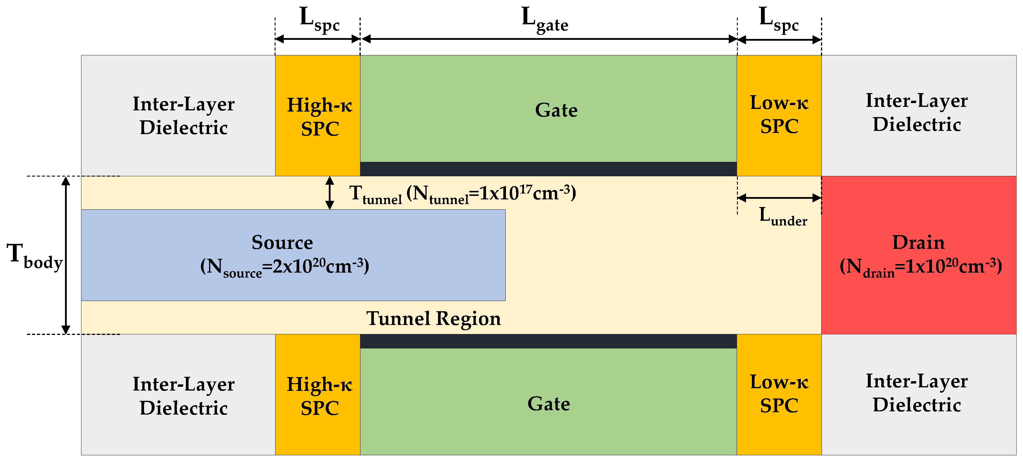
Figure 1. The schematic of the proposed tunnel field-effect transistor (FET), which have double gate, asymmetric spacers, and a tunnel channel region to improve the tunneling current.
Applsci 10 03054 g001
Figure 2. (a) Transfer characteristics at VDS = 1.0 V (b) output characteristics at VGS = 1.0 V with different κ values of spacers.
Applsci 10 03054 g002
Figure 3. (a) Two-dimensional (2D) contour mapping of electron tunneling rate at VGS = 1.0 V for the spacers with κ = 3.9 and κ = 25. (b) Averaged electron tunneling rate, and (c) averaged electric field at VDS = 1.0 V in the channel region under the spacer.
Applsci 10 03054 g003
Figure 4. Transfer characteristics with various spacer thickness (1–5 nm) based on κ = 25.
Applsci 10 03054 g004
Figure 5. (a) 2D contour mapping of electron tunneling rate at VGS = −0.3 V and VDS = 1.0 V for the spacers with κ = 3.9 and κ = 25. (b) One-dimensional (1D) energy band diagram along the channel direction and electron tunneling rate between the channel and drain.
Applsci 10 03054 g005
Figure 6. Gate-to-drain capacitance-voltage characteristics at VDS = 0.0 V with different κ values of spacer. Outer fringing gate-to-drain capacitance (Cof) can be extracted at VGS = −1.0 V based on ideal junction.
Applsci 10 03054 g006
Figure 7. (a) Gate-to-drain capacitance-voltage characteristics at VDS = 0.0 V with symmetric high-κ spacer (κ = 25) and asymmetric high/low-κ spacer (κ = 25/3.9). (b) Inverter response characteristics with symmetric low-κ spacer (blue), symmetric high-κ spacer (green), and asymmetric high/low-κ spacer (red).
Applsci 10 03054 g007
Figure 8. Process flow for the proposed tunnel FET with asymmetric spacers. (a) oxide and poly-Si deposition on SOI wafer. (b) drain-side patterning by photolithography and etching, low-κ spacer and drain region formations (c) oxide passivation on drain-side and poly-Si removal. (d) based on nitride spacer formation, oxide and partial silicon etching, then source region and channel epitaxy formation. (e) nitride and high-κ spacer formations. (f) oxide passivation on source-side and high-κ/metal gate process.
Applsci 10 03054 g008
Table 1. Structure dimensions used in technology computer-aided design (TCAD) simulation.
DefinitionParameterValue
Gate LengthLgate100 nm
Equivalent Oxide ThicknessTox1 nm
Spacer ThicknessLspc0–10 nm
Spacer Dielectric Constantκspc3.9–25
Body ThicknessTbody20 nm
Tunnel Region ThicknessTtunnel4 nm
Drain Underlap LengthLunder10 nm
Tunnel Region DopingNtunnel1 × 1017 cm−3
Source DopingNsource2 × 1020 cm−3
Drain DopingNdrain1 × 1020 cm−3