Review

Manufacturing Processes of Integral Blade Rotors for Turbomachinery, Processes and New Approaches

by
Haizea González-Barrio
1,*,
Amaia Calleja-Ochoa
2,
A. Lamikiz
3 and
L. N. López de Lacalle
3
1
Department of Mechanical Engineering, University of the Basque Country (UPV/EHU), Alameda de Urquijo s/n, 48013 Bilbao, Spain
2
Department of Mechanical Engineering, University of the Basque Country (UPV/EHU), Nieves Cano 12, 01006 Vitoria-Gasteiz, Spain
3
The Aeronautics Advanced Manufacturing Center, CFAA—University of the Basque Country (UPV/EHU), Parque Tecnológico de Zamudio 202, 48170 Bilbao, Spain
*
Author to whom correspondence should be addressed.
Appl. Sci. 2020, 10(9), 3063; https://doi.org/10.3390/app10093063
Submission received: 3 March 2020 / Revised: 20 April 2020 / Accepted: 24 April 2020 / Published: 28 April 2020

Abstract

:
Manufacturing techniques applied to turbomachinery components represent a challenge in the aeronautical sector. These components are commonly composed of high resistant super-alloys; in order to satisfy the extreme working conditions, they have to support during their useful life. Besides, in the particular case of Integrally Bladed Rotors (IBR), they usually present complex geometries that need to be roughed and finished by milling and grinding processes, respectively. Thermoresistant superalloys present many challenges in terms of machinability what leads to find new alternatives to conventional manufacturing processes. In order to face this issue, this work presents a review of the last advances for IBR manufacturing and repairing processes.

1. Introduction

The aeronautical industry is considered one of the strategic sectors of the global market. According to the Spanish Association of Defense, Aeronautics and Space Technology Companies (TEDAE), this sector generates a total revenue of 7.8 billion EUR, from which 11% is assigned to R&D&I (Research, Development and Innovation) activities [1]. For this purpose, it is necessary to work not only on the improvement of new components but also in looking for new innovative processes, alternative to conventional manufacturing processes, and optimizing cutting tools, tool-paths, machining strategies and material properties. Nevertheless, it should not be forgotten that the main objective of performing more productive and efficient processes is reducing machining times and costs along the entire manufacturing chain.
Turbomachinery rotary components in aircraft engines, mainly in the compressor and turbine stages, present a complex geometry composed of a series of bladed discs distributed along the same rotor. In some cases, these components are an assembly of smaller pieces, mounting single blades in some rotor section, which in turn is mounted on the final rotor. In the last decades, there was a new trend to integrate blades and the rotor in a monolithic component, that is, to produce the entire components from an starting disc eliminating materials by means of five-axis milling process, reaching a component with the maximum strength and minimum weight. The common definition for this kind of components is integral blade rotor IBR (Integrally Bladed Rotors), or blisk (from blade on disc). In addition, comparing IBRs with assembled discs, the component weight is reduced up to 20–30%, increasing the efficiency considerably, reducing at the same time the fuel consumption and gas emissions. Nonetheless, these components present some difficulties: elevated machining times, cutting tool costs and a surface integrity that must be kept in healthy values, all which are aspects dependent on machine kinematics [2]. With the aim of manufacturing these components and avoiding the former issues, blades are manufactured directly using conventional machining processes (i.e., milling, turning, etc.) over a revolution body, thus obtaining a compact component with more complex geometries because original assembly junctions are avoided. However, turbomachinery integral rotary component manufacturing presents some difficulties, such as accessibility and geometrical complexity, among others. Therefore, manufacturing process optimization is the principal target for large aeronautic engine manufacturers. Blade geometries are complex and present internal cooling ducts. They combine different materials and microstructures for the disc and blades with the aim of improving/optimizing mechanical properties. Figure 1 shows a HF-120 turbofan engine from GE® and the differences between IBRs and assembled discs.
The selection of machining processes for component manufacturing will depend on the component material and geometry [4]. Due to hard working conditions, there are several materials presented in aeronautic motors [5]. Additionally, with the aim of standing those extreme working conditions, materials should fulfill some extra requirements such as good resistance to impact loads, fatigue and erosion and a high ratio between mechanical resistance and material density [6]. Moreover, depending on the application, different thermal forces and pressures are present. Notable are nickel alloys for the so-called “hot” zones such as combustion chamber and turbine inlet and titanium alloys for “cold” zones such as compressor inlet and turbine outlet. These materials are known as difficult-to-cut materials, and it is necessary to analyze which is the most appropriate manufacturing process depending on the concrete material and geometry. Integral blade rotors must be made of hard-to-machine alloys (Ti-6Al-4V and Inconel®718), which represent a machining technological challenge from the economic and technological points of view.
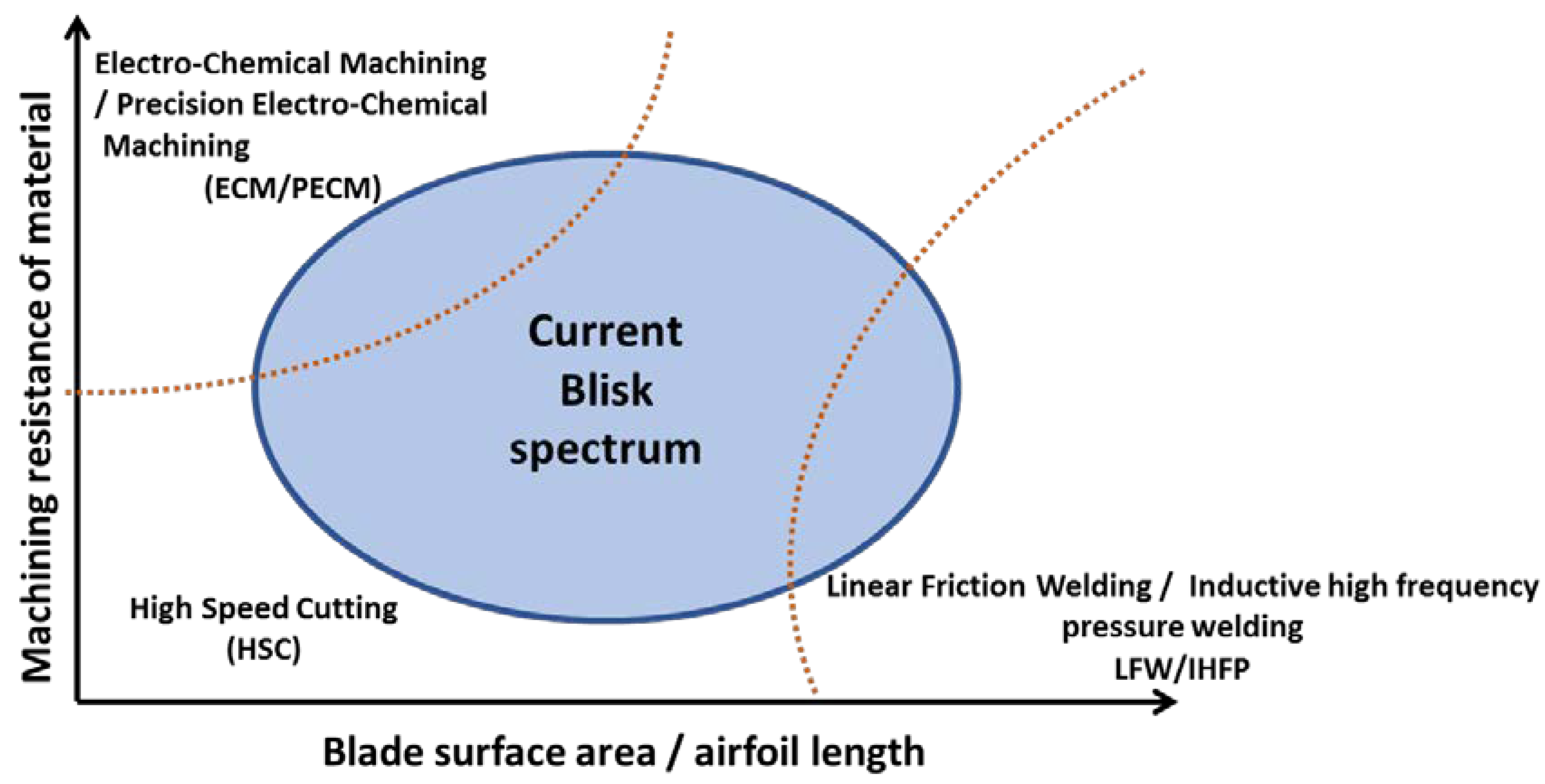
The classification of manufacturing processes is conditioned by component characteristics, sector of applications, material requirements and geometrical definition. Among IBR definition, the geometry is divided into two main groups based on the relation between the length or blade areas and the diameter of the disc. Figure 2 presents IBRs manufacturing processes in accordance with this relation, which shows the use of monolithic manufacturing processes for small-medium diameters and union processes for big diameters [7].
The first group, where the component size is elevated, involves geometries as the fan at first stages of low-pressure compressors. These components are commonly made by forging and manufactured by union processes; applying a welding process between single blades and the main disc. Among welding processes, Linear Friction Welding (LFW) and Inductive High Frequency Pressure Welding (IHFP) are found [8].
The LFW process consists in fixing strongly the disc while single blades are oscillating along a linear movement; the generated friction leads to the necessary heat to obtain a welding clad between both components. Finally, a milling process is performed to remove the remained extra material [9]. At the present time, this technique obtains welding results with high integrity, low distortions and fine grain microstructure in the thermal affected zone [10]. The IHFP process uses a high-frequency alternating current that generates an elevate electromagnetic field heating the materials up to the required temperature [2]. Inside this group, the Abrasive Water-Jet Cutting (AWJC) is presented as an alternative for blisk roughing strategies with blades length over 150 mm and cutting widths of 100 mm [11].
The second group encompasses IBRs geometries with small blades size compared with the component diameter, such as high-pressure compressor stages. Currently, these components are manufactured using High Speed Cutting (HSC) of a monolithic piece due to the process flexibility, and the wide knowledge of this conventional process. Alternative manufacturing processes include: Casting, Pulse/Precise Electro Chemical Machining (PECM), Electro Discharge Machining (EDM), Additive Manufacturing (AM), Grinding and Super Abrasive Machining (SAM).
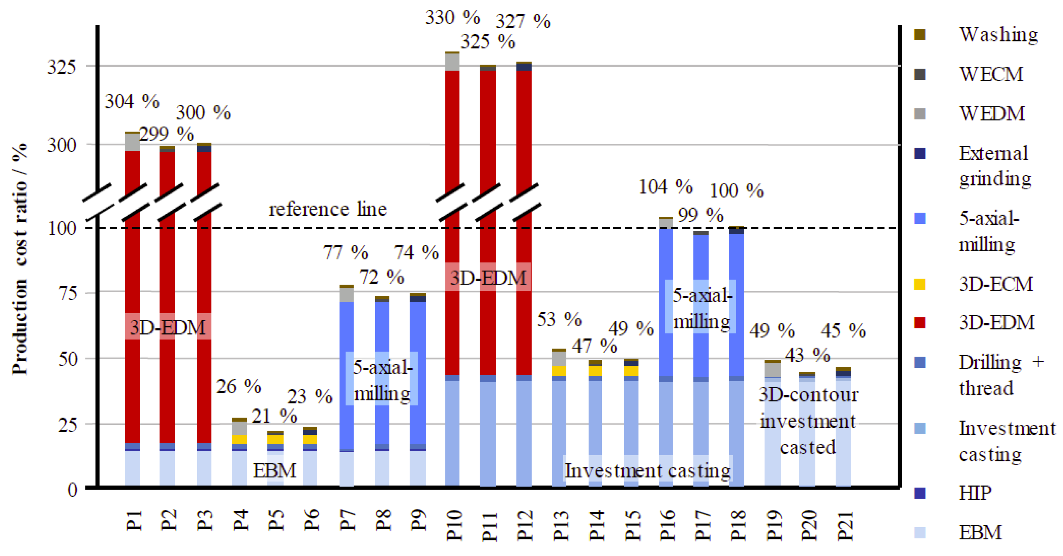
With the aim of reducing material waste and manufacturing times, near-net-shape processes are becoming an alternative as a primary process: Additive Manufacturing (AM), Casting and Sintering. Nonetheless, the high complexity of these components is still a handicap compared with the forging preforms that achieve good mechanical properties and higher resistances due to optimal metallic material fiber orientation [12,13]. One of the most popular post-treatments to optimize these primary processes is known as Hot Isostatic Pressing (HIP). The HIP consists in applying elevate temperature (482 °C for aluminum to 1320 °C for nickel-based superalloys) and pressure (range: 50.7–310 MPa, being 100 MPa the most common pressure) simultaneously on the part, removing porosity and improving mechanical properties [14]. Considering those new alternatives and their combination in order to obtain the optimal IBR manufacturing process, Klocke et al. [4] performed a technological and economic analysis determining seven different process chains combining milling, PECM, ECM and AM, establishing a complete machining process as the reference process. Following the same objective of finding the optimal IBR manufacturing process chain (Figure 3) shows a comparative chart between 20 reliable process chains, based on a previous technological analysis, defined for a Ti-based impeller manufacturing [15].

2. Monolithic Components: Manufacturing Processes

Hereafter, manufacturing processes for monolithic components (small-medium size IBRs), corresponding to Figure 2, center to left region, are described more in detail, with their main advantages, drawbacks and applications.

2.1. Casting

Sand Casting is used for medium-small impellers that do not require elevated finishing accuracy and mechanical properties. This is the case of automotive turbocharger application [16]. This type of impeller does not require tough tolerances, and it is generally manufactured in big batches. These components are widely used for automotive reciprocating internal combustion engines, particularly for diesel cycles. These engines consist of a turbine and a compressor, where the impeller is connected coaxially.
Casting impellers are used, in usual manner, for centrifugal pump impellers [17]. Impellers fabricated by sand casting are commonly made of steel, bronze, brass, aluminum or plastic. Sand casting can be used to mold high melting point components and is suitable for both small and large series sizes. However, dimensional precision and surface finish are generally limited.

2.2. Electro Discharge Machining (EDM)

The Electro Discharge Machining (EDM) is based on an electro-thermal machining process; an electric discharge is generated between an electrode and the desired part immersed in a dielectric medium, requiring both materials to be conductive. The heat generated by the discharge melts and evaporates part material and to a lesser extent the electrode. Despite of being a manufacturing process adequate to obtain complex geometries with tough tolerances, which cannot be achieved with other manufacturing processes, the main drawback lies on the reduced material removal rates. Moreover, the thermal nature of this process causes a molten metal superficial layer (with different properties than base material) that affects fatigue response [18]. Nevertheless, this technology evolved to eliminate these surface integrity issues for thermoresistant superalloys such as Ti6Al4V and Inconel®718 [19].
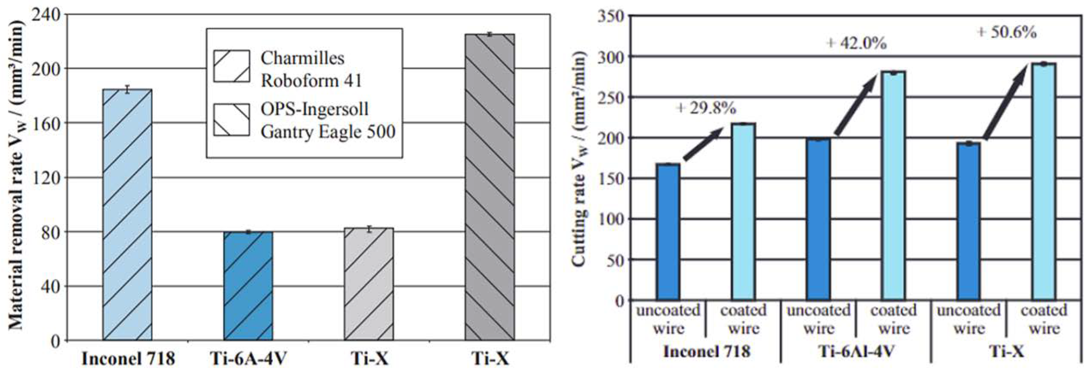
This technology is commonly used for low-machinable materials as titanium and nickel-based superalloys (Figure 4). Due to the fact that there is no direct contact between the tool and the desired part, the effect of the material does not cause cutting force and does not influence the erosion process [20]. Klocke et al. [21] performed a technological and economical comparison of roughing via milling, WEDM (wire electro discharge machining) and SEDM (sink electro discharge machining) for titanium and nickel-based blisk concluding that EDM as the most economical roughing process and a real alternative for large batches, up to 400 blisk per year.
This manufacturing process is a feasible alternative for closed-type blisk and impellers (Figure 5), known as shrouded blisk, integrated impeller and hooded impeller. This type of geometry presents tool accessibility inconveniences for the conventional milling process to be manufactured from a monolithic part. The main challenges for EDM-ing these blisk and impeller components consist in optimizing electrode design and tool-path programing for the cavity performance [22].
Furthermore, these applications require the use of a machine with more than 3-axis, which are difficult to interpolate. Additionally, various electrodes are necessary to achieve the final desired form [23]. Now, many technical studies about blisk/impeller manufacturing with cylindrical and complex form electrodes using multi-axes numerical control strategies are highlighted [24,25].

2.3. Electro Chemical Machining (ECM)/Precise Electro Chemical Machining (PECM)

The Electro Chemical Machining (ECM) is a non-conventional material removal machining process by electrolysis where a voltage is applied between a form electrode (cathode) and the part to be manufactured (anode) through an electrolytic liquid [26,27]. The removed material precipitates in the electrolytic solution as metallic hydroxide. The machining process is performed without thermal and mechanical stresses, thus material properties are not disturbed, so there is no presence of white layer. It is presented as a good alternative for big batches and very low machinable materials because the electrode presents a reduced wear, but the machine investment is high. In the classical process, a direct current voltage between 5 V and 10 V is applied, achieving feeds up to 10 mm/min. Figure 6 shows a diagram of ECM methodology and the application of this technique under different process parameters with the aim of determining optimal ECM parameters for Ti60 related to the surface roughness [28].
The Pulse/Precise Electro Chemical Machining (PECM) is a variant of ECM that combines a pulsed voltage with an oscillate movement of the cathode, obtaining a better finishing accuracy. The main inconvenience presented by this process is that the machine investment is higher and cutting feeds are lower, around 0.5 mm/min [5,29].
One of the main applications for these ECM and PECM techniques are the blisks located in the high-pressure turbines compressors. For aeronautical turbines, the material resistance and hardness are crucial to withstand the extreme working temperatures; thus, they directly impact on material machinability, leading to the necessity of difficult-to-cut thermoresistant superalloys, nickel forged parts, sintering materials, nickel-based alloys, among others.

2.4. Additive Manufacturing (AM)

Over the last three decades, Additive Manufacturing (AM) has become a competitive alternative or compliment in such a strict sectors as the aeronautical and the automotive. This technology is still in early stages; however, it presents many new opportunities in terms of material waste and sustainability. By the end of the 80s, the first generation of Material jetting (MJ) commercial 3D system rapid prototyping machine was developed. During the early 90s, the MIT (Massachusetts Institute of Technology) developed the first Binder Jetting (BJ) method with a powder bed similar to the actual Powder Bed Fusion (PBF) processes [30].
At the beginning, this technology was utilized for prototyping and small fixtures, but step by step, it has been expanding and replacing other manufacturing processes for small batches. Among different AM processes, processes most commonly used for entire part creation consist in placing a flat powder layer of the part material, which is then heated and solidified using electron beam (Electron Beam Melting or EBM) or laser [31]. Thus, the final desired form is generated by overlapping of single layers.
The main challenges for these technologies reside on good heat dissipation generated during the process and reducing distortions. On the contrary, these technologies offer advantages as the good powder utilization reducing material waste and the possibility of generating complex geometries, which are impossible to other technologies. They achieved tolerances for Ti and Ni based superalloys with material components using AM in the order of 100 µm or higher. It should be pointed that, in the case of using AM for Ti alloys, it is necessary to consider this material tendency to oxidation; that is why EBM technology is preferred, helped by an inert gas [32,33]. Overall, the process does not have the capability of achieving the tough finishing dimensional requirements, a finishing stage being needed with a material removing manufacturing process [34].
In 2015, Boeing Company filed a patent application for defining airplane components that are going to be produced by AM, covering 300 part numbers on 10 different aircrafts [35]. Airbus is also promoting AM components in their aircrafts; on 30 March 2017, the first fully 3D printed hydraulic spoiler manifold flew in an A380 [36].
Another AM technology that is an outstanding process in the aeronautical sector is the Direct energy deposition (DED). In this technology, a laser is in charge of melting the substrate meanwhile a nozzle injects the metallic powder to be added in the area of the melting pool. During the process, it is protected by inert gas streams to avoid interactions between melted materials and the oxygen [37]. Creating consecutive clads, a layer or coating is generated and, consequently, when overlapping layer over layer, it results into the 3D final desired geometry.
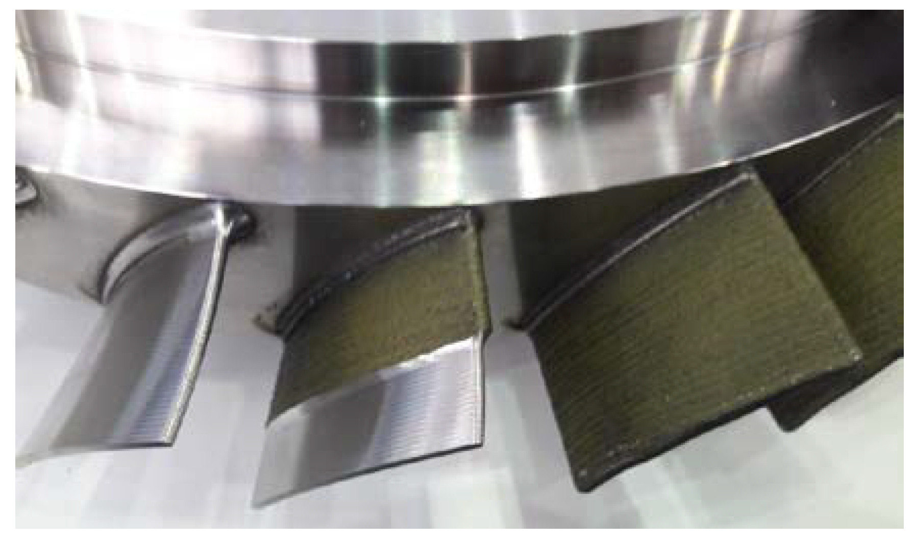
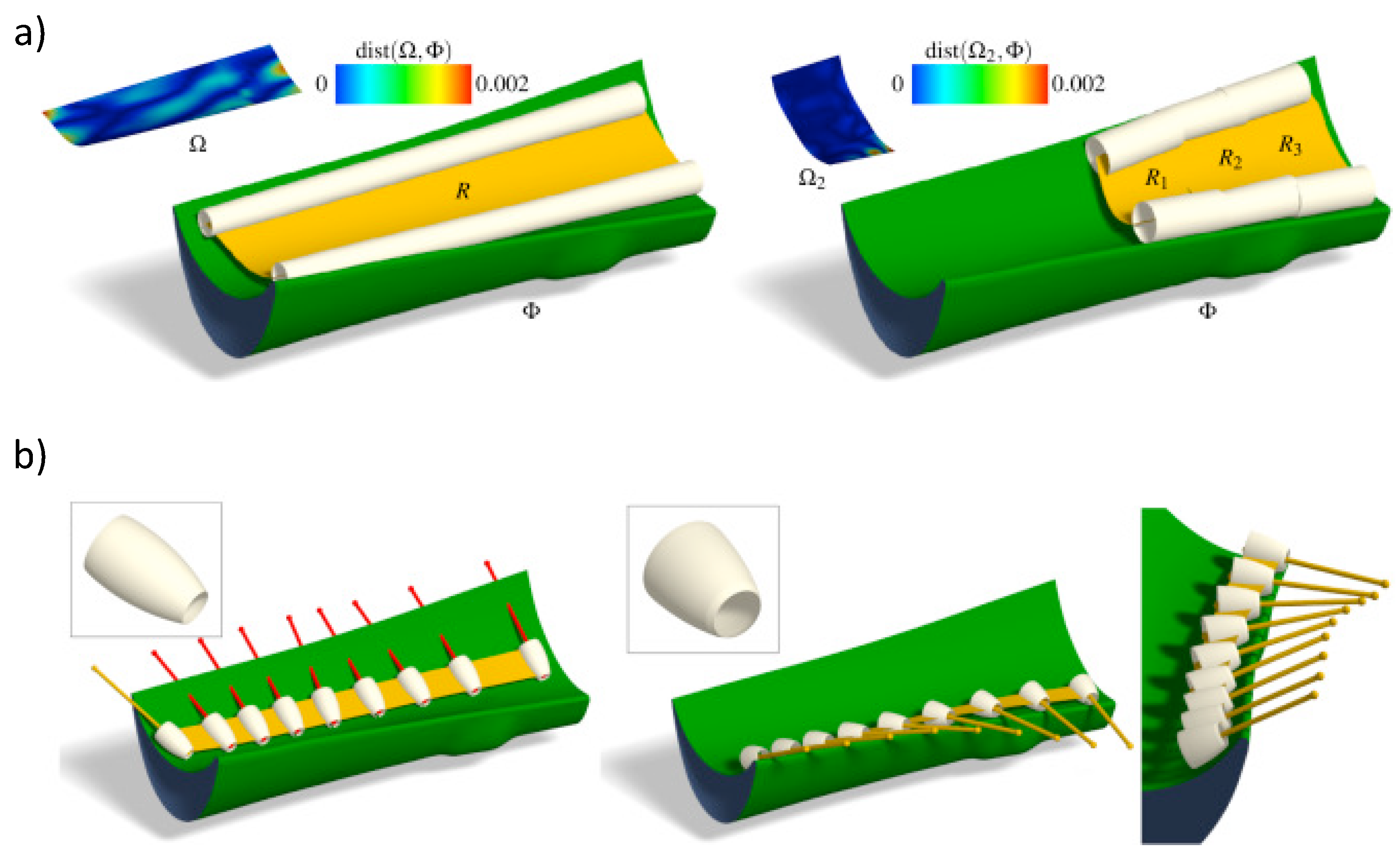
The LMD main applications are direct blades fabrication for small blisks and for damaged area repairing process (Figure 7). For repairing operations, LMD process requires previous stages: component damaged area inspection, repairing tool-path strategy definition, studying repairing necessities and feasibility and, finally, a measuring and control stage for the final obtained geometry and the material properties [38]. In both, direct blade manufacturing and damaged component repair through LMD [39], a posterior stage of machining is required to achieve the final desired geometry accomplishing tolerance requirements. Hence, this additive manufacturing process provides an initial geometry closer to the final geometry, so it is addressed inside the “Near-Net-Shape” concept [40].

2.5. Conventional Machining Process: 5-Axis Milling

The conventional milling process consists in a rotary cutting tool that removes material from the workpiece surface until achieving final desired geometry [41]. It was in 1795 when Eli Terry used the first milling machine for the clock industry [42], but it was not until around 1810 when the milling concept was considered independent from turning technology [43]. This process suffered a drastic evolution thanks to Computers and CNC improvements in the 80′s [44]. Nowadays, the milling process embraces numerous capabilities for complex geometry generation and multiple materials, offering flexible solutions.
Related to IBRs manufacturing processes, for medium-sized impeller and blisk manufacturing, 5-axis milling is the conventional material removal process most commonly used. Thus, a complete component is machined from a solid block, obtaining a monolithic piece without discontinuities between the different elements, so junctions are avoided, obtaining superior mechanical properties. These advantages are critical for turbomachinery rotary components because they are exposed to elevated temperatures from exhaust gases (900–1400 °C) and extreme working conditions, so heat resistant superalloys are required such as Inconel®718 or Inconel®615. Comparing blisks with assembled discs, the weight is reduced up to 20%, increasing the efficiency considerably, reducing at the same time the fuel consumption and gas emissions. Nonetheless, this process presents some difficulties: elevated machining times, tool costs and a surface integrity dependent on machine kinematics.
As it was mentioned previously, Ti and Ni alloys are the materials used for these types of components, and they are characterized by their low machinability, so Figure 8 shows the expected material removal rates and cutting conditions ranges recommended for these materials and components [4,21].
Even though the principal impeller application manufactured by this process is the aeronautical engine, there are many applications not as popular that should be highlighted: high-speed watercrafts and motorboats, washing machines, vacuum cleaners, water propellers and ventricular assist devices.
In the case of medium-sized blisks, milling is the most usual manufacturing process, especially for titanium alloys and Inconel®718. These components are commonly placed in the medium- and high-pressure turbine compressors for aeronautical engines. Being located in the compression areas, both the high- and the low-pressure zones from the engines, materials need to present good resistance properties to high temperature and pressure; therefore, they are made of difficult-to-cut materials, such as forged materials, cast blades, monocrystalline materials, etc. At this time, new challenges are presented related to materials because the traditional Ti6Al4V tends to be replaced by Ti6242 and Ti6246 alloys, as well as the Inconel®718 by the DA718.

2.5.1. Cutting Tools and Tool Holders

One of the main advantages of the conventional milling process is the great adaptability for a huge variety of geometries and range of tool size and form that could be found in the market for many different applications. Usually, solid coated carbide mills are the tool types recommended for blisk and impeller manufacturing processes. Solid carbide mills are standardized in a range of diameters from 2–16 mm; moreover, carbide tools present good tenacity and heat resistance for machining Ti and Ni superalloys [45]. Besides that, indexable milling cutters are an economical alternative for some specific operations, concretely roughing operations, though their use is not very extended for these components manufacturing. Furthermore, coatings (TiAlN, TiN, AlCrN, AlCr and CrN) add real advantages to these cutting tools improving the resistance to friction, temperature, oxidation and corrosion. Finally, General Electric patented an alternative for roughing curved slots using indexable milling cutters instead of solid carbide tools [46].
From the tool forms point of view, frontal, frontal with corner radius and spherical are the most popular for IBRs manufacturing (Figure 9). Frontal mill is indicated for roughing because the cutting speed depends on the tool diameter, so in this case, it does not decrease at the tool tip. Frontal tools with corner radius are one alternative to be used in order to avoid the excessive wear suffered by cutting edges in 5-axis milling movements. Moreover, these corner radiuses are also adaptable to the blades blend, making them an option for semifinishing operations. Conical tools are normally selected for semifinishing and finishing operations; more specifically, they access the entire cutting length in those cases when the surfaces are ruled. Spherical tools are used for finishing strategies. Moreover, in some cases that present concave surfaces with small curvature radius, spherical tools are the only feasible solution. Finally, there is a new trend to barrel shaped tools; some studies around this form led to the conclusion that they are a real alternative for semifinishing and finishing non-extremely curved blades [47]. The main advantage of this cutting tool form resides in the curvature radius that allows reducing the number of passes, and the machining time [48].
In addition to the foregoing, the adequate choice of the tool holder also influences the milling process. On the one hand, each holder type presents different characteristics in terms of accuracy, clamping forces or lubricooling systems. On the other hand, milling strategies closer to blade blends require a holder with smaller body to avoid collisions. Hence, thermal tool holders fit with these requirements.
IBRs and blisk manufacturing will be reducing time meanwhile new cutting tools experimentation would be performed. Superalloy machining is a hot topic today, both in performance aspects [48,49] and in the effect on final residual stress and surface integrity [50]. Sintered carbide tools are in rapid evolution, along with coatings [49,51,52]. However, the introduction of Gamma TiAl in this business [53] is not expected, due to extreme fragility of the aluminides, which only can be produced with enough reliability with ECM.

2.5.2. Manufacturing Strategies

Manufacturing processes for complex geometries are still for many researchers a subject matter related to the number of aspects involved. In the first instance, it should be outlined that the programming of these complex geometry machining strategies is commonly performed by CAM software, since manual programming is practically impossible. Nevertheless, roughing and semifinishing strategies, before the finishing stages, require special attention because it is at those stages the machining process productivity can be optimized [54,55].
IBRs manufacturing processes optimization is focused on prioritizing the productivity for roughing strategies and accuracy for semifinishing and finishing strategies. Productivity mainly depends on the machining times and tool cost. Despite the great technological advances related to milling cutting tools, the IBRs manufacturing still requires the use of a lot of milling tools due to the tool wear and breakage. In addition, the increase of productivity with aggressive cutting conditions and strategies implies the rise of tool wear. Therefore, the main objective for roughing stage is achieving a balance between productivity and process costs.
Figure 10 shows three of the most applied roughing strategies: slotting, trochoidal milling and plunge milling. Full slotting strategy consists in using the complete diameter as the radial depth of cut (ae). The main advantages of this strategy are the high material removal rates in steady state and the simplicity of the required tool-path. Nevertheless, this strategy causes elevated radial cutting forces, so in some cases, the axial cutting depth needs to be performed in many passes. Trochoidal milling combines the tool linear movement with circular trajectories, implying less tool wear compared with slotting [56]. Moreover, radial cutting forces are smaller, which offers the option of using higher cutting speed and axial depth of cut. The main drawback of trochoidal milling is that it requires higher machine dynamic capabilities to perform the continuous circular movements [57]. At the plunge milling, the tool moves along the tool axis (z-axis); the machining is performed with the secondary edge, and lateral vibrations are avoided. Some plunge applications are cited hereafter: deep slots, insufficient stability and materials with low machinability [58].
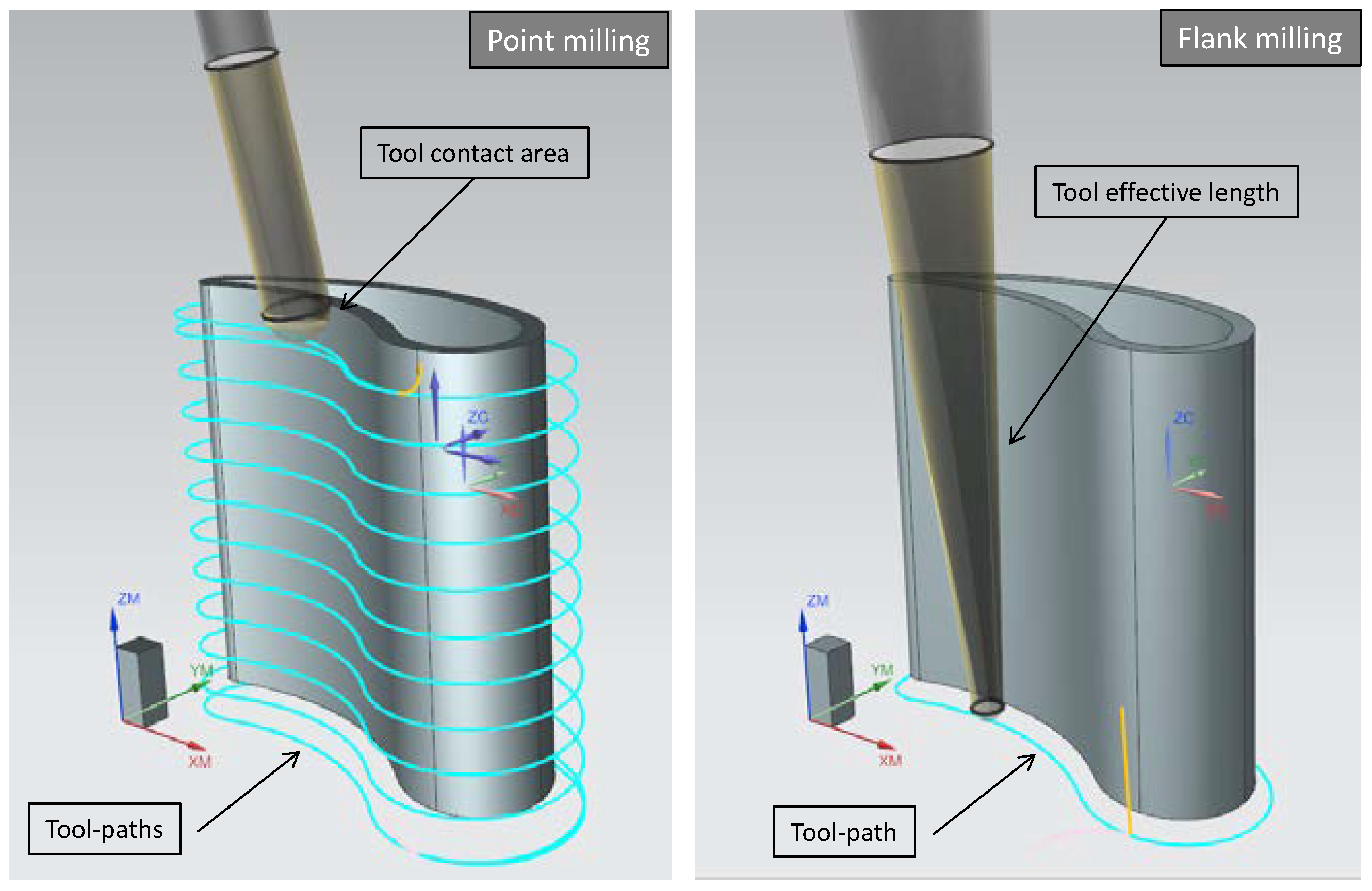
On the other hand, semifinishing and finishing strategies define final geometry, dimensional tolerances and surface finishing requirements. Milling strategies are categorized as a function of the tool contact surface during the machining, differing two types for complex geometries: point milling and flank milling (Figure 11). The point milling strategy is performed with ball-nose cutting tools, and the material removal is conducted with the spherical side of the milling tool. This strategy’s main drawback resides on its high machining time and the extreme tool wear because it is constantly cutting with the same tool region. On the contrary, at flank milling strategy, the machining is performed with the total effective length of the tool, so the productivity of this strategy is higher than the point milling, reducing machining times and making the maximum use of tool cutting edges. Nonetheless, this is not always a useful option for complex geometries because the accuracy of this strategy depends on the surface type being necessarily a developable ruled surface for its adequate application. Moreover, another inconvenience of this strategy is found in the operation stability, since it is much influenced by the defined cutting parameters; if they are not the appropriate ones, there is a possibility of vibrations appearing; leading to inadmissible finishing requirements. On top of that, for difficult-to-cut materials, it should be pointed out that the bigger the contact between tool and part is, the higher power, stability, chip evacuation and machine capabilities are required.
In those cases that the geometries to be machined are developable ruled surfaces, the tool flank is maintained tangent to the surface along the entire tool axis. A ruled surface is a curved surface that can be generated by continuous motion of a straight line in space along a space curve called a directrix. Moreover, a developable surface is a special ruled surface that has the same tangent plane at all points along a generator. Therefore, flank milling strategies keep that tangential contact between the tool axis and the surface along each generatrix that defines the surface, permitting the use of the total effective tool length as the axial depth of cut (ap). This leads to a more productive process, with higher material removal rates and a machine time and cost reduction. Nevertheless, to ensure process stability and efficiency, the use of tools with big dimensions is required, reducing bending risks and vibration appearance inherent to this strategy.
It is important to emphasize the differences between developable and non-developable ruled surfaces. A non-developable ruled surface is a ruled surface that does not have the same tangent plane at all points along a generator. The use of flank milling for non-developable surfaces implies an error studied by Senatore et al. [59]. The error expression was reduced analytically to an expression that relates the radius of the tool and the angle between the tangent planes at both extremes of the surface isoparametrics. Additionally, Senatore et al. [59], considered three special cases: (1) the radius of curvature Oi is larger than the tool radius, (2) when the twist angle (αi) is small and (3) a combination of both, Oi larger than the tool radius and a small twist angle, this last case being the one that fits with the ruled surfaces used for turbine blades. Figure 12 shows the tool cut into cross sections and the principle for error estimation.
When ruled surfaces are also developable surfaces, both tangent planes to the isoparametric line are coincident, leading to a null error. It is noteworthy that there are numerous research works about flank milling optimization algorithms. Some of them are based on a surface approximation to the tool envelope and tool axis position optimization for each point in the surface to be machined.

2.6. Super Abrasive Machining (SAM)

Abrasive processes need to be considered as a possible alternative for IBRs manufacturing. There are some non-conventional abrasive technologies (abrasive flow machining, magnetic abrasive finishing or magneto-rheological abrasive flow finishing) characterized by their good performance for complex geometrical cavities with limited accessibility for conventional processes, achieving great dimensional accuracies and finishing surface quality requirements [60]. However, at the same time, these processes present low material removal rates, implying less productivity in terms of machining time and costs [61].
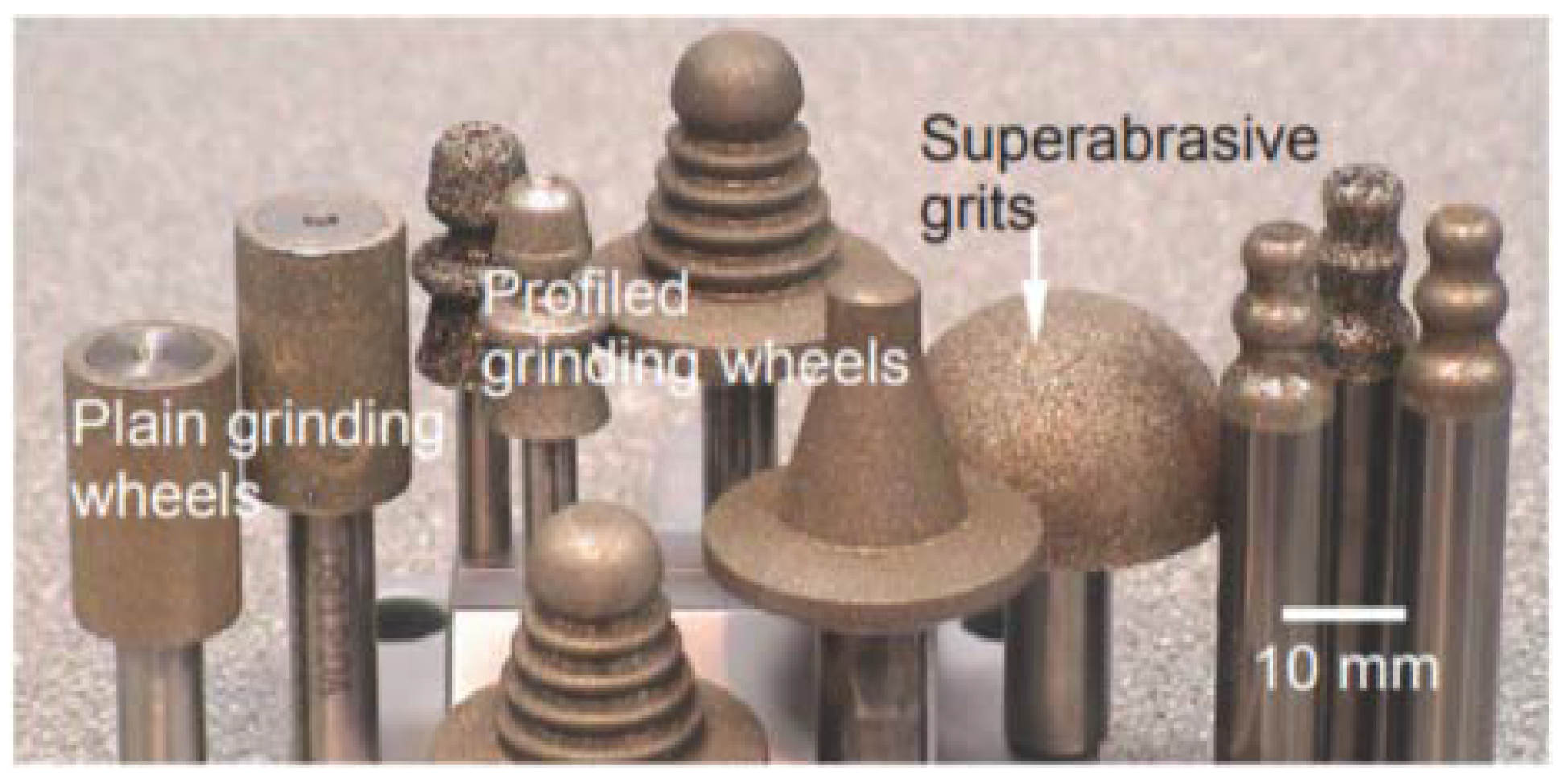
In the last decade, a new abrasive process was developed, known as Super Abrasive Machining (SAM), on the path of finding innovative technologies to cover these productivity issues. R. Petrilli [62] defined this process as “grinding at machining rates”. Therefore, this technology provides, under similar cutting conditions of single point machining, a finishing precision closer to grinding technology, which makes this process more versatile than grinding or milling techniques. The main difference between the conventional grinding and SAM is that grinding is commonly used for low material removal rates oriented to achieving final size and finishing requirements; in contrast, SAM is more adaptive for a variety and complex geometries and higher material removal rates, offering as well, elevated accuracy and surface quality. A notable difference between both processes resides on the type of abrasive tools used; SAM abrasive tools (Figure 13) cover a wide range of small geometries—diameters ≤ 25mm—and they consist on single layer electroplated superabrasive grinding wheels. Nonetheless, it also needs to be stressed that rotational speeds required to obtain the adequate peripheral cutting speeds are very high, in most of the cases over 50,000 rpms [19]. Additionally, it is noteworthy that using these kinds of tools, due to process temperature and extreme cutting conditions, cutting fluids are required, particularly cutting oil [63,64]. Regarding accessibility, SAM process presents accessibility problems in closed geometries as it happens with milling processes because the tools sizes are similar to milling ones.
The grinding technique considered as the closest rival to SAM is creep feed grinding (CFG), characterized by large cutting depths (ap = 0.1–30 mm) and high cutting speeds (vc = 20–30 m/s). Creep-feed grinding is generally a surface grinding technique employed for heavy stock removal of difficult-to-machine materials, particularly where very precise and accurate form is required on the finished surface of the workpiece [65]. Comparing both techniques, SAM achieves the equivalent amount of material removed at higher speeds, with lower workpiece loads, and more accurate dimensional tolerances (Włodzimierz Wilk, 2008). These advantages make SAM a suitable and efficient alternative to manufacture IBRs nickel-based superalloys [66].
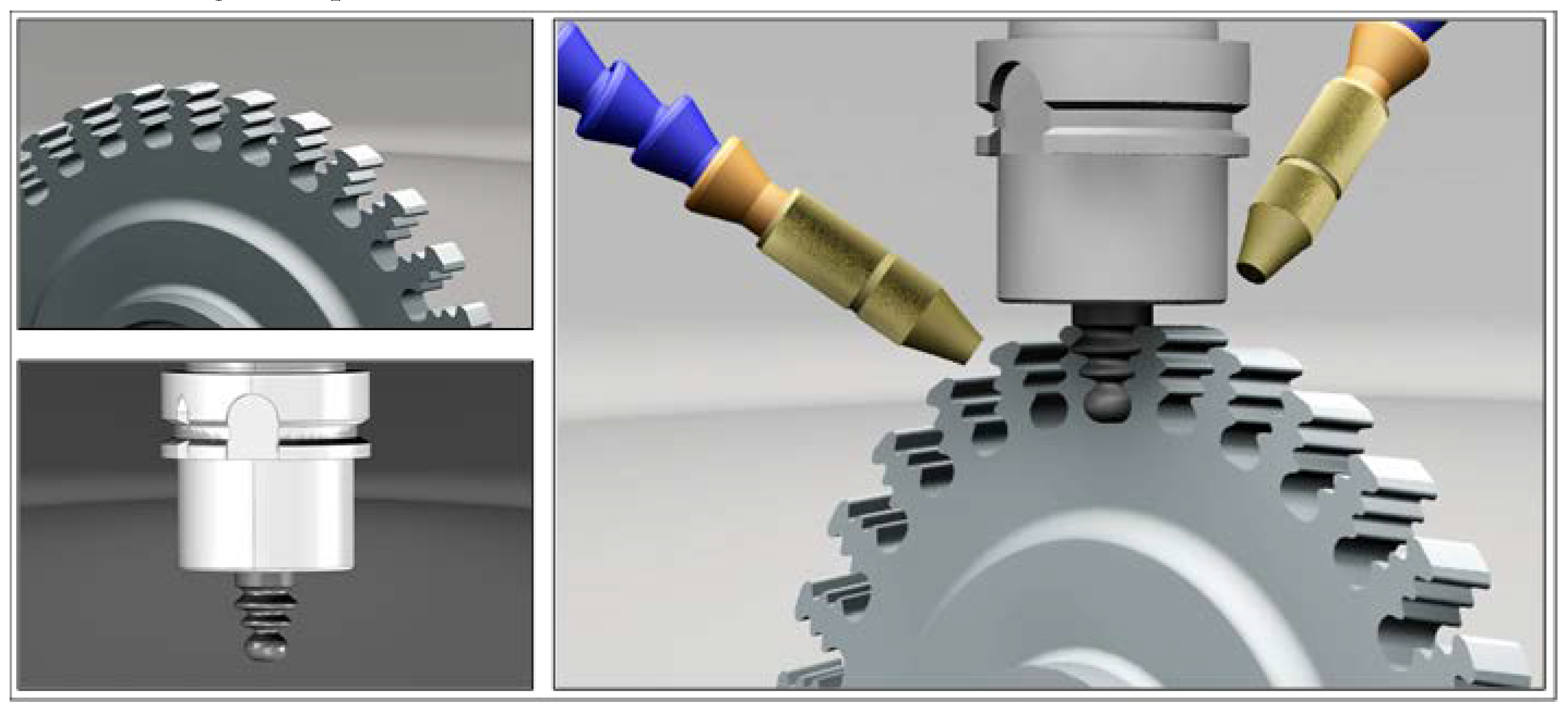
The use of SAM is recommended for three main application groups: (1) there are some manufacturing processes divided into different stages of machining, grinding and heat treatments, so in these cases, SAM could reduce all stages into only one. (2) The use on components from other near net shape processes. (3) Formed slots and flat surfaces finishing operations. Figure 14 shows some of the initial target for SAM application: fir-trees that are the junction area between the disc and single blades. Traditionally, these components are manufactured by broaching; however, this process is considered not cost effective and a time consuming. Therefore, [19] performed a set of experiments with single layer electroplated CBN (Cubic boron nitride) and diamonds wheels to manufacture fir tree roots using SAM process.
For the same application field, Curtis et al. [68] performed electrochemical SAM experiments on finishing fir trees analyzing roughness and overcut, observing low forces (37 N) with an average depth of cut of 0.92 mm.
Furthermore, SAM was presented in [69] as a solution to increase machining efficiency during the production of blades and turbine discs. It was tested with the blades from IBRs or impellers. In fact, Rolls-Royce [70] claims that under the correct performance, the process is capable of stock removal at a rate of 80 cubic millimeters per second per millimeter of wheel width. That is, eight times the achievable rate using plated CBN (Cubic boron nitride) wheel technology for super abrasive machining of nickel alloys on a conventional grinding machine. Following this researching line, H. González et al. presented a comparison between SAM and conventional milling applied to blisk geometry made of Inconel®718, performing roughing and finishing operations comparing cutting forces, surface roughness and dimensional deviation [67]. Additionally, slotting using SAM was performed and compared to conventional milling in terms of surface roughness, analyzing the cross-section and the appearance of white layer, residual stresses and microhardness, observing better results for SAM process under similar cutting conditions [71].
In a similar manner to the tendency of flank milling, flank SAM is also considered as a more productive and effective process. Hence, Wu presented in [72] a solution for obtaining Pratt and Whitney non-developable blisk geometry through flank SAM. As it was mentioned before, non-developable surfaces are not suitable for flank techniques, so this author proposed a surface modification, preserving aerodynamics and structural properties, and supplementing the manufacturing process with new tool-paths and shaped cutting tools. The results present a successful process in which the combination of flank SAM technology with the shaped cutting tools opens the possibility of new surface designs more efficient aerodynamically. For that purpose, the developed method follows these steps: (1) redesigning blade surface for improving the performance; (2) adapting the designed surface to make feasible flank SAM technique, iterating mechanical, aerodynamic and structural simulations; and finally, (3) blade manufacturing using two CBN electroplated abrasive tools, one for suction surface and another one for pressure surface.
Table 1 shows a summary of the most significant patents related to super abrasive tools and main applications, frequently developed by the main turbine manufacturer as Pratt and W→hitney, General electric and United Technologies Corporation (UTC), among others.

2.7. Algorithms to Optimise Manufacturing Processes

The generation of 5-axis simultaneous tool-paths for manufacturing free form surfaces has been a growing field of research in recent years and covers multiple areas derived from the large number of factors involved in manufacturing processes. In particular, many algorithms are developed with the aim of improving machining strategies and obtaining a more productive process. These algorithms are programmed around three main crucial aspects: tool-paths generation, optimal tool position and the avoidance of collisions [80]. Nevertheless, the three aspects are correlated between them, thus the global solution to optimal strategies programming is divided in turn into the following stages: (1) Tool definition or selection, (2) tool-path pattern and direction definition, (3) surface contact points specification, and finally, (4) local and global collisions free verification to obtain tool axis orientation. The provided solution must meet the requirements of being free of collisions, fulfilling defined tolerances and minimizing machining time. Moreover, developed algorithms need to be efficient in terms of computational costs, memory usage and be adaptive to a spread range of surfaces.
Related to IBRs, there is a common issue presented during the machining of warped surfaces consisted on the appearance of machining marks because of the sudden movements between free collision positions. With the aim of facing this issue, Chen et al. [81] proposed a solution smoothing the tool-paths performed by a ball end mills, modifying and adapting rotational positions inside the collisions free zone. In line with this solution and oriented to blisk geometries, Tung et Tso [82] used boundary surfaces to prevent extreme tool orientation changes between two points.
The traditional tool-path generation methods are iso-parametric, iso-planar and iso-scallop. The iso-parametric consists of generating the tool-paths while maintaining constant the parameter of the parametric surface [83]. The iso-planar, instead, generates the tool-paths dividing the surfaces into parallels planes in the Cartesian space, constraining it by the finishing required scallop. However, the defined constrain could offer a conservative solution not very productive and with excessive surface quality [84]. Finally, the iso-scallop method is based on keeping the scallop height constant along the entire surface, optimizing the successive stages from an initial pattern [85]. Shokrollahi and Shojaei [86] performed an experimental comparison between the three different methods machining a sculptured surface, concretely a double curvature surface, concluding that for this type of surfaces, the optimal method is the iso-scallop in terms of finishing tolerances and balanced with machining time.
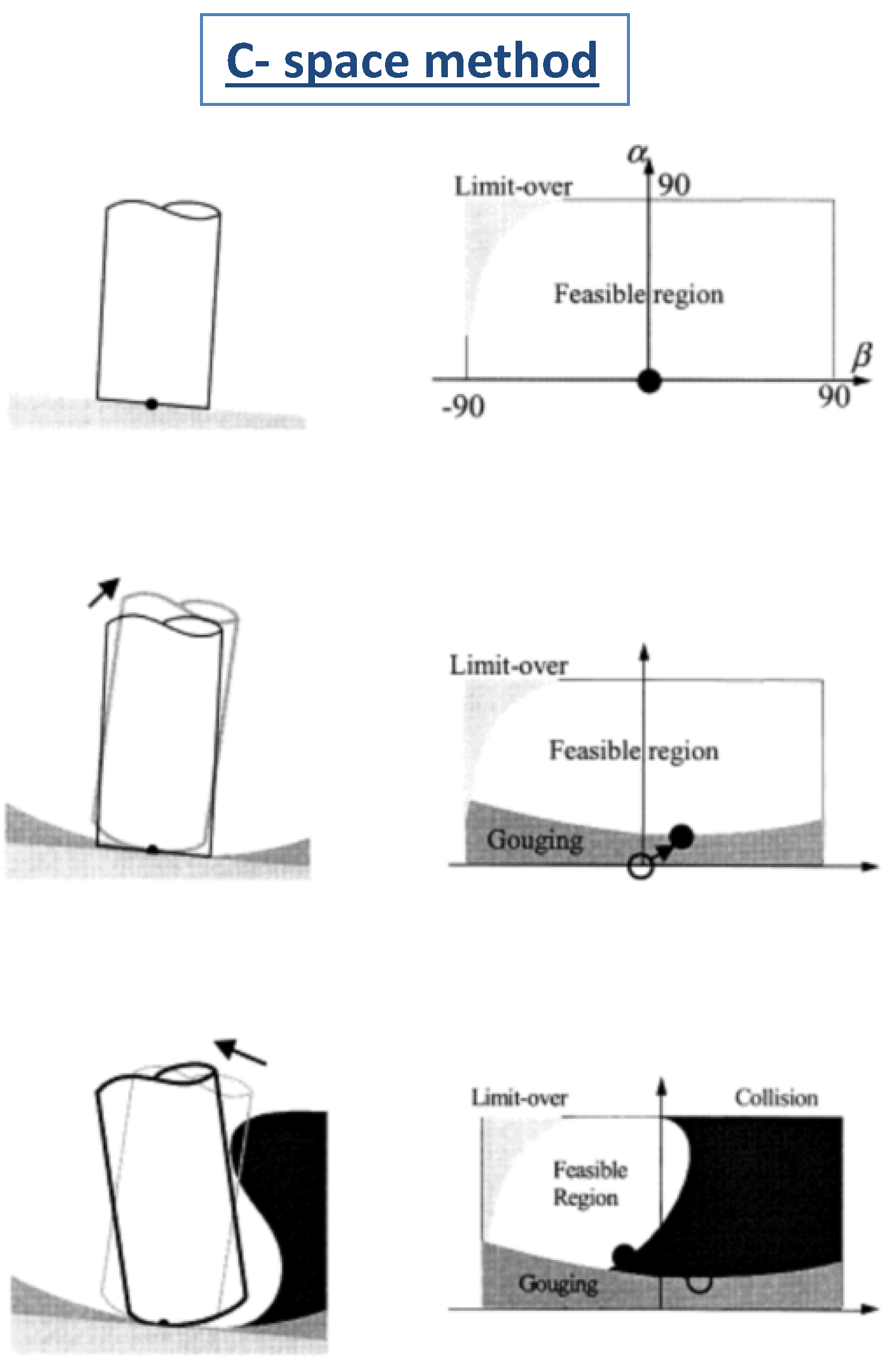
Among the most recent developments in tool-paths definition methods is the C-space (Configuration space methods) presented by Choi et al. [87] and Morishige et al. [88]. This method analyses possible configuration for a solid/rigid component with determined levels of freedom and represented as points in a C- space. These points depend on the levels of freedom and the obstacles position. Thus, it offers the chance to know which combinations are free of collisions. Figure 15 shows the C-space method applied and the analysis of the feasible regions to be machined [89]. Another technique for tool orientation definition avoiding local collisions is known as Rolling Ball Method (RBM) [90]. This method calculates different tool-paths by adjusting the contact point in curve sections, avoiding local collisions.
By following the same objective and related to roughing strategies for non-ruled complex geometries, Fan et al. [91] developed a solution calculating a ruled surface around the original non-ruled surface, simplifying calculus and tool-paths. Heo et al. [92] proposed a methodology dividing impeller roughing into 3 + 2 axes operations, calculating collision-free regions for tool-paths. Qi et al. [93] also analyzed the possibility of roughing strategy optimization for these types of components using an algorithm that calculated the optimal tool diameter. Additionally, for 5-axis machining, the process is composed of two surfaces, the guiding surface and the orientation surface; the guiding surface is the one that ensures the geometrical compliance, and the orientation surface provides the tool orientation [94].
As it was mentioned previously, flank strategies present the most productive solution in terms of machining times and costs; that is why in recent years many studies were developed to reduce the tool positioning error relative to the generatrix of the non-developable ruled surfaces. Tool repositioning methods are mainly divided into two different types, analytics and numerical; the first ones are easier to be implemented, but obtained errors are bigger than numerical ones [95]. Some of these published works focused on obtaining a surface to be machined using flank milling strategies, preserving aerodynamic properties and structural integrity near to the original surface [96,97]; other ones developed flank milling multistage techniques or tool geometry customization according to the surface [98].
Bo et al. [99] presented an algorithm that contemplated all defined stages, the approximation using envelopes to the free-form surface, a method that offers the optimal tool geometry and tool axis position (Figure 16b) and the differences presented in terms of accuracy for single patch or multipatches (Figure 16a). These types of algorithms allow to achieve a balance between optimal tool shape and position combined with the most productive tool-path. Following this line, Bo and Barton [100,101] presented an initialization algorithm for initial 5-axis milling paths of general tools easily found in standard tools manufacturers.

3. Summary and Conclusions

The ongoing evolution of the aeronautical sector and, more specifically, the monolithic components or integral blade rotors (IBRs) of the aircraft engine implies the need for new or alternative manufacturing processes offering a more productive solution in terms of costs and time.
The manufacturing and repairing processes of these complex components imply a high number of scientific-technological challenges described hereafter:
-
Complex design requirements and geometries: IBRs are classified as sculpted or free-form surfaces. For these geometries’ generation, different methods as B-Splines or NURBS are used. Therefore, additionally to the complexity of these geometries manufacturing, in some cases the accessibility for the tool along with the tough dimensional requirements are a handicap for manufacturers.
-
Difficult-to-cut materials: Present machining difficulties due to elevated cutting forces, high temperatures, limited cutting conditions and excessive tool wear.
-
High-cost production processes: Inside the IBRs manufacturing chain, many stages are presented such as, roughing, intermediate semifinishing, finishing and abrasive final operations in order to achieve desired tolerances. These stages imply higher machining times and tool wear.
This work presents a literature review describing different manufacturing processes, conventional and non-conventional processes such as Casting, EDM, SEDM, ECM/PECM, additive manufacturing, conventional 5-axis milling process and super abrasive machining, with special emphasis on the last two processes, milling and SAM, due to the fact that 5-axis conventional milling process is the most commonly used for these type of components. Finally, the evolution of mathematical algorithms for machining tool-paths optimization is discussed.

Author Contributions

Conceptualization, H.G.-B.; writing—original draft preparation, A.C.-O.; writing—review and editing, A.L.; L.N.L.d.L. paper structural coherence and integration of super alloys machining concepts. All authors have read and agree to the published version of the manuscript.

Funding

This research received no external funding.

Acknowledgments

We are grateful to Basque Excellence university Groups IT IT1337-19, and Ministry of economy project IBRELIABLE (DPI2016-74845-R), and Elkartek PROCODA KK 2019-004.

Conflicts of Interest

The authors declare no conflicts of interest. The funders had no role in the design of the study; in the collection, analyses, or interpretation of data; in the writing of the manuscript; or in the decision to publish the results.

References

  1. Asociación Española de Empresas Tecnológicas de Defensa, Aeronáutica y Espacio (tedae). Retos del Sector Aeronáutico en España, Guía Estratégica 2015–2025. Available online: https://www.tedae.org/uploads/files/1461082425_retos-del-sector-aeronautico-en-espana-guia-estrategica-2015-2025-pdf.pdf (accessed on 1 February 2020).
  2. Bussmann, M.; Bayer, E. Blisk Production of the Future Technological and logistical aspects of future-oriented construction and manufacturing processes of integrally bladed rotors. In Proceedings of the 19th International Symposium on Airbreathing Engines, Montreal, QC, Canada, 7–11 September 2009; pp. 568–577. [Google Scholar]
  3. Artetxe, E.; González, H.; Calleja, A.; Fernández-Valdivielso, A.; Polvorosa, R.; Lamikiz, A.; López de Lacalle, L.N. Optimised methodology for aircraft engine IBRs five-axis machining process. Int. J. Mechatron. Manuf. Syst. 2016, 9, 385–401. [Google Scholar] [CrossRef]
  4. Klocke, F.; Schmitt, R.; Zeiss, M.; Heidemanns, L.; Kerkhoff, J.; Heinen, D.; Klink, A. Technological and Economical Assessment of Alternative Process Chains for Blisk Manufacture. [ed.] Procedia CIRP. In Proceedings of the 15th Machining Innovations Conference for Aerospace Industry, Hannover, Germany, 18–19 November 2015; pp. 67–72. [Google Scholar]
  5. Klocke, F.; Klink, A.; Veselovac, D.; Aspinwall, D.K.; Soo, S.L.; Schmidt, M.; Schilp, J.; Levy, G.; Kruth, J. Turbomachinery component manufacture by application of electrochemical, electro-physical and photonic processes. Cirp Ann. Manuf. Technol. 2014, 63, 703–726. [Google Scholar] [CrossRef]
  6. Rao, N. Materials for Gas Turbines-An Overview. In Advances in Gas Turbine Technology; In Tech: London, UK, 2011. [Google Scholar]
  7. Bußmann, M.; Kraus, J.; Bayer, E. An Integrated Cost-Effective Approach to Blisk Manufacturing. In Proceedings of the 17th Symposium on Air Breathing Engines, ISABE, Munich, Germany, 4–9 September 2005. [Google Scholar]
  8. Bußmann, M.; Bayer, E. Market-Oriented Blisk Manufacturing-A Challenge for Production Engineering. In Proceedings of the 1st European Air and Space Conference (CEAS 2007), Berlin, Germany, 10–13 September 2007. [Google Scholar]
  9. Kumar, B.R. A Review on Blisk Technology. Int. J. Innov. Res. Sci. 2013, 2–5, 1353–1358. [Google Scholar]
  10. Mateo, A. Blisk Fabrication by Linear Friction Welding; Advances in Gas Turbine Technology: London, UK, 2011. [Google Scholar]
  11. Snecma. Method for Producing a One-Piece Bladed Disc by Abrasive Water-Jet Cutting. Patent No. EP2257409B1, 8 October 2009. [Google Scholar]
  12. Leyens, C.; Hausmann, J.; Kumpfert, J. Continuous Fiber Reinforced Titanium Matrix Composites: Fabrication, Properties and Applications; WILEY-VCH Verlag GmbH & Co.: Hoboken, NJ, USA, 2003. [Google Scholar]
  13. Bhattacharjee, A.; Saha, B.; Williams, J.C. Titanium Alloys: Part 2-Alloy Development, Properties and Applications. In Aerospace Materials and Material Technologies; Springer: Berlin/Heidelberg, Germany, 2017. [Google Scholar]
  14. de Monicault, J.M.; Guédou, J.G.; Soniak, F. Issues and Progresses in Manufacturing of Aero Titanium Parts. Safran Group, 24th ITA; TITANIUM Conference Proceedings; The International Titanium Association (ITA): Washington, DC, USA, 2008. [Google Scholar]
  15. Klink, A.; Hlavac, M.; Herrig, T.; Holsten, M. Technological and Economical Assessment of Alternative Process Chains for Turbocharger Impeller Manufacture. Procedia CIRP 2018, 77, 586–589. [Google Scholar] [CrossRef]
  16. Chevrolet. What is a Turbocharger and How does it Work? 2019. from Eagle ridge Chevrolet Buick GMC. Available online: https://www.eagleridgegm.com/what-is-a-turbocharger-and-how-does-it-work/ (accessed on 1 February 2020).
  17. ScottTech. How does a Centrifugal Pump Work? Available online: http://mahans.com/how-does-a-centrifugal-pump-work/ (accessed on 1 February 2020).
  18. Kruth, J.-P.; Stevens, L.; Froyen, L.; Lauwers, B. Study of the white layer of a surface machined by die-sinking electro-discharge machining. CIRP Ann. Manuf. Technol. 1995, 44, 169–172. [Google Scholar] [CrossRef]
  19. Aspinwall, D.K.; Soo, S.L.; Curtis, D.T.; Mantle, A.L. Profiled Superabrasive Grinding Wheels for the Machining of a Nickel Based Superalloy. Ann. CIRP 2017, 53, 335–338. [Google Scholar] [CrossRef]
  20. Klocke, F.; Zeis, M.; Klink, A. Technological and Economical Capabilities of Manufacturing Titanium- and Nickel-Based Alloys via Electrochemical Machining (ECM), Non-Conventional Processes, Erlangen: Esaform; Trans Tech Publications Ltd.: Stafa-Zurich, Switzerland, 2012. [Google Scholar]
  21. Klocke, F.; Zeis, M.; Klink, A.; Veselovac, D. Technological and economical comparison of roughing strategies via milling, sinking-EDM, wire-EDM and ECM for titanium- and nickel-based blisks. CIRP J. Manuf. Sci. Technol. 2013, 6, 198–203. [Google Scholar] [CrossRef]
  22. Gang, L.I.; Zhao, W.-S.; Wang, Z.-L.; Wu, X. A special CAD/CAM software for electrodischarge machining of shrouded turbine blisk. J. Shanghai Univ. 2007, 11, 74–78. [Google Scholar]
  23. Yang, D.Y.; Cao, F.G.; Liu, J.Y.; Yang, L.G.; Zhang, K.; Zhu, Y.F. Overview on Five-Axis Precision EDM Techniques. Procedia CIRP 2013, 6, 192–198. [Google Scholar] [CrossRef] [Green Version]
  24. Ayesta, B.J.I. Optimum electrode path generation for EDM manufacturing of aerospace components. Robot. Comput. Manuf. 2016, 37, 273–281. [Google Scholar] [CrossRef]
  25. Kang, X.; Liang, W.; Yang, Y.; Zhao, W. Maximum free distance method for electrode feeding path planning in EDM machining of integral shrouded blisks. Precis. Eng. 2018, 51, 514–520. [Google Scholar] [CrossRef]
  26. Rajurkar, K.P.; Zhu, D.; McGeough, J.A.; Kozak, J.; De Silva, A. New Developments in Electro-Chemical Machining. CIRP Ann. Manuf. Technol. 1999, 48, 567–579. [Google Scholar] [CrossRef]
  27. Rajurkara, K.P.; Sundaraman, M.M.; Malshe, A.P. Review of Electrochemical and Electrodischarge Machining. The Seventeenth CIRP Conference on Electro Physical and Chemical Machining (ISEM). Procedia CIRP 2013, 6, 13–26. [Google Scholar]
  28. Chen, X.; Xu, Z.; Zhu, N.; Fang, Z.; Zhu, D. Experimental research on electrochemical machining of titanium alloy Ti60 for a blisk. Cin. J. Aeronaut. 2016, 29, 274–282. [Google Scholar] [CrossRef] [Green Version]
  29. Zhang, J.; Zhu, D.; Xu, Z.; Zhang, K.; Liu, J.; Qu, N.; Zhu, D. Improvement of trailing edge accuracy in blisk electrochemical machining by optimising the electric field with an extended cathode. J. Mater. Process. Technol. 2016, 231, 301–311. [Google Scholar] [CrossRef]
  30. Gibson, I.; David, R.; Stucker, B. Additive Manufacturing Technologies: 3D Printing, Rapid Prototyping, and Direct Digital Manufacturing. Johns. Matthey Technol. Rev. 2015, 59, 193–198. [Google Scholar]
  31. Murr, L.E.; Gaytan, S.M.; Ramirez, D.A.; Martinez, E.; Hernandez, J.; Amato, K.N.; Shindo, P.W.; Medina, F.R.; Wicker, R.B. Metal Fabrication by Additive Manufacturing Using Laser and Electron Beam Melting Technologies. J. Mater. Sci. Technol. 2012, 28, 1–14. [Google Scholar] [CrossRef]
  32. Karlsson, J.; Norell, M.; Ackelid, U.; Engqvist, H.; Lausmaa, J. Surface oxidation behavior of Ti–6Al–4V manufactured by Electron Beam Melting (EBM®). J. Manuf. Process. 2014, 17, 120–126. [Google Scholar] [CrossRef]
  33. Liu, S.; Shin, Y.C. Additive manufacturing of Ti6Al4V alloy: A review. Mater. Des. 2019, 164, 1–23. [Google Scholar] [CrossRef]
  34. Cooke, A.L.; Soons, J.A. Variability in the Geometric Accuracy of Additively Manufactured, Test Parts. In Proceedings of the 21st Annual International Solid Freeform Fabrication Symposium, Austin, TX, USA, 17–19 August 2010; pp. 1–12. [Google Scholar]
  35. The Boeing Company. Three Dimensional Printing of Parts. Patent No. 20150064299, 5 March 2015. [Google Scholar]
  36. Sander, P. First 3D Printed Hydraulic Manifold Successfully Flies on Airbus A380 Aircraft. Retrieved 19 March 2019, from 3D Printing Media Network. Available online: https://www.3dprintingmedia.network/first-3d-printed-hydraulic-manifold-successfully-flies-airbus-a380-aircraft/ (accessed on 1 February 2020).
  37. Toyserkani, E.K.A. Laser Cladding; CRC Press: Boca Raton, FL, USA, 2004. [Google Scholar]
  38. Aschenbruck, J.; Adamczuk, R.; Seume, J.R. Recent Progress in Turbine Blade and Compressor Blisk Regeneration. Procedia CIRP 2014, 22, 256–262. [Google Scholar] [CrossRef] [Green Version]
  39. Zelinski, P. Highlighting Hybrid Manufacturing. Available online: https://www.additivemanufacturing.media/articles/highlighting-hybrid-manufacturing, (accessed on 1 February 2020).
  40. Ruiz-Salas, J.; Gonzalez-Barrio, H.; Calleja-Ochoa, A.; Ukar-Arrien, E.; Lamikiz-Mentxaka, A. Turbo engine components repair methodology by laser material deposition. DYNA 2018, 93, 643–648. [Google Scholar] [CrossRef]
  41. Brown & Sharpe Manufacturing Company. Practical Treatise on Milling and Milling Machines; la Universidad de Wisconsin: Madison, WI, USA, 1935. [Google Scholar]
  42. Roberts, K.D. Eli Terry and the Connecticut Shelf Clock; Ken Roberts Publishing: Fitzwilliam, NH, USA, 1994. [Google Scholar]
  43. Woodbury, R.S. History of the Milling Machine; MIT Press: Cambridge, MA, USA, 1972. [Google Scholar]
  44. Noble, D.F. Forces of Production: A Social History of Industrial Automation; Knopf: New York, NY, USA, 1984. [Google Scholar]
  45. Sandvik Coromant. Workpiece Materials. Available online: https://www.sandvik.coromant.com/es-es/knowledge/materials/pages/workpiece-materials.aspx (accessed on 23 April 2019).
  46. GE International Inc. Spherical Cutter and Method for Machining a Curved Slot. Patent No. EP2540424A2, 2 January 2013. [Google Scholar]
  47. Emuge High Performance Tools. Circle Segment Cutters (5-axis Milling Tooling). Available online: https://www.emuge.com/products/end-mills/circle-segment-cutters (accessed on 20 March 2019).
  48. Calleja, A.; Bo, P.; González, H.; Barton, M.; López de Lacalle, L.N. Highly accurate 5-axis flank CNC machining with conical tools. Int. J. Adv. Manuf. Technol. 2018, 97, 1605–1615. [Google Scholar] [CrossRef] [Green Version]
  49. Polvorosa, R.; Suárez, A.; de Lacalle, L.N.L.; Cerrillo, I.; Wretland, A.; Veiga, F. Tool wear on nickel alloys with different coolant pressures: Comparison of Alloy 718 and Waspaloy. J. Manuf. Process. 2017, 26, 44–56. [Google Scholar] [CrossRef]
  50. Fernández-Valdivielso, A.; López de Lacalle, L.N.; Urbikain, G.; Rodriguez, A. Detecting the key geometrical features and grades of carbide inserts for the turning of nickel-based alloys concerning surface integrity. Proc. Inst. Mech. Eng. Part C J. Mech. Eng. Sci. 2015, 230, 3725–3742. [Google Scholar] [CrossRef]
  51. Suárez, A.; Veiga, F.; Polvorosa, R.; Artaza, T.; Holmberg, J.; Lopez de Lacalle, L.N.; Wretland, A. Surface integrity and fatigue of non-conventional machined Alloy 718. J. Manuf. Process. 2019, 48, 44–50. [Google Scholar]
  52. Fernández-Abia, A.I.; Barreiro, J.; de Lacalle, L.N.L.; Martínez-Pellitero, S. Behavior of austenitic stainless steels at high speed turning using specific force coefficients. Int. J. Adv. Manuf. Technol. 2012, 62, 505–515. [Google Scholar]
  53. Rodríguez-Barrero, S.; Fernández-Larrinoa, J.; Azkona, I.; López de Lacalle, L.N. Enhanced performance of nanostructured coatings for drilling by droplet elimination. Mater. Manuf. Process. 2015, 31, 593–602. [Google Scholar] [CrossRef]
  54. Morishige, K.; Takeuchi, Y. 5-Axis Control Rough Cutting of an Impeller with Efficiency and Accuracy. In Proceedings of the International Conference on Robotics and Automation, Albuquerque, NM, USA, 25 April 1997; pp. 1241–1246. [Google Scholar]
  55. Abele, E.; Hasenfratz, C.; Praetzas, C.; Stark, C.; Kannwischer, M.; Wichlas, N. Process design for rough machining of Ti6Al4V integral components. Procedia Manuf. 2017, 14, 118–127. [Google Scholar] [CrossRef]
  56. Pleta, A.; Niaki, F.A.; Mears, L. A comparative study on the cutting force coefficient identification between trochoidal and slot milling. Procedia Manuf. 2018, 26, 570–579. [Google Scholar] [CrossRef]
  57. Kappmeyer, G.; Hubig, C.; Hardy, M.; Witty, M.; Busch, M. Modern Machining of Advanced Aerospace Alloys-Enabler for Quality and Performance. Procedia CIRP 2012, 1, 28–43. [Google Scholar] [CrossRef]
  58. López de Lacalle, L.N.; Lamikiz, A.; Fernández de Larrinoa, J.; Azkona, I. Advanced Cutting Tools, Machining of Hard Materials; Springer: Berlin/Heidelberg, Germany, 2011. [Google Scholar]
  59. Senatore, J.; Landon, Y.; Rubio, W. Analytical estimation of error in flank milling of ruled surfaces. Comput. Aided Des. 2008, 40, 595–603. [Google Scholar] [CrossRef]
  60. Ghadikolaei, A.D.; Mehrdad, V. Experimental study on the effect of finishing parameters on surface roughness in magneto-rheological abrasive flow finishing process. Proc. Inst. Mech. Eng. Part B J. Eng. Manuf. 2014, 229, 1517–1524. [Google Scholar] [CrossRef]
  61. Flaño, O.; Ayesta, I.; Izquierdo, B.; Sánchez, J.A.; Zhao, Y.; Kunieda, M. Improvement of EDM performance in high-aspect ratio slot machining using multi-holed electrodes. Precis. Eng. 2018, 51, 223–231. [Google Scholar]
  62. Petrilli, R. Super Abrasive Machining for PM, Metal-Powder.net; Elsevier Ltd.: Amsterdam, The Netherlands, 2012. [Google Scholar]
  63. Caggiano, A.; Teti, R. CBN grinding performance improvement in aircraft engine components manufacture. Procedia CIRP 2009, 9, 109–114. [Google Scholar] [CrossRef]
  64. Sinha, M.K.; Madarkar, R.; Ghosh, S.; Rao, P.V. Application of eco-friendly nanofluids during grinding of Inconel 718 through small quantity lubrication. J. Clean. Prod. 2017, 141, 1359–1375. [Google Scholar] [CrossRef]
  65. Salmon, S.C. Creep-Feed Grinding. In Handbook of Modern Grinding Technology, Chapman and Hall Advanced Industrial Technology Series; Springer: Berlin/Heidelberg, Germany, 1986. [Google Scholar]
  66. United Technologies Corporation. Method of Machining between Contoured Surfaces with Cup Shaped Tool. Patent No. US2011/0189924 A1, 4 August 2011. [Google Scholar]
  67. González, H.; Calleja, A.; Pereira, O.; Ortega, N.; López de Lacalle, L.N.; Barton, M. Super Abrasive Machining of Integral Rotary Components Using Grinding Flank Tools. Metals 2018, 8, 24. [Google Scholar] [CrossRef]
  68. Curtis, D.T.; Soo, S.L.; Aspinwall, D.K.; Sage, C. Electrochemical superabrasive machining of a nickel-based aeroengine alloy using mounted grinding points. CIRP Ann. Manuf. Technol. 2009, 58, 173–176. [Google Scholar] [CrossRef]
  69. Wilk, W.; Tota, J. Modern technology of the turbine blades removal machining. In Proceedings of the 8 International Conference Advanced Manufacturing Operations, Kranevo, Bulgaria, 18–20 June 2008; pp. 347–355. [Google Scholar]
  70. González, H.; Pereira, O.; Fernández-Valdivielso, A.; López de Lacalle, L.N.; Calleja, A. Comparison of Flank Super Abrasive Machining vs. Flank Milling on Inconel® 718 Surfaces. Materials 2018, 11, 1638. [Google Scholar]
  71. Wu, C.Y. Arbitrary surface flank milling & flank SAM in the design and manufacturing of jet engine fan and compressor airfoils. In Proceedings of the ASME Turbo Expo 2012, Copenhagen, Denmark, 9 July 2012; pp. 1–10. [Google Scholar]
  72. United Technologies Corporation. Flank Auperabrasive Machining. Patent No. US7101263B2, 5 September 2006. [Google Scholar]
  73. United Technologies Corporation. Point Superabrasive Machining of Nickel Alloys. Patent No. US7144307B2, 5 December 2006. [Google Scholar]
  74. United Technologies Corporation. Slot Machining Mantel. Patent No. US7007382B2, 7 March 2006. [Google Scholar]
  75. Pratt & Whitney Canada Corp. Method of Machining Airfoils by Disc Tools. Patent No. US7303461B1, 4 December 2007. [Google Scholar]
  76. United Technologies Corporation. Superabrasive Tool. Patent No. US7789732B2, 7 Septiembre 2010. [Google Scholar]
  77. United Technologies Corporation. Machining Methods Using Superabrasive Tool. Patent No. US7896728B2, 1 March 2011. [Google Scholar]
  78. Fidia SpA, GE Avio SRL. Finishing Process for Making Blade Slots in a Rotor Disc. Patent No. EP2705926A1, 12 March 2014. [Google Scholar]
  79. Tang, T.C. Algorithms for collision detection and avoidance for five-axis NC machining: A state of the art review. Comput. Aided Des. 2014, 51, 1–17. [Google Scholar] [CrossRef]
  80. Chen, H.P.; Kuo, H.-H.; Tsay, D.-M. Removing tool marks of blade surfaces by smoothing five-axis point milling cutter paths. J. Mater. Process. Technol. 2009, 209–217, 5810–5817. [Google Scholar] [CrossRef]
  81. Tung, C.; Tso, P.-L. Tool Path Generation and Manufacturing Process for Blades of a Compressor Rotor. World Acad. Sci. Eng. Technol. 2011, 5, 154–159. [Google Scholar]
  82. Loney, G.C.; Ozsoy, T.M. NC machining of free form surfaces. Comput. Aided Des. 1987, 19, 85–90. [Google Scholar] [CrossRef]
  83. Han, Z.L.; Yang, D.C.H. Iso-phote based tool-path generation for machining free- form surfaces. J. Manuf. Sci. Eng. 1999, 121, 654–664. [Google Scholar] [CrossRef]
  84. Lin, R.S.; Koren, Y. Efficient tool-path planning for machining free-form surfaces. J. Eng. Ind. 1996, 118, 20–28. [Google Scholar] [CrossRef]
  85. Shokrollahi, N.; Shojaei, E. Experimental comparison of iso scallop, iso planar and iso parametric algorithms in machining sculptured surfaces. Indian J. Sci. Res. 2014, 1, 475–481. [Google Scholar]
  86. Choi, B.K.; Kim, D.H.; Jerard, R.N. C-space approach to tool-path generation for die and mould machining. Comput. Aided Des. 1997, 29, 657–669. [Google Scholar] [CrossRef]
  87. Morishige, K.; TKase, K.; Takeuchi, Y. Collision-free tool path generation using 2- dimensional C-space for 5-axis control machining. Int. J. Adv. Manuf. Technol. 1997, 13, 393–400. [Google Scholar] [CrossRef]
  88. Jun, C.-S.; Cha, K.; Lee, Y.-S. Optimizing tool orientations for 5-axis machining by configuration-space search method. Comput. Aided Des. 2003, 35, 549–566. [Google Scholar] [CrossRef]
  89. Lee, Y.-S.; Ma, Y.; Jegadesh, G. Rolling-ball method and contour marching approach to identifying critical regions for complex surface machining. Comput. Ind. 2000, 41, 163–180. [Google Scholar] [CrossRef]
  90. Fan, H.Z.; Wang, W.; Xi, G. A novel five-axis rough machining method for efficient manufacturing of centrifugal impeller with free-form blades. Int. J. Adv. Manuf. Technol. 2013, 68, 1219–1229. [Google Scholar] [CrossRef]
  91. Heo, E.Y.; Kim, D.-W.; Jang, D.-K.; Chen, F.F. Efficient rough-cut plan for machining an impeller with a 5-axis NC machine. Int. J. Comput. Integr. Manuf. 2008, 21, 971–983. [Google Scholar] [CrossRef]
  92. Qi, R.; Liu, W.; Bian, H.; Li, L. Five-axis rough machining for impellers. Front. Mech. Eng. China 2009, 4, 71–76. [Google Scholar] [CrossRef] [Green Version]
  93. Lavernhe, S.; Tournier, C.; Lartingue, C. Optimization of 5-axis high-speed machining using a surface based approach. Comput. Aided Des. 2008, 40, 1015–1023. [Google Scholar] [CrossRef] [Green Version]
  94. Senatore, J.; Monies, F.; Ruio, W. 5-Axis Flank Milling of Sculptured Surfaces. In Machining of Complex Sculptured Surfaces; Springer: Berlin/Heidelberg, Germany, 2012. [Google Scholar]
  95. Li, C.; Mann, S.; Bedi, S. Flank Millable Surfaces Generated via Polynomial Composition. Comput. Des. Appl. 2007, 4, 41–48. [Google Scholar] [CrossRef]
  96. Gong, H.; Wang, N. Optimize tool paths of flank milling with generic cutters based on approximation using the tool envelope surface. Comput. Aided Des. 2009, 41, 981–989. [Google Scholar] [CrossRef]
  97. Wu, C.Y. Arbitrary Surface Flank Milling of Fan, Compressor, and Impeller Blades. J. Eng. Gas Turbines Power 1995, 117, 534–539. [Google Scholar] [CrossRef]
  98. Bo, P.; Barton, M.; Plakhotnik, D.; Pottmann, H. Towards efficient 5-axis flank CNC machining of free-form surfaces via fitting envelopes of surfaces of revolution. Comput. Aided Des. 2016, 79, 1–11. [Google Scholar] [CrossRef] [Green Version]
  99. Bo, P.; Barton, M. On initialization of milling paths for 5-axis flank CNC machining of free-form surfaces with general milling tools. Comput. Aided Geom. Des. 2019, 71, 30–42. [Google Scholar] [CrossRef] [Green Version]
  100. Beranoagirre, A.; Olvera, D.; López de Lacalle, L.N. Milling of gamma titanium–aluminum alloys. Int. J. Adv. Manuf. Technol. 2011, 62, 83–88. [Google Scholar] [CrossRef]
  101. Radical Departures. Available online: https://www.radical-departures.net/articles/flexible-grinding-no-grinder-required/ (accessed on 14 August 2017).
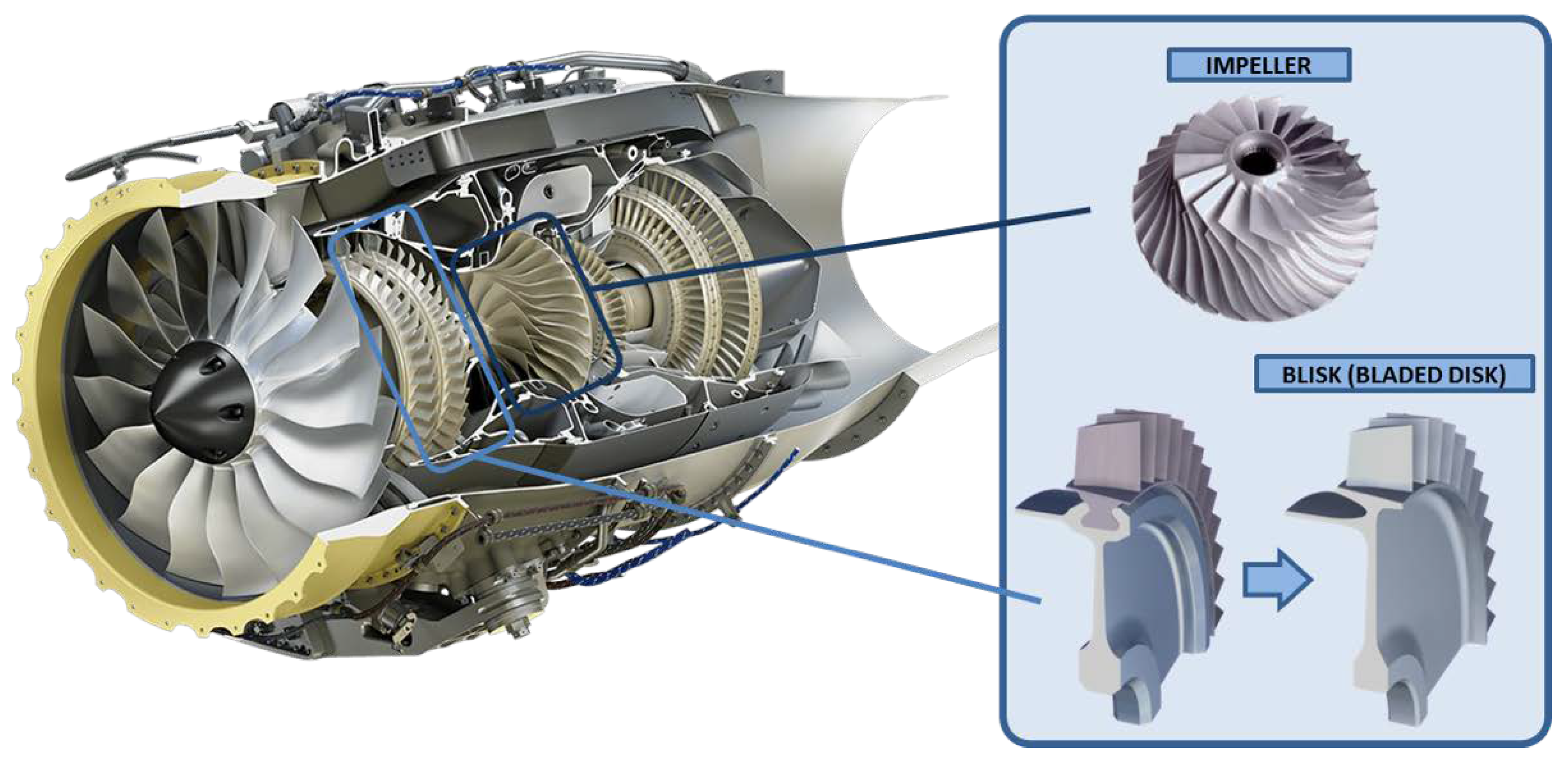
Figure 1. HF-120 turbofan engine (GE-Honda). Blisk and impeller examples [3].
Applsci 10 03063 g001
Figure 2. Integral blade rotors (IBRs) manufacturing methods subjected to material resistance and geometry [7].
Applsci 10 03063 g002
Figure 3. Production costs of 20 process chains for impeller manufacturing; (P18) is considered the conventional reference process chain [15].
Applsci 10 03063 g003
Figure 4. Material removal rates for WEDM (wire electro discharge machining) and SEDM (sink electro discharge machining) manufacturing process on thermo resistant superalloys [21].
Applsci 10 03063 g004
Figure 5. Generated optimal tool-pathstoolpaths and a shrouded blisk manufacturing by EDM [24].
Applsci 10 03063 g005
Figure 6. (a) Electro Chemical Machining (ECM) method definition for a blisk and (b) blades in Ti60 blisk using ECM [27].
Applsci 10 03063 g006
Figure 7. Impeller blades repairing process through hybrid manufacturing.
Applsci 10 03063 g007
Figure 8. High pressure compressor generic blisk specifications [4] and Ti and Ni alloys material removal rates and cutting conditions [21].
Applsci 10 03063 g008
Figure 9. Sandvik® [45] and Emuge-Franken® [47] milling cutting tool forms for IBRs manufacturing.
Applsci 10 03063 g009
Figure 10. IBRs roughing strategies: slotting, trochoidal and plunge milling.
Applsci 10 03063 g010
Figure 11. Point milling and flank milling applied to a single blade.
Applsci 10 03063 g011
Figure 12. Error estimation: tool cut position and principle of error [59].
Applsci 10 03063 g012
Figure 13. A variety of SAM tools geometries [19].
Applsci 10 03063 g013
Figure 14. Bladed disc fir-trees manufacturing using SAM [67].
Applsci 10 03063 g014
Figure 15. C-space method [89].
Applsci 10 03063 g015
Figure 16. 5-axis free-form surface approximation algorithm [99]: (a) differences between the number of patches and (b) different tool positions and geometries.
Applsci 10 03063 g016
Table 1. Patents related to super abrasive machining.
Patent Number & TitleDescriptionFigures
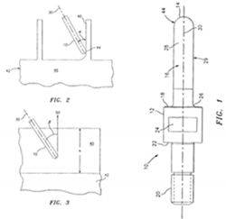
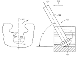
US 7144307 Point abrasive maching of nickel alloys. UTC [73].This patent develops a superabrasive manufacturing process similar to point milling strategy for nickel-based alloys. The used tool consists in a specific tool coated with abrasive material. Applsci 10 03063 i001
US 7101263 Flank superabrasive machining. UTC [74].This patent develops a new superabrasive conical tool for using flank SAM on complex geometries as turbine blades. Applsci 10 03063 i002
US 7007382 Slot machining. UTC [75].This patent presents a methodology for initial slots in fir-trees in three different stages. (1) Slot base, (2) right lateral side and (3) left lateral side. Applsci 10 03063 i003
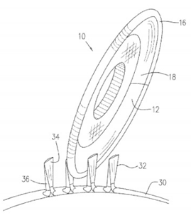
US7303461B1 Method of machining airfoils by disc tools. Pratt and Whitney [76].This patent develops a grinding peripherical strategy to remove material on airfoils discs using multi-axis simultaneous motions. Applsci 10 03063 i004
US 7789732 Superabrasive tool. UTC [77].A special abrasive machining tool for point machining in different steps. The body is composed of a tool tip abrasive coating. Applsci 10 03063 i005
US 7896728 Machining methods using superabrasive tool. UTC [78].A tool for abrasive machining with a concave abrasive coated protuberance at the tip end and a radial span at least 20% of the protuberance radius. Applsci 10 03063 i006
EP 2705926 A1 Finishing process for making blade slots in a rotor disc. Fidia SpA & GE Avo SRL [79].This patent filed a finishing process for fir trees manufacturing using a grinding tool along trochoidal paths. Applsci 10 03063 i007