Article

Investigation of Factors Affecting Sensitivity Enhancement of an Optical Fiber Probe for Microstructure Measurement Using Oblique Incident Light

1
Department of Mechanical Systems Engineering, Faculty of Environmental Engineering, The University of Kitakyushu, Fukuoka 8080135, Japan
2
Department of Mechanical Engineering, Faculty of Engineering, Kyushu University, Fukuoka 8190395, Japan
3
Department of Mechanical Engineering, Faculty of Science and Engineering, HOSEI University, Tokyo 1848584, Japan
4
Department of Technical, Division of Instrument, Kosaka Laboratory Ltd, Saitama 3410035, Japan
*
Author to whom correspondence should be addressed.
Appl. Sci. 2020, 10(9), 3191; https://doi.org/10.3390/app10093191
Submission received: 10 April 2020 / Revised: 30 April 2020 / Accepted: 30 April 2020 / Published: 3 May 2020
(This article belongs to the Section Mechanical Engineering)

Abstract

:
Recently, the demand for accuracy measurement of microstructures has been remarkable. We have been developing a measurement system for microstructures using a stylus made of an optical fiber and prisms. In this measurement system, the oblique irradiation of the laser beam was employed to detect the displacement of the stylus shaft generated by contact between the stylus tip and the measured surface, and to expand the measurable area and depth. After these evaluations, we discovered that the sensitivity was enhanced with the increase in the incident angle of the laser beam on the stylus shaft. Therefore, in this study, we focus on the effect of the incident angle of light on the measurement sensitivity. First, the enhancement sensitivity is confirmed by using the basic experimental apparatus. Next, the relationship between the incident angle of the laser beam and the sensitivity is theoretically examined using the 3D ray-tracing method. Finally, the factor of the sensitivity enhancement is analyzed using the same method. As a result, it was confirmed that the sensitivity was enhanced with the increase in the incident angle of the laser beam on the stylus shaft.

1. Introduction

Recently, the demand for accuracy measurement of microstructures has been remarkable. For example, in cases where micro-holes associated with the nozzles and semiconductor devices have diameters ranging from several micrometers to several ten micrometers, with depths ranging from several tens of micrometers to several hundred micrometers, a measurement probe of a diameter of less than 10 µm with a high-aspect-ratio is required.
Numerous papers have been issued on microstructure measurement systems that have many different kinds of probes, such as mechanical probes (e.g., elastic probes [1] and vibration applied probe [2,3]), optical probes (e.g., fiber probes [4,5], optical trapping probe [6]) and others (e.g., the atomic force microscope probe [7]). In regard to mechanical probes, the internal shape of the microstructure (e.g., micro hole) can be measured in high reproducibility. However, the probe needs to have high rigidity in order to transmit the force generated at the probe tip to the force detective sensor. Therefore, it is very difficult to develop the probe shaft with a diameter of less than few µm. The optical probes have the same problems because of the resolution limit of lenses and CCDs. The atomic force microscope has a high measurement resolution, but it cannot be applied to measure the internal shape of microstructures with high aspect ratios. For these reasons, measuring the accuracy of micro holes and grooves with diameters and widths smaller than a few µm in diameter is extremely difficult because of the difficulty of stylus manufacture and sensing methods with low measurement forces.
We have been developing a measurement system for microstructures using a stylus made of an optical fiber and prisms [8]. The probe shaft and tip are manufactured using a wet etching device and CO2 laser processing [9]. In our previous paper [8], the measurement system was improved by using the prisms to expand the measurement region and depth, after which we examined the repeatability of measurement in the X-,Y- and Z-directions, using a pin gauge with a diameter of 100 µm in the X- and Y-directions and using a step height standard with a height of 189 nm in the Z-direction. In addition, the paper has the result of the long-term drift for 180 min and the expanded uncertainty. In this measurement system, the oblique irradiation of the laser beam was employed to detect the displacement of the stylus shaft generated by contact between the stylus tip and the measured surface, and to expand the measurable area and depth. The incident angle was set to 26.5°. After these evaluations, we discovered that the sensitivity was enhanced with the increase in the incident angle of the laser beam on the stylus shaft. Therefore, in this study, we focus on the effect of the incident angle of light on the measurement sensitivity. First, the enhancement sensitivity is confirmed by using the basic experimental apparatus. Next, the relationship between the incident angle of the laser beam and the sensitivity is theoretically examined using the 3D ray-tracing method. Finally, the factor of the sensitivity enhancement is analyzed using same method.

2. Configuration of the Optical Fiber Probe

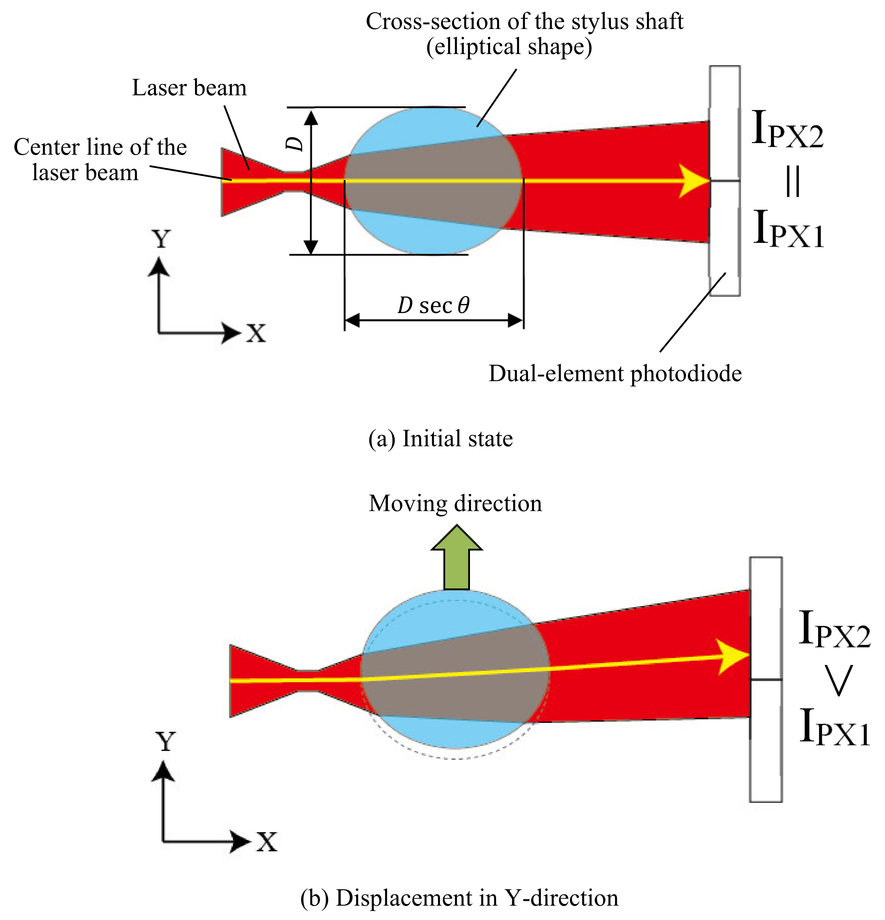
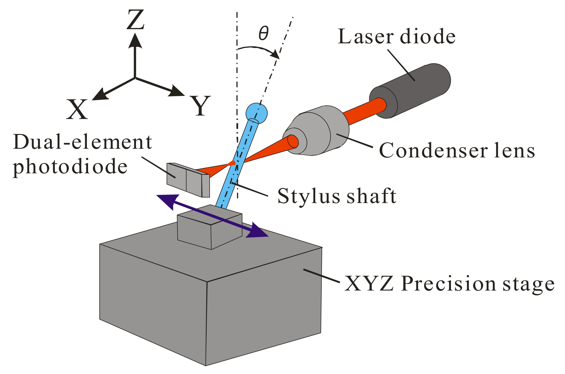
Figure 1 shows the optical system of the fiber probe. The probing system is composed of the stylus shaft and tip made of an optical fiber, two focused beams and two dual-element photodiodes in the X- and Y-directions. The probe shaft and tip are manufactured using a wet etching device and CO2 laser processing [9]. The axes of two laser beams are inclined θ ° to XY plane. The laser beams are reflected in an upward direction by the prisms. This makes all optical systems install above the stylus and measured surface, and it is possible to avoid the interference between the optical system and measured surface [8]. The intermediate part of the stylus shaft is then irradiated with the focused laser beams in the X- and Y-directions. The length of the stylus shaft from the fixing jig to the stylus tip is 2 mm, and the projecting length of the stylus shaft from the lower end face of the prisms is 1 mm. The stylus tip diameter is within the limit from 1 µm to several 100 µm. Therefore, the stylus can be employed for measuring the microstructures, such as micro-holes with a depth of 1 mm and a diameter of a few µm [10]. In cases where the stylus tip makes contact with the surface being measured, the deflection occurs in the shaft, as shown in Figure 1. Figure 2 shows the section A-A in Figure 1, which shows the laser irradiation position and the locus of the laser beam in the Y-direction. The focused laser beam passes through the inside of the shaft and is detected by the dual-element photodiode. The focus point of the laser beam coincides with that of the stylus shaft as a rod lens. When the diameter of the stylus shaft is 70 µm, the distance from the focus point of the laser beam to the surface of the stylus shaft is approximately 20 µm. The diameter of the laser beam is approximately 15 µm where the laser beam is incident on the surface of the stylus shaft. The laser beam intensities measured by respective region of the dual-element photodiode are converted into voltage signals and are defined as IPX1 and IPX2 (V). As indicated in Figure 2a, in cases where the stylus tip does not make contact with the surface being measured, the laser beam intensities detected by respective region of the dual-element photodiode are equal (IPX1 = IPX2). In cases where the stylus tip hits on the surface being measured in the positive Y-direction, the stylus shaft is deflected in the same direction and the cross-section of the stylus shaft emitted by the laser beam is also displaced, as shown in Figure 2b. Consequently, the refraction angle of the laser beam passing through the inside of the stylus shaft in the X-direction varies and the laser beam is emitted toward the positive Y-direction because of the displacement of the irradiated part of the stylus shaft, and the light intensities of respective regions of the dual-element photodiode become unequal (IPX2 > IPX1), as indicated in Figure 2b. The output signals IX in the X-direction using IPX1 and IPX2 are defined in Equation (1). The contact between the stylus tip and the surface of the microstructure in the Y-direction is determined when the output signal IX exceeds the threshold value.
I X = I PX 1 I PX 2
Similarly, the contact between the tip and the measured surface in the X-direction can be detected by using the laser diode and dual-element photodiode placed in the orthogonal Y-direction. When the tip comes into contact with the horizontal plane in the Z-direction, the stylus shaft is buckled and then deflected.
In this measurement principle, the light passing through the inside of the stylus shaft is refracted by the elliptical cross-section of the stylus shaft, as depicted in Figure 2. This elliptical shape (the lengths of the major and minor axis in Figure 2a) changes depending on the incident angle θ of the laser beam in Figure 1 and affects the measurement sensitivity. Therefore, the effect of the incident angle θ of the laser beam on the measurement sensitivity is examined both experimentally and theoretically.

3. Effect of Incident Angle of the Light on the Measurement Sensitivity

As shown in Figure 1, the laser beam is obliquely incident on the stylus shaft; therefore, we now discuss the relationship between incident angle and measurement sensitivity both experimentally and theoretically. First, the enhancement sensitivity is confirmed by using the basic experimental apparatus. Next, the relationship between the incident angle of the laser beam and the sensitivity is theoretically examined using the 3D ray-tracing method. Finally, the factor of the sensitivity enhancement is analyzed using same method.

3.1. Experimental Assessment of Sensitivity

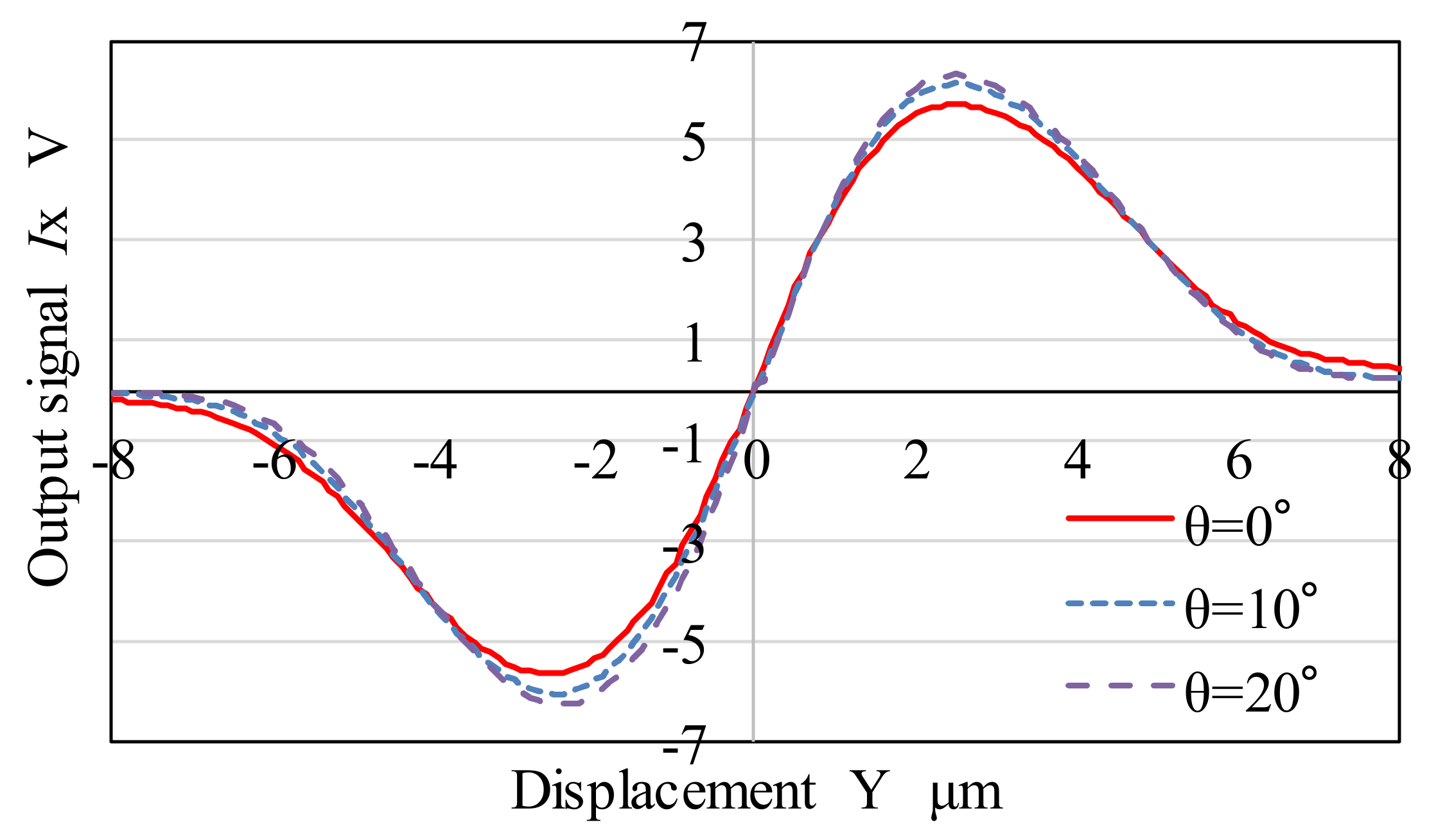
Figure 3 shows the experimental apparatus for measuring the sensitivity of the optical fiber probe. The experimental apparatus consists of the laser diode (57108-L, Edmund, Barrington, NJ, USA) with a wavelength of 630 nm and a light output of 5 mW, the condenser lens (SPAHL-5, SIGMAKOKI CO., LTD., Tokyo, Japan), the dual-element photodiode (S5870, Hamamatsu Photonics K.K., Shizuoka, Japan) and the XYZ precision stage (P-611.3S, Physik Instrumente (PI) GmbH & Co. KG, Karlsruhe, Germany). The numerical aperture of the condenser lens is 0.13. The closed-loop resolution of the XYZ precision stage is 1 nm. The laser beam was irradiated on the stylus shaft (of 70 µm diameter) placed at an angle θ with respect to the Z-axis, as indicated in Figure 3. The experiment was conducted using the passive vibration isolating table in the chamber controlled to 20 °C ±   0.1   . The light transmitted through the inside of the stylus shaft was detected by the dual-element photodiode. When the stylus shaft was displaced from −2.5 to 2.5 µm in the Y-direction by using the precision piezo stage, the output signal IX as defined in Equation (1) was recorded. Figure 4 shows the experimentally measured values of IX for θ = 0°, 10° and 20°. The inclination of the curves near the origin in Figure 4 indicates the measurement sensitivity. That is, it is 3.61, 3.80 and 4.04 V/µm in the range of −1 to 1 µm in the displacement Y for θ = 0°, 10° and 20°, respectively. The sensitivity for θ = 10° and 20° is enhanced by 5 and 12%, respectively, compared to 0°.
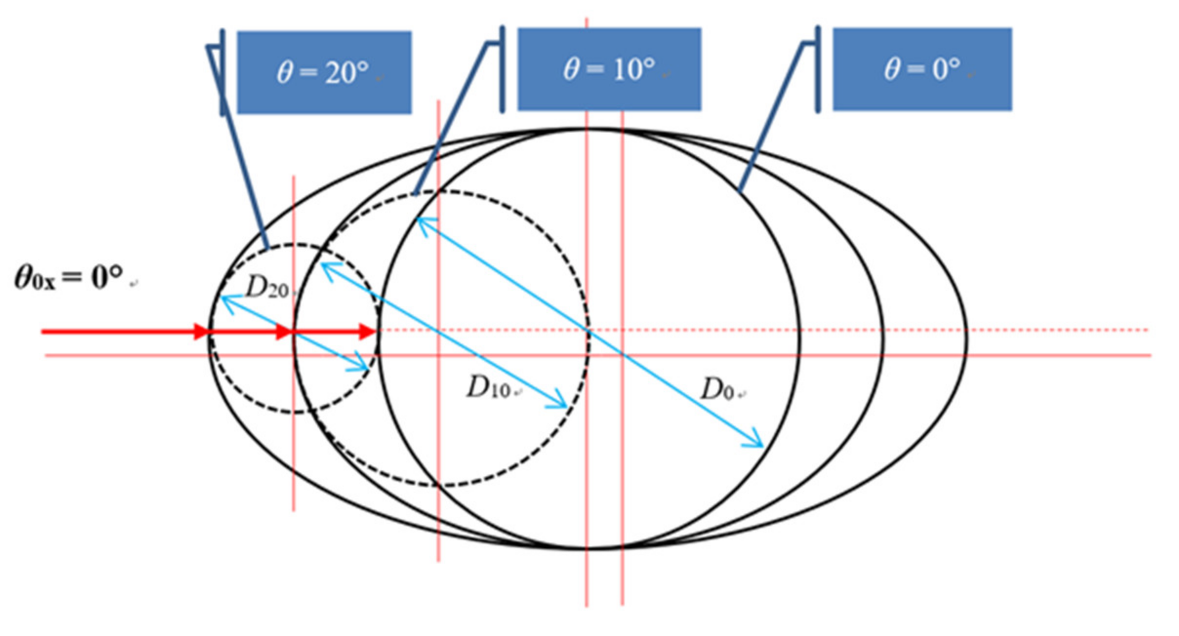
It is evident here that the sensitivity increases with the increase in the incident angle θ. For θ = 0°, the cross-sectional shape of the stylus shaft through which the incident laser beam passed in the XY plane was circular. However, the stylus shaft assumed an elliptical sectional shape for θ ≠ 0, as shown in Figure 2. The difference between the major and minor axes of the elliptical cross-section increases with the increase in θ. Therefore, the enhancement of sensitivity may be attributed to the increase in the cross-sectional curvature of the stylus shaft and the increase in the refraction angle.

3.2. Simulation Assessment of Sensitivity

The relationship between the incident angle θ of the laser beam and the sensitivity was theoretically examined using the 3D ray-tracing method. The laser beam was assumed to have an ideal Gaussian intensity distribution. First, random numbers with a Gaussian intensity distribution were generated using the Box–Muller method [11], and one hundred million rays having this distribution were irradiated from the lens. After that the rays were traced through the stylus shaft, and the number of rays received at the respective photodiode was calculated. Here, the intensities received by respective photodiode were expressed in terms of the relative intensities for all the rays as IX_SIM (%). Figure 5 shows schematic diagram of the ray-tracing method. The cross-section of the stylus shaft has an elliptical shape that changes with the incident angle θ of the laser beam. Table 1 and Table 2 list the conditions of ray-tracing and the parameters used for ray-tracing. The coordinate, P3(x3, y3, z3), of the laser irradiation position on the photodiode can be calculated by Equations (2)–(4).
x 3 = L 1 + D sec θ 2
y 3 = y 2 + L 1 x 2 + D sec θ 2 tan θ 2 X
z 3 = z 2 + x 3 x 2 tan θ 2 Z
In the measurement system, when the stylus tip makes contact with the surface being measured and the output signal IX is equal to the threshold value, which means that the laser irradiation position of the stylus shaft is displaced by 30 nm, the contact between the stylus tip and the surface being measured is detected and the coordinates of the XYZ precision stage are recorded. The tilt angle of the stylus shaft of the laser irradiation part after this contact detection is 3.1 × 10 3 degrees. This angle is considerably smaller than the laser irradiation angle of 10, 20 and 30 degrees, so the effect of stylus tilt can be ignored in the simulation.
Figure 6 shows the results of the ray-tracing when the stylus shaft was displaced from −2.5 to 2.5 µm in the Y-direction with the incident angle θ of the laser beam as a parameter. The sensitivity in the range of −1 to 1 µm in the Y-direction is 17.1, 17.5, 18.5 and 20.1%/µm for θ = 0°, 10°, 20 and 30°, respectively. It is enhanced by 2.3, 8.2, and 17.5% for θ = 10°, 20° and 30°, respectively, compared to 0°. It is confirmed here that the sensitivity increases with the increase in the incident angle θ, which is consistent with the experimental results. However, the position of displacement Y, where the experimental output signal IX is minimum or maximum, is slightly different from that of IX_SIM in the simulation. This may be because the experimental parameters such as the diameter of the stylus shaft and the lens performance do not exactly match the theoretical parameters in the simulation.
Consequently, it is possible to increase the measurement sensitivity. Therefore, because the sensitivity of the optical fiber probe increases with the increase in the incident angle of the laser beam on the stylus shaft, it is desirable that the stylus shaft is irradiated at as large an incident angle as possible by using the prism with a mirror.

3.3. Discussion Associated with Enhancement of Sensitivity

As a factor of the sensitivity enhancement, the relationship between the stylus shaft diameter and the coordinate of irradiation position on the dual-element photodiode is examined when the stylus shaft is displaced in the Y-direction. Here, the stylus shaft diameter is considered the curvature radius of the elliptical shape of the oblique cross-section of stylus at the laser beam oblique irradiation position of stylus surface (Figure 7). Figure 8 shows the simulation result of coordinate y3 of the three rays passing through each focal point of the stylus shaft as a rod lens for θ0X = −7.47°, 0° and 7.47° (Corresponding to both sides and the center of the expanding laser beam) on the dual-element photodiode, while the stylus shaft was displaced 0.03 µm in the Y-direction. The horizontal and vertical axes show the diameter of the stylus shaft and the coordinate y3, respectively. In this simulation, the shape of the cross-section of the stylus shaft is a perfect circle. As shown in Figure 8, the center of the laser beam spot is shifted to 0 (the center of the dual-element photodiode) as the diameter of the stylus shaft increases. This means that the sensitivity decreases as the diameter of the stylus shaft increases.
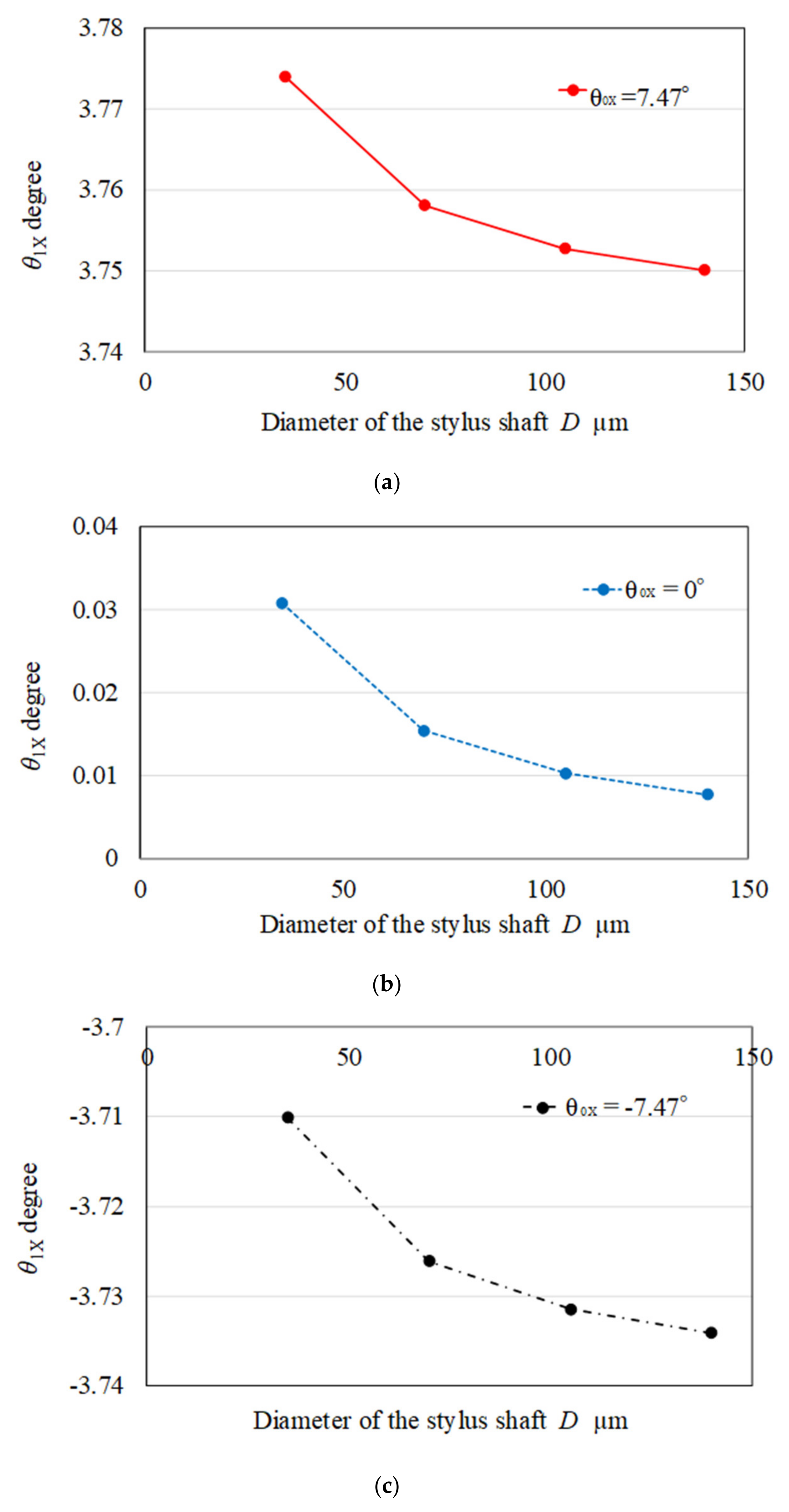
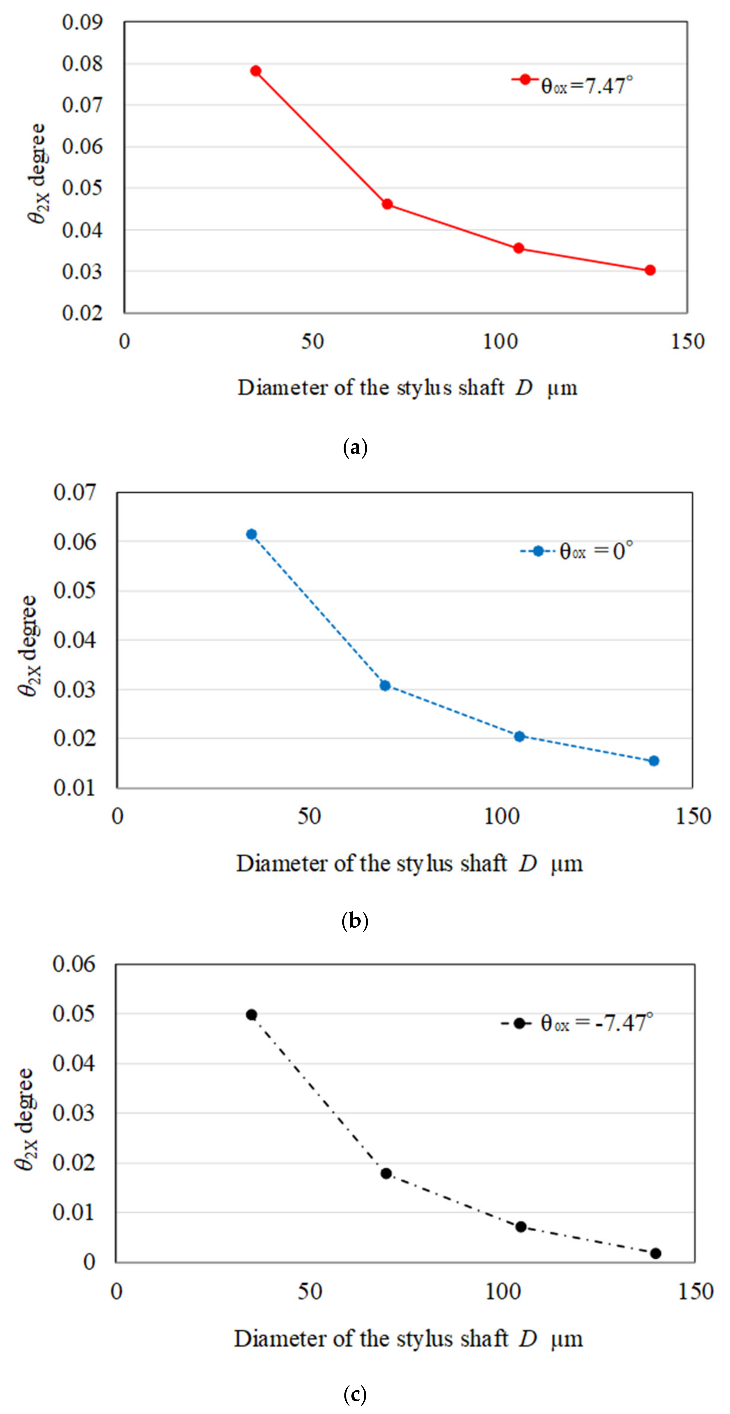
Figure 9 shows the ray-tracing result of tilt angle θ1X of the three rays for θ0X = −7.47°, 0° and 7.47° when the stylus shaft was displaced 0.03 µm in the Y-direction. The tilt angle θ1X decreases as the diameter D of the stylus shaft increases. Figure 10 shows the ray-tracing result of tilt angle θ2X of the three rays for θ0X = −7.47°, 0° and 7.47° when the stylus shaft was displaced 0.03 µm in the Y-direction. The tilt angle θ2X also decreases as the diameter D of the stylus shaft increases. Similarly, the refraction angle of the laser beam decreases with increasing the radius of curvature of the stylus surface. If the refraction angle decreases, the sensitivity also decreases because the laser spot shifts to the center of the dual-element photodiode as indicated in Figure 8. In other words, when the stylus shaft is irradiated obliquely by the laser beam, the stylus cross-section, in the direction of the beam passage, changes to the elliptical shape and the radius of curvature of the stylus surface decreases, as shown in Figure 7. This effect leads to the enhancement of the sensitivity.

4. Conclusions

We have presented a microstructure measurement system using a stylus made of an optical fiber and prisms. In this measurement system, the oblique irradiation of the laser beam was employed to detect the displacement of the stylus shaft generated by contact between the stylus tip and the measured surface. In this study, the effect of the incident angle of the laser beam on the measurement sensitivity was examined both experimentally and theoretically. As a result of experiment, it was confirmed that the sensitivity for inclination angle of the laser beam θ = 10° and 20° was enhanced by 5 and 12%, respectively, compared to 0°, and that the sensitivity was enhanced with the increase in the incident angle of the laser beam on the stylus shaft. As a result of simulation, the sensitivity was enhanced by 2.3, 8.2 and 17.5% for θ = 10°, 20° and 30°, respectively, compared to 0°. Although the increased rates of sensitivity are slightly different, it was confirmed that the simulation results showed the same tendency as the experimental results. In addition, the refraction angle of the laser beam decreases with increasing the radius of curvature of stylus surface. If the refraction angle decreases, the sensitivity also decreases because the laser spot shifts to the center of the dual-element photodiode. In other words, when the stylus shaft is irradiated obliquely by the laser beam, the stylus cross-section, in the direction of beam passage, changes to the elliptical shape and the radius of curvature of stylus surface decreases. We confirmed that this effect leads to the enhancement of the sensitivity by ray-tracing simulation results. This makes it possible to measure even smaller shape changes of the measured surface without making major design changes to the measurement system.

Author Contributions

Conceptualization, H.M.; methodology, I.Y.; validation, A.K., T.S. and I.Y.; formal analysis, A.K. and T.S.; investigation, Y.H. and H.H.; data curation, K.U.; writing—original draft preparation, H.M.; writing—review and editing, A.K., T.S. and I.Y.; funding acquisition, H.M. All authors have read and agreed to the published version of the manuscript.

Funding

This research was funded by a research grant from the METI Supporting Industry Program and JSPS KAKENHI Grant Number 26420392.

Conflicts of Interest

The authors declare no conflict of interest.

References

  1. Albalaihid, K.; Lawes, S.; Kinnell, P. Variable stiffness probing systems for micro-coordinate measuring machines. Precis. Eng. 2016, 43, 262–269. [Google Scholar] [CrossRef] [Green Version]
  2. Huang, Q.; Chen, C.; Wu, K.; Zhang, L.; Li, R.; Fan, K.-C. A Three-Dimensional Resonant Triggering Probe for Micro-CMM. Appl. Sci. 2017, 7, 403. [Google Scholar] [CrossRef] [Green Version]
  3. Ito, S.; Kikuchi, H.; Chen, Y.; Shimizu, Y.; Gao, W.; Takahashi, K.; Kanayama, T.; Arakawa, K.; Hayashi, A. A micro-coordinate measurement machine (CMM) for large-scale dimensional measurement of micro-slits. Appl. Sci. 2016, 6, 156. [Google Scholar] [CrossRef] [Green Version]
  4. Cui, J.; Li, J.; Feng, K.; Tan, J.; Zhang, J. A 3D fiber probe based on orthogonal micro focal-length collimation and fiber Bragg grating. Meas. Sci. Technol. 2016, 27, 074005. [Google Scholar] [CrossRef]
  5. Muralikrishnan, B.; Stone, J.A.; Stoup, J.R. Fiber deflection probe for small hole metrology. Precis. Eng. 2006, 30, 154–164. [Google Scholar] [CrossRef]
  6. Takaya, Y.; Michihata, M.; Hayashi, T. Scanning type microrobe for displacement measurement based on standing wave detection using an optically trapped particle. Int. J. Autom. Technol. 2011, 5, 395–402. [Google Scholar] [CrossRef]
  7. Felix, M.; Alain, K. Development of a 3D-AFM for ture 3D measurements of nanostructures. Meas. Sci. Technol. 2011, 22, 094009. [Google Scholar] [CrossRef]
  8. Murakami, H.; Katsuki, A.; Sajima, T.; Uchiyama, K.; Yoshida, I.; Hamano, Y.; Honda, H. Development of measurement system for microstructures using an optical fiber probe: Improvement of measurable region and depth. Meas. Sci. Technol. 2020, 31, 075902. [Google Scholar] [CrossRef]
  9. Murakami, H.; Katsuki, A.; Sajima, T.; Uchiyama, K. Fabrication of an ultra-small-diameter optical fiber probe using an acid-etch technique and a CO2 laser for 3D micro metrology. Int. J. Autom. Technol. 2017, 11, 699–706. [Google Scholar] [CrossRef]
  10. Murakami, H.; Katsuki, A.; Sajima, T.; Tokuoh, N.; Fukuda, M. Development of a system for 3-D micro metrology using an ultra-small-diameter optical fiber probe. Proc. Am. Soc. Precis. Eng. 2014, 59, 63–66. [Google Scholar]
  11. Press, W.H. Numerical Recipes in C; Cambridge University Press: Cambridge, UK, 1988; p. 216. [Google Scholar]
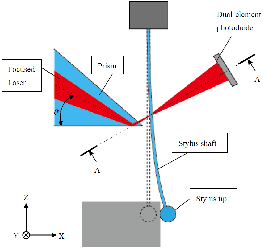
Figure 1. Optical system of the fiber probe.
Applsci 10 03191 g001
Figure 2. Section A-A in Figure 1.
Applsci 10 03191 g002
Figure 3. Experimental apparatus for measuring the sensitivity of the optical fiber probe (the stylus shaft is inclined in the X-direction).
Applsci 10 03191 g003
Figure 4. Experimentally measured values of IX for angles θ = 0°, 10° and 20° (displacement of the stylus shaft along Y-axis = ±2.5 µm).
Applsci 10 03191 g004
Figure 5. Schematic diagram of the ray-tracing method.
Applsci 10 03191 g005
Figure 6. Simulated values of IX for θ = 0°, 10°, 20° and 30° (displacement of the stylus shaft along Y-axis = ±2.5 µm).
Applsci 10 03191 g006
Figure 7. Schematic diagram of the stylus shaft diameter considered the curvature radius of elliptical shape of oblique cross-section of stylus at the laser beam oblique irradiation position of stylus surface.
Applsci 10 03191 g007
Figure 8. Simulated values of y3 for θ0X = −7.47°, 0° and 7.47° (displacement of the stylus shaft along Y-axis = 0.03 µm).
Applsci 10 03191 g008
Figure 9. Simulated values of θ1X (displacement of the stylus shaft along Y-axis = 0.03 µm). (a) θ0X = 7.47°; (b) θ0X = 0°; (c) θ0X = −7.47°.
Applsci 10 03191 g009
Figure 10. Simulated values of θ2X (displacement of the stylus shaft along Y-axis = 0.03 µm). (a) θ0X = 7.47°; (b) θ0X = 0°; (c) θ0X = −7.47°.
Applsci 10 03191 g010
Table 1. Conditions of ray-tracing.
Light SourceWavelength: 630 nm
Diameter of the stylus shaft, D70 µm
Refractive index of optical fiber (stylus shaft)1.457
Length from planes 0 to 1, L020 µm
Length from planes 2 to 3, L140 mm
Numerical aperture of the lens0.13
Displacement of the stylus shaft, Y–8–8 µm
Diameter of laser spot, DS10 µm
Region of the dual-element photodiode5 × 10 mm
Table 2. Parameters used for ray-tracing.
X, Y, Z: Coordinates Used for Ray-Tracing
D: Diameter of the stylus shaft
L0, L1: Length from between plane 0 to plane 1, plane 2 to plane 3
n0, n1: Refractive indices of the air and optical fiber (stylus)
W1, W2, W3: Heights of laser beam at respective planes
θ 0 X , θ 1 X θ 2 X θ 3 X : Inclination angles of rays in the X-direction
θ 0 Z , θ 1 Z θ 2 Z : Inclination angles for rays in the Z-direction
β , γ : Angles between the normal line at the laser irradiation position of the stylus shaft and X-axis
θ a , θ c : Incident angle
θ b , θ d : Refracting angle
Δ 1 : Length from a laser irradiation position on the surface of the stylus shaft to plane-1