Frost Resistance of Coal Gangue Aggregate Concrete Modified by Steel Fiber and Slag Powder

Abstract
:1. Introduction
2. Materials and Methods
2.1. Materials
2.1.1. Binding Materials
2.1.2. Coal Gangue Aggregate
2.1.3. Steel Fibers
2.2. Specimens Preparation
2.2.1. Mixture Proportions
2.2.2. Mixing Process
- Mix the fine and coarse aggregate (dry-condition) for 30 s;
- Add steel fibers (HESF, USF, or CPSF) and mix them for 30 s;
- Add cement and mix for 30 s;
- Add the mixing water with superplasticizer into the dry mixture and mix them well for 3 min (with slag powder) or 5 min (with steel fiber).
2.3. Experimental Methods
2.3.1. F-T Test
- After being cured for 24 days, concrete specimens were taken out of the chamber and soaked in water at about 20 °C for 4 days before the F-T test.
- The specimens were dried, marked, weighed, and then placed them into a rubber box in the F-T chamber. Water was added to the rubber box to about 2 cm above the top of the specimens;
- Temperatures of the center and the surface of the samples were monitored by using embedded temperature sensor.
2.3.2. Evaluation Index of Frost Resistance
- (1)
- Compressive Strength Loss
- (2)
- Splitting tensile strength loss
- (3)
- Mass loss
- (4)
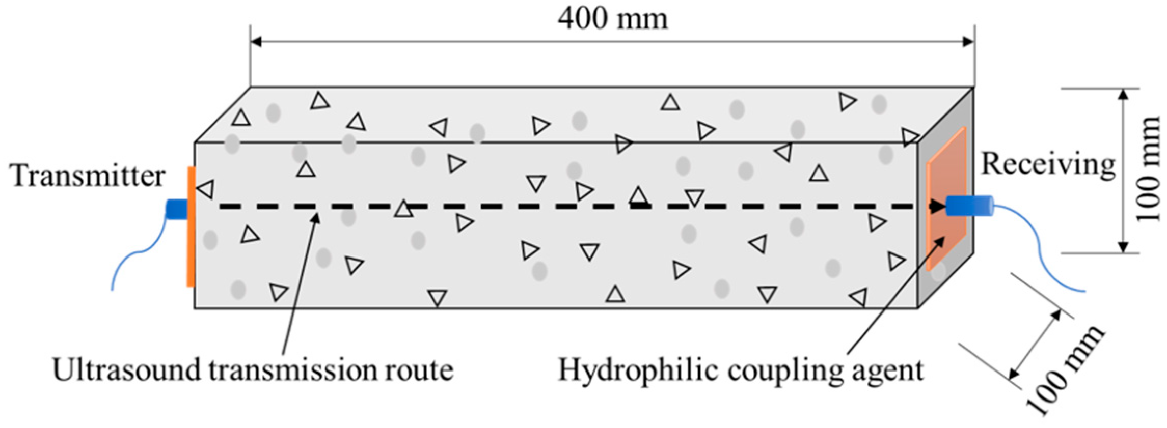
- RDME
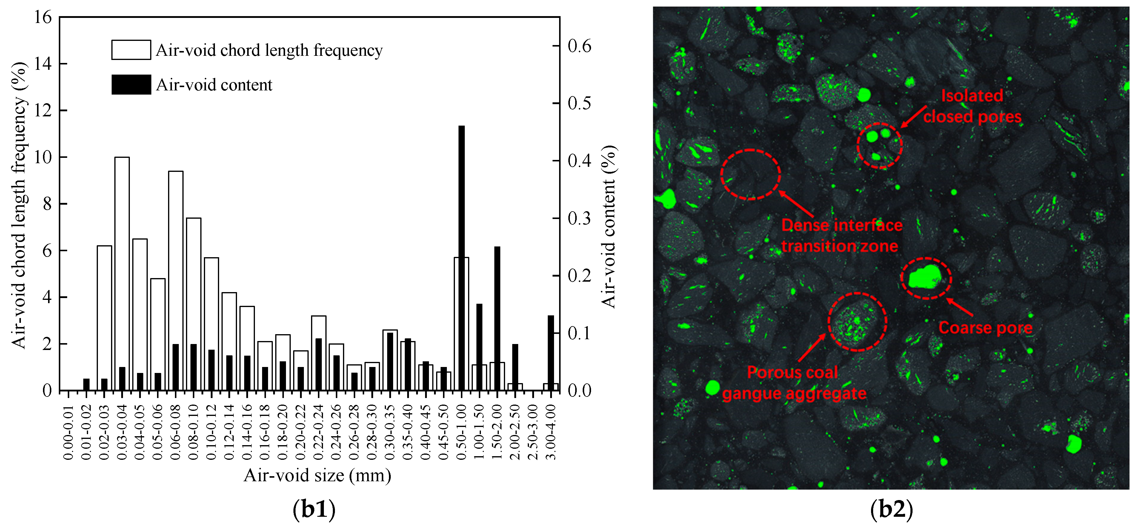
2.3.3. Air-Void Characteristics before F-T Cycles
3. Results and Discussion
3.1. Effect of Steel Fiber on Frost Resistance
3.1.1. Compressive Strength Loss
3.1.2. Splitting Tensile Strength Loss
3.1.3. Mass Loss
3.1.4. RDME
3.2. Effect of Slag Powder
3.2.1. Compressive Strength Loss
3.2.2. Splitting Tensile Strength Loss
3.2.3. Mass Loss
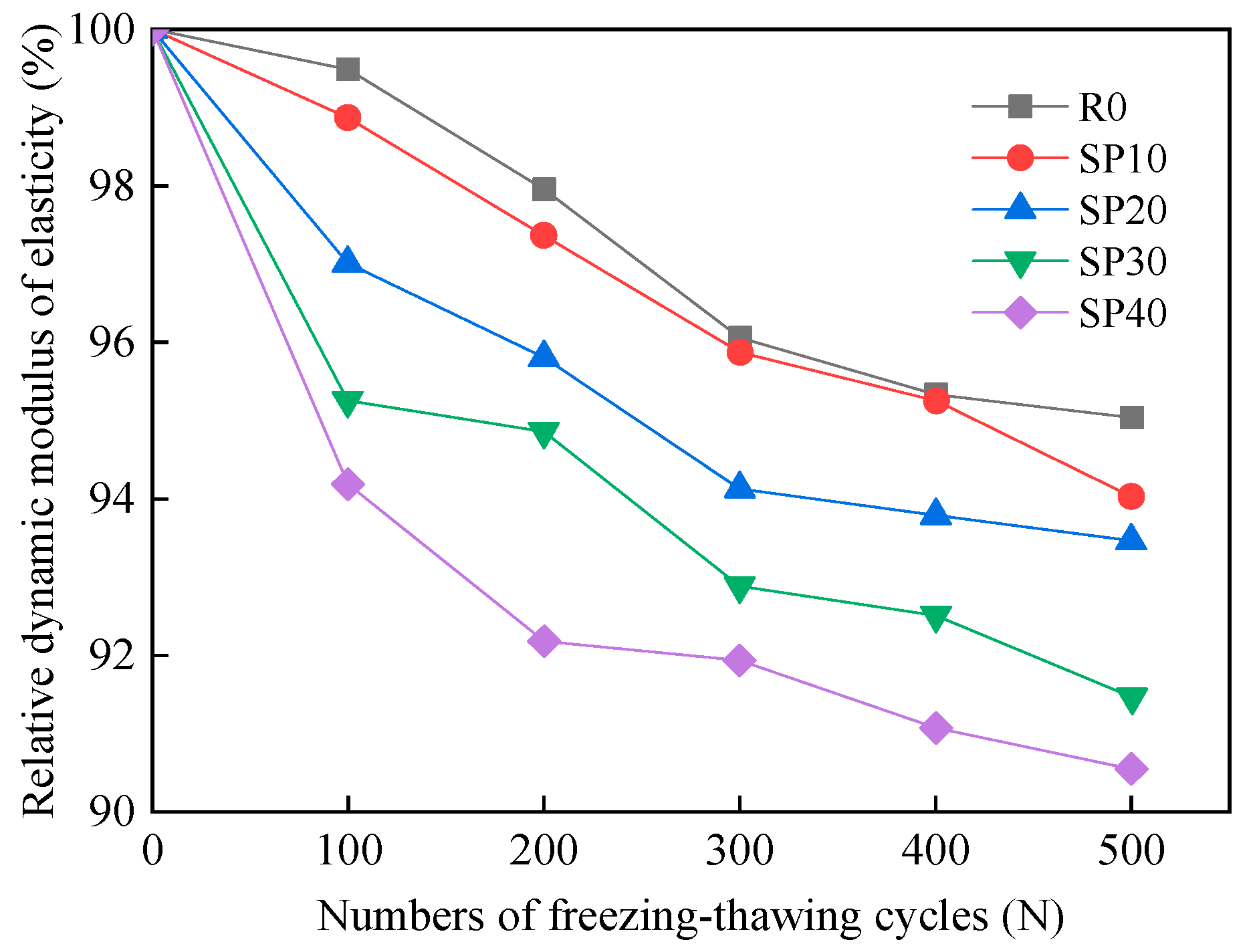
3.2.4. RDME
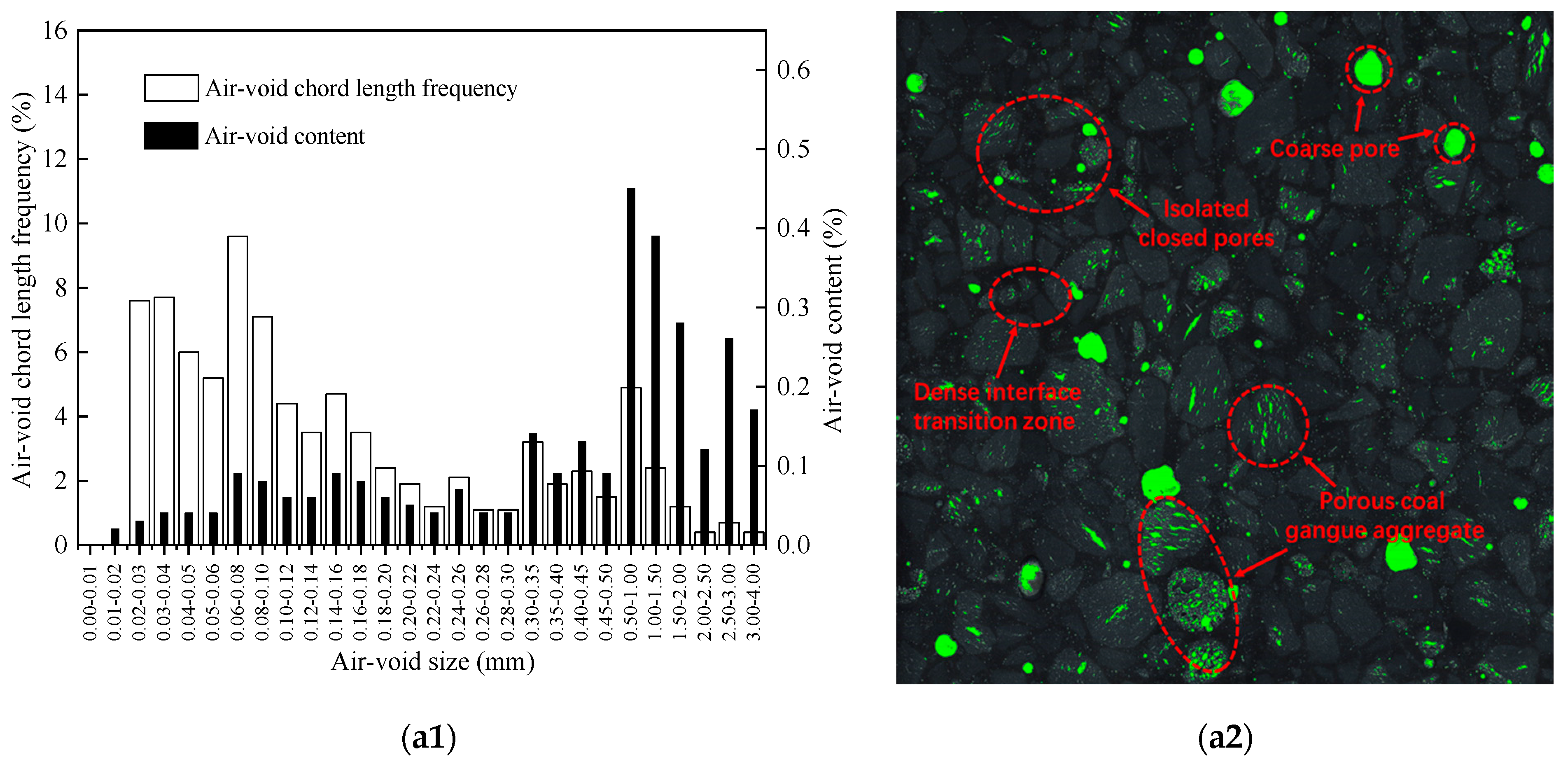
3.3. Air-Void Characteristics before F-T Test
3.3.1. Effect of Steel Fiber Type on Air-Void Structure
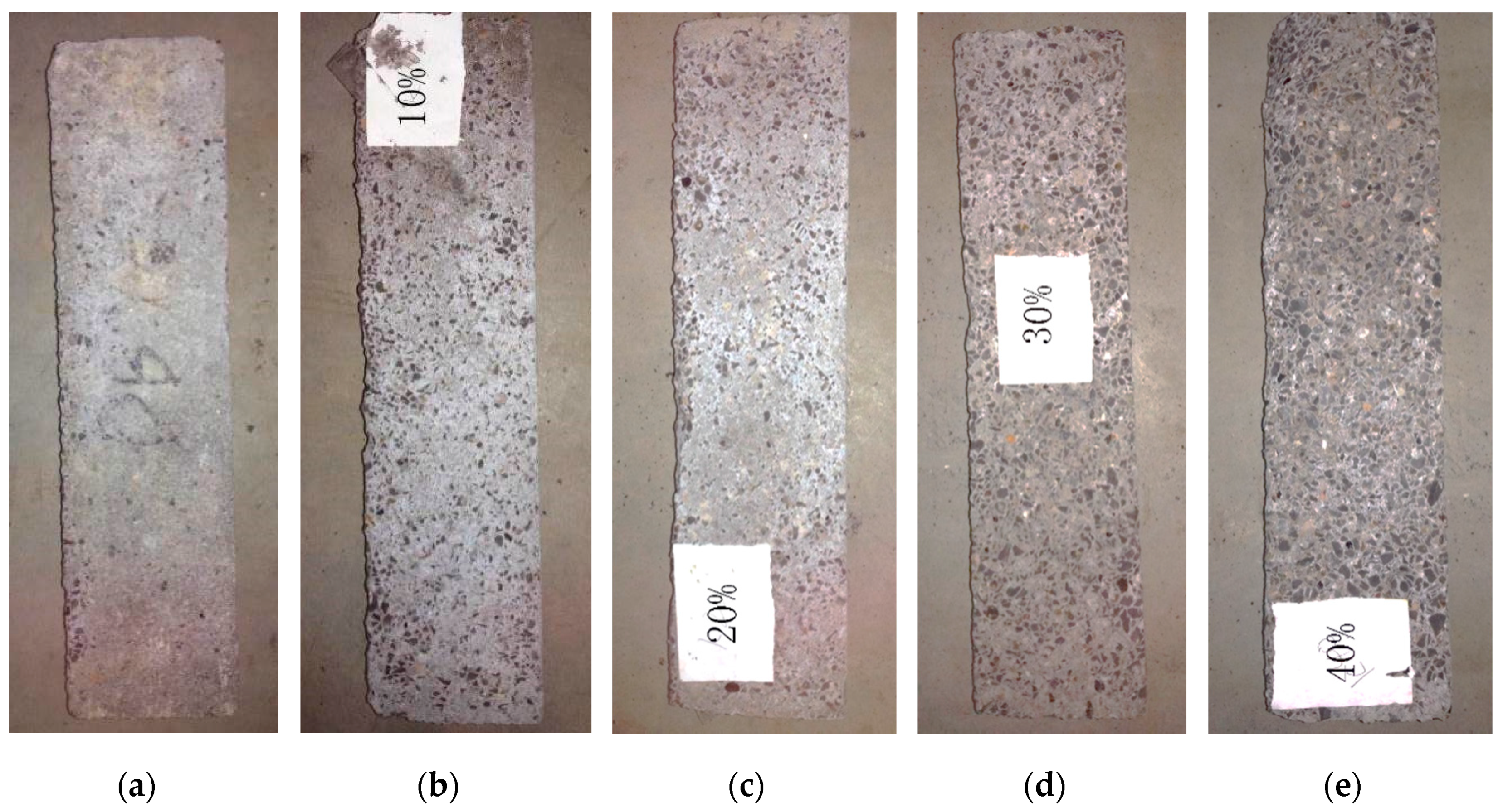
3.3.2. Effect of Slag Powder Content on Air-Void Structure
4. Conclusions
- After adding proper types and amounts of steel fibers, the compressive strength loss and splitting tensile strength loss of CGAC reduced, which was beneficial to its frost resistance. However, the mass loss of CGAC increased. Compared with other mix proportions, CGAC with 1 vol.% USF suffered the smallest compressive strength loss and splitting tensile strength loss, with values of 14.2% and 14.7%, respectively.
- The RDME of steel-fiber-reinforced CGAC fluctuated between 100.0% and 103.4% after the F-T test when the content of steel fiber was no less than 1 vol.%, which may be due to the speed change of ultrasound in CGAC or other factors. Thus, the RDME tested by the ultrasonic method may not be suitable to evaluate the frost resistance of steel-fiber-reinforced CGAC.
- The effect of slag powder on frost resistance of CGAC at an early age was not obvious. This may be due to the slow pozzolanic reaction of slag powder and less hydration products filling the concrete pores, as the cement was partially replaced by unactivated slag powder.
- The addition of HESF can obviously optimize the internal structure of CGAC. Just 1 vol.% HESF can increase the quantity and specific surface area of air-voids by 27.8% and 9.9%, respectively, and decrease the spacing factor and mean chord length of air-voids by 19.6% and 17.7%, respectively, thus improving the frost resistance of steel-fiber-reinforced CGAC. However, the slag powder cannot effectively optimize the air-voids structure of CGAC at an early age.
Author Contributions
Funding
Acknowledgments
Conflicts of Interest
References
- Liu, K.; Zhang, X.; Chen, Y. Extraction of coal and gangue geometric features with multifractal detrending fluctuation analysis. Appl. Sci. 2018, 8, 463. [Google Scholar] [CrossRef] [Green Version]
- Querol, X.; Izquierdo, M.; Monfort, E.; Álvarez, E.; Font, O.; Moreno, T.; Alastuey, A.; Zhuang, X.; Lu, W.; Wang, Y. Environmental characterization of burnt coal gangue banks at Yangquan, Shanxi Province, China. Int. J. Coal. Geol. 2008, 75, 93–104. [Google Scholar] [CrossRef]
- Yang, J.; Yang, B.; Yu, M. Pressure Study on Pipe Transportation Associated with Cemented Coal Gangue Fly-Ash Backfill Slurry. Appl. Sci. 2019, 9, 512. [Google Scholar] [CrossRef] [Green Version]
- Wang, S.; Luo, K.; Wang, X.; Sun, Y. Estimate of sulfur, arsenic, mercury, fluorine emissions due to spontaneous combustion of coal gangue: An important part of Chinese emission inventories. Environ. Pollut. 2016, 209, 107–113. [Google Scholar] [CrossRef] [PubMed]
- Bian, Z.; Dong, J.; Lei, S.; Leng, H.; Mu, S.; Wang, H. The impact of disposal and treatment of coal mining wastes on environment and farmland. Environ. Geol. 2009, 58, 625–634. [Google Scholar] [CrossRef]
- Zhao, C.; Luo, K. Sulfur, arsenic, fluorine and mercury emissions resulting from coal-washing byproducts: A critical component of China’s emission inventory. Atmos. Environ. 2017, 152, 270–278. [Google Scholar] [CrossRef]
- Sun, Y.; Fan, J.; Qin, P.; Niu, H. Pollution extents of organic substances from a coal gangue dump of Jiulong Coal Mine, China. Environ. Geochem. Health 2009, 31, 81–89. [Google Scholar] [CrossRef]
- Jabłońska, B.; Kityk, A.V.; Busch, M.; Huber, P. The structural and surface properties of natural and modified coal gangue. J. Environ. Manag. 2017, 190, 80–90. [Google Scholar] [CrossRef]
- Li, X.; Zhang, Q. Study on Damage Evolution and Resistivity Variation Regularities of Coal Mass under Multi-Stage Loading. Appl. Sci. 2019, 9, 4124. [Google Scholar] [CrossRef]
- Liu, H.; Liu, Z. Recycling utilization patterns of coal mining waste in China. Resour. Conserv. Recycl. 2010, 54, 1331–1340. [Google Scholar] [CrossRef]
- Zhou, C.; Liu, G.; Wu, S.; Lam, P.K.S. The environmental characteristics of usage of coal gangue in bricking-making: A case study at Huainan, China. Chemosphere 2014, 95, 274–280. [Google Scholar] [CrossRef] [PubMed]
- Wang, J.; Qin, Q.; Hu, S.; Wu, K. A concrete material with waste coal gangue and fly ash used for farmland drainage in high groundwater level areas. J. Clean. Prod. 2016, 112, 631–638. [Google Scholar] [CrossRef]
- Colombo, I.G.; Colombo, M.; di Prisco, M. Tensile behavior of textile reinforced concrete subjected to freezing–thawing cycles in un-cracked and cracked regimes. Cem. Concr. Res. 2015, 73, 169–183. [Google Scholar] [CrossRef]
- Vega-Zamanillo, Á.; Juli-Gándara, L.; Calzada-Pérez, M.Á.; Teijón-López-Zuazo, E. Impact of Temperature Changes and Freeze—Thaw Cycles on the Behaviour of Asphalt Concrete Submerged in Water with Sodium Chloride. Appl. Sci. 2020, 10, 1241. [Google Scholar] [CrossRef] [Green Version]
- Li, D.; Song, X.; Gong, C.; Pan, Z. Research on cementitious behavior and mechanism of pozzolanic cement with coal gangue. Cem. Concr. Res. 2006, 36, 1752–1759. [Google Scholar] [CrossRef]
- Zhang, N.; Sun, H.; Liu, X.; Zhang, J. Early-age characteristics of red mud–coal gangue cementitious material. J. Hazard. Mater. 2009, 167, 927–932. [Google Scholar] [CrossRef]
- Yi, C.; Ma, H.; Zhu, H.; Li, W.; Xin, M.; Liu, Y.; Guo, Y. Study on chloride binding capability of coal gangue based cementitious materials. Constr. Build. Mater. 2018, 167, 649–656. [Google Scholar] [CrossRef]
- Guan, X.; Qiu, J.; Pan, D.; Zheng, J.; Wang, M. Research on the evaluation method of damage degree of coal gangue concrete under freezing-thawing. Mater. Rev. 2018, 32, 2553–3546. [Google Scholar]
- Zhang, J.; Chen, W.; Jin, S.; Chen, C.; Yang, R. Investigation on durability of coal gangue aggregate concrete. J. Beijing Univ. Technol. 2011, 37, 116–125. [Google Scholar]
- Dong, Z.; Xia, J.; Fan, C.; Cao, J. Activity of calcined coal gangue fine aggregate and its effect on the mechanical behavior of cement mortar. Constr. Build. Mater. 2015, 100, 63–69. [Google Scholar] [CrossRef] [Green Version]
- Li, Y.; Yao, Y.; Liu, X.; Sun, H.; Ni, W. Improvement on pozzolanic reactivity of coal gangue by integrated thermal and chemical activation. Fuel 2013, 109, 527–533. [Google Scholar] [CrossRef]
- Karagöl, F.; Yegin, Y.; Polat, R.; Benli, A.; Demirboğa, R. The influence of lightweight aggregate, freezing–thawing procedure and air entraining agent on freezing–thawing damage. Struct. Concr. 2018, 19, 1328–1340. [Google Scholar] [CrossRef]
- Hanant, D.J. Fiber Cement and Fiber Concrete; China Architecture & Building Press: Beijing, China, 1986. [Google Scholar]
- Marcos-Meson, V.; Michel, A.; Solgaard, A.; Fischer, G.; Edvardsen, C.; Skovhus, T.L. Corrosion resistance of steel fibre reinforced concrete—A literature review. Cem. Concr. Res. 2018, 103, 1–20. [Google Scholar] [CrossRef] [Green Version]
- Park, S.H.; Kim, D.J.; Ryu, G.S.; Koh, K.T. Tensile behavior of ultra high performance hybrid fiber reinforced concrete. Cem. Concr. Compos. 2012, 34, 172–184. [Google Scholar] [CrossRef]
- Monetti, D.H.; Llano-Torre, A.; Torrijos, M.C.; Giaccio, G.; Zerbino, R.; Martí-Vargas, J.R.; Serna, P. Long-term behavior of cracked fiber reinforced concrete under service conditions. Constr. Build. Mater. 2019, 196, 649–658. [Google Scholar] [CrossRef] [Green Version]
- Thomas, J.; Ramaswamy, A. Mechanical properties of steel fiber-reinforced concrete. J. Mater. Civil. Eng. 2007, 19, 385–392. [Google Scholar] [CrossRef]
- Banthia, N.; Gupta, R. Influence of polypropylene fiber geometry on plastic shrinkage cracking in concrete. Cem. Concr. Res. 2006, 36, 1263–1267. [Google Scholar] [CrossRef]
- Teng, S.; Afroughsabet, V.; Ostertag, C.P. Flexural behavior and durability properties of high performance hybrid-fiber-reinforced concrete. Constr. Build. Mater. 2018, 182, 504–515. [Google Scholar] [CrossRef]
- Gruyaert, E.; Van den Heede, P.; De Belie, N. Carbonation of slag concrete: Effect of the cement replacement level and curing on the carbonation coefficient–Effect of carbonation on the pore structure. Cem. Concr. Compos. 2013, 35, 39–48. [Google Scholar] [CrossRef]
- Rostami, M.; Behfarnia, K. The effect of silica fume on durability of alkali activated slag concrete. Constr. Build. Mater. 2017, 134, 262–268. [Google Scholar] [CrossRef]
- Lübeck, A.; Gastaldini, A.; Barin, D.S.; Siqueira, H.C. Compressive strength and electrical properties of concrete with white Portland cement and blast-furnace slag. Cem. Concr. Compos. 2012, 34, 392–399. [Google Scholar] [CrossRef]
- Law, D.W.; Adam, A.A.; Molyneaux, T.K.; Patnaikuni, I. Durability assessment of alkali activated slag (AAS) concrete. Mater. Struct. 2012, 45, 1425–1437. [Google Scholar] [CrossRef]
- Puertas, F.; González-Fonteboa, B.; González-Taboada, I.; Alonso, M.M.; Torres-Carrasco, M.; Rojo, G.; Martínez-Abella, F. Alkali-activated slag concrete: Fresh and hardened behaviour. Cem. Concr. Compos. 2018, 85, 22–31. [Google Scholar] [CrossRef]
- Lee, S.; Oh, J.; Cho, J. Compressive Behavior of Fiber-Reinforced Concrete with End-Hooked Steel Fibers. Materials 2015, 8, 1442–1458. [Google Scholar] [CrossRef] [Green Version]
- Soulioti, D.V.; Barkoula, N.; Koutsianopoulos, F.; Charalambakis, N.; Matikas, T.E. The effect of fibre chemical treatment on the steel fibre/cementitious matrix interface. Constr. Build. Mater. 2013, 40, 77–83. [Google Scholar] [CrossRef]
- Ministry of Construction of the PRC. Gb/T 50081-2002, Standard Test Method for Mechanical Properties on Ordinary Concrete; China, M.O.C.O.; China Architecture & Building Press: Beijing, China, 2002.
- Ministry of Construction of the PRC. Gb/T 50082-2009, Standard for Test Methods of Long-Term Performance and Durability of Ordinary Concrete; Ministry of Construction of the People’s Republic of China; China Architecture & Building Press: Beijing, China, 2009.
- Zhang, Y.; Yu, H.; Wang, J. Effect of air-bubble characteristics on salt frost resistance of concrete. J. Archit. Civ. Eng. 2011, 28, 83–87. [Google Scholar]
- ASTM International. ASTM C457/C457M-16, Standard Test. Method for Microscopical Determination of Parameters of the Air-Void System in Hardened Concrete; ASTM International: West Conshohocken, PA, USA, 2016. [Google Scholar]
- Sivakumar, A.; Santhanam, M. A quantitative study on the plastic shrinkage cracking in high strength hybrid fibre reinforced concrete. Cem. Concr. Compos. 2007, 29, 575–581. [Google Scholar] [CrossRef]
- Yoo, D.; Banthia, N. Mechanical properties of ultra-high-performance fiber-reinforced concrete: A review. Cem. Concr. Compos. 2016, 73, 267–280. [Google Scholar] [CrossRef]
- Acebes, M.; Molero, M.; Segura, I.; Moragues, A.; Hernándezb, M.G. Study of the influence of microstructural parameters on the ultrasonic velocity in steel–fiber-reinforced cementitious materials. Constr. Build. Mater. 2011, 25, 3066–3072. [Google Scholar] [CrossRef]
- Schöler, A.; Lothenbach, B.; Winnefeld, F.; Zajac, M. Hydration of quaternary Portland cement blends containing blast-furnace slag, siliceous fly ash and limestone powder. Cem. Concr. Compos. 2015, 55, 374–382. [Google Scholar] [CrossRef]
- Hasholt, M.T.; Christensen, K.U.; Pade, C. Frost resistance of concrete with high contents of fly ash-A study on how hollow fly ash particles distort the air void analysis. Cem. Concr. Res. 2019, 119, 102–112. [Google Scholar] [CrossRef]


| Chemical Composition | SiO2 | Al2O3 | CaO | MgO | Fe2O3 | Na2O | K2O | SO3 | Loss on Ignition |
|---|---|---|---|---|---|---|---|---|---|
| Content (%) | 20.7 | 6.16 | 64.0 | 1.82 | 4.41 | 0.20 | 1.2 | 2.6 | 1.21 |
| Setting time/min | Flexural Strength (MPa) | Compressive Strength (MPa) | |||
|---|---|---|---|---|---|
| Initial | Final | 3d | 28d | 3d | 28d |
| 100 | 180 | 4.5 | 7.0 | 27.0 | 43.6 |
| Density (g/cm3) | Chloride Ion Content (%) | SO3 (%) | Specific Surface Area (m2/kg) | MgO Content (%) |
|---|---|---|---|---|
| 3.51 | ≤0.05 | 1.5% | 435 | 8.3 |
| Particle Size (mm) | 0.25~0.50 | 0.5~1.0 | 1.0~2.0 | 3.0~5.0 | 5.0~10 (Round) | 5.0~10 (Gravel) |
|---|---|---|---|---|---|---|
| Bulk density (kg/m3) | 956 | 834 | 668 | 725 | 680 | 712 |
| Cylindrical compressive strength (MPa) | 21 | 18 | 13.7 | 11.5 | 7 | 7.5 |
| Fibers | Length l (mm) | Diameter d (mm) | Aspect Ratio l/d | Density (g/cm3) | Tensile Elastic Modulus (GPa) | Tensile Strength (MPa) | Elongation at Break (%) |
|---|---|---|---|---|---|---|---|
| HESF | 30 | 0.5 | 60 | 7.8 | 475 | 1457 | 2.6 |
| USF | 30 | 0.6 | 50 | 7.8 | 248 | 476 | 1.8 |
| CPSF | 13 | 0.2 | 65 | 7.8 | 854 | 3015 | 3.7 |
| Mixture ID | Component (kg/m3) | Fiber Volume Fraction (%) | SP (%) | Water Reducing Agent (%) | ||||||
|---|---|---|---|---|---|---|---|---|---|---|
| Water | Cement | Coarse Coal Gangue Ceramsite | Fine Coal Gangue Ceramsite | CPSF | USF | HESF | ||||
| Gravel | Round | |||||||||
| R0 | 185 | 500 | 400 | 360 | 250 | 0.6 | ||||
| CP0.25 | 185 | 500 | 385.4 | 344.5 | 281.1 | 0.25 | 0.6 | |||
| CP0.50 | 185 | 500 | 385.4 | 344.5 | 281.1 | 0.50 | 0.6 | |||
| CP0.75 | 185 | 500 | 381.6 | 341.1 | 286.9 | 0.75 | 0.6 | |||
| CP1 | 185 | 500 | 379.7 | 339.4 | 289.8 | 1.0 | 0.6 | |||
| U0.5 | 185 | 500 | 389.9 | 349.5 | 269.7 | 0.5 | 0.6 | |||
| U1 | 185 | 500 | 389.9 | 349.5 | 269.7 | 1.0 | 0.6 | |||
| U1.5 | 185 | 500 | 389.9 | 349.5 | 269.7 | 1.5 | 0.6 | |||
| U2 | 185 | 500 | 389.9 | 349.5 | 269.7 | 2.0 | 0.6 | |||
| HE0.5 | 185 | 500 | 389.9 | 349.5 | 269.7 | 0.5 | 0.6 | |||
| HE1 | 185 | 500 | 389.9 | 349.5 | 269.7 | 1.0 | 0.6 | |||
| HE1.5 | 185 | 500 | 379.7 | 339.4 | 289.8 | 1.5 | 0.6 | |||
| HE2 | 185 | 500 | 369.7 | 329.3 | 310.1 | 2.0 | 0.6 | |||
| SP10 | 185 | 450 | 389.9 | 349.5 | 269.7 | 10 | 0.6 | |||
| SP20 | 185 | 400 | 389.9 | 349.5 | 269.7 | 20 | 0.6 | |||
| SP30 | 185 | 350 | 389.9 | 349.5 | 269.7 | 30 | 0.6 | |||
| SP40 | 185 | 300 | 389.9 | 349.5 | 269.7 | 40 | 0.6 | |||
| No. | Quantity of Voids | Mean Chord Length (mm) | Air Content (%) | Specific Surface Area (mm−1) | Spacing Factor (mm) |
|---|---|---|---|---|---|
| CGAC | 769 | 0.232 | 3.19 | 17.23 | 0.367 |
| 1 vol.% CPSF | 678 | 0.213 | 2.54 | 17.34 | 0.403 |
| 1 vol.% HESF | 983 | 0.191 | 3.35 | 18.94 | 0.295 |
| No. | Quantity of Voids | Mean Chord Length (mm) | Air Content (%) | Specific Surface Area (mm−1) | Spacing Factor (mm) |
|---|---|---|---|---|---|
| CGAC | 769 | 0.232 | 3.19 | 17.23 | 0.367 |
| 10% slag powder | 751 | 0.228 | 3.06 | 17.54 | 0.367 |
| 40% slag powder | 662 | 0.257 | 2.21 | 21.36 | 0.425 |
© 2020 by the authors. Licensee MDPI, Basel, Switzerland. This article is an open access article distributed under the terms and conditions of the Creative Commons Attribution (CC BY) license (http://creativecommons.org/licenses/by/4.0/).
Share and Cite
Luo, D.; Wang, Y.; Zhang, S.; Niu, D.; Song, Z. Frost Resistance of Coal Gangue Aggregate Concrete Modified by Steel Fiber and Slag Powder. Appl. Sci. 2020, 10, 3229. https://doi.org/10.3390/app10093229
Luo D, Wang Y, Zhang S, Niu D, Song Z. Frost Resistance of Coal Gangue Aggregate Concrete Modified by Steel Fiber and Slag Powder. Applied Sciences. 2020; 10(9):3229. https://doi.org/10.3390/app10093229
Chicago/Turabian StyleLuo, Daming, Yan Wang, Shaohui Zhang, Ditao Niu, and Zhanping Song. 2020. "Frost Resistance of Coal Gangue Aggregate Concrete Modified by Steel Fiber and Slag Powder" Applied Sciences 10, no. 9: 3229. https://doi.org/10.3390/app10093229